9.2.4.3 Lab - Using Wireshark to Examine TCP and UDP Captures - ILM
Bạn đang xem bản rút gọn của tài liệu. Xem và tải ngay bản đầy đủ của tài liệu tại đây (606.28 KB, 15 trang )
Lab - Using Wireshark to Examine TCP and UDP Captures
(Instructor Version – Optional Lab)
Instructor Note: Red font color or gray highlights indicate text that appears in the instructor copy only. Optional
activities are designed to enhance understanding and/or to provide additional practice.
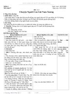
Topology – Part 1 (FTP)
Part 1 will highlight a TCP capture of an FTP session. This topology consists of a PC with Internet access.
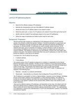
Topology – Part 2 (TFTP)
Part 2 will highlight a UDP capture of a TFTP session. The PC must have both an Ethernet connection and a
console connection to Switch S1.
Addressing Table (Part 2)
Device
Interface
IP Address
Subnet Mask
Default Gateway
S1
VLAN 1
192.168.1.1
255.255.255.0
N/A
PC-A
NIC
192.168.1.3
255.255.255.0
192.168.1.1
Objectives
Part 1: Identify TCP Header Fields and Operation Using a Wireshark FTP Session Capture
Part 2: Identify UDP Header Fields and Operation Using a Wireshark TFTP Session Capture
Background / Scenario
Two protocols in the TCP/IP transport layer are TCP (defined in RFC 761) and UDP (defined in RFC 768).
Both protocols support upper-layer protocol communication. For example, TCP is used to provide transport
layer support for the HyperText Transfer Protocol (HTTP) and FTP protocols, among others. UDP provides
transport layer support for the Domain Name System (DNS) and TFTP, among others.
Note: Understanding the parts of the TCP and UDP headers and operation are a critical skill for network
engineers.
© 2017 Cisco and/or its affiliates. All rights reserved. This document is Cisco Public.
Page 1 of 15
Lab - Using Wireshark to Examine TCP and UDP Captures
In Part 1 of this lab, you will use the Wireshark open source tool to capture and analyze TCP protocol header
fields for FTP file transfers between the host computer and an anonymous FTP server. The Windows
command line utility is used to connect to an anonymous FTP server and download a file. In Part 2 of this lab,
you will use Wireshark to capture and analyze UDP header fields for TFTP file transfers between the host
computer and S1.
Instructor Note: If Wireshark version 1.8.3 or later has not been loaded on the PC, it may be downloaded
from this URL For Part 2 of the lab, if tftpd32 version 4.0 or later has
not been installed on the PC, it may be downloaded from this URL
/>Note: The switch used is a Cisco Catalyst 2960s with Cisco IOS Release 15.0(2) (lanbasek9 image). Other
switches and Cisco IOS versions can be used. Depending on the model and Cisco IOS version, the available
commands and the output produced might vary from what displays in the labs.
Note: Make sure that the switch has been erased and has no startup configurations. If you are unsure,
contact your instructor.
Note: Part 1 assumes the PC has Internet access and cannot be performed using Netlab. Part 2 is Netlab
compatible.
Instructor Note: Instructions for erasing the switch are provided in the Lab Manual.
Instructor Note: This lab may be performed in two sessions based on time and equipment availability. The
sequence of Part 1 and Part 2 is not critical.
Instructor Note: Using a packet sniffer, such as Wireshark may be considered a breach of the security policy
of the school. It is recommended that permission be obtained before running Wireshark for this lab. If using a
packet sniffer is an issue, the instructor may wish to assign the lab as homework or perform a walk-through
demonstration.
Required Resources – Part 1 (FTP)
1 PC (Windows 7 or 8 with command prompt access, Internet access, and Wireshark installed)
Required Resources – Part 2 (TFTP)
•
1 Switch (Cisco 2960 with Cisco IOS Release 15.0(2) lanbasek9 image or comparable)
•
1 PC (Windows 7 or 8 with Wireshark and a TFTP server, such as tftpd32 installed)
•
Console cable to configure the Cisco IOS devices via the console port
•
Ethernet cable as shown in the topology
Part 1: Identify TCP Header Fields and Operation Using a Wireshark FTP
Session Capture
In Part 1, you use Wireshark to capture an FTP session and inspect TCP header fields.
Step 1: Start a Wireshark capture.
a. Close all unnecessary network traffic, such as the web browser, to limit the amount traffic during the
Wireshark capture.
b. Start the Wireshark capture.
Step 2: Download the Readme file.
a. From the command prompt, enter ftp ftp.cdc.gov.
© 2017 Cisco and/or its affiliates. All rights reserved. This document is Cisco Public.
Page 2 of 15
Lab - Using Wireshark to Examine TCP and UDP Captures
b. Log into the FTP site for Centers for Disease Control and Prevention (CDC) with user anonymous and
no password.
c.
Locate and download the Readme file by entering the ls command to list the files.
d. Enter the command get Readme to download the file. When the download is complete, enter the
command quit to exit.
Step 3: Stop the Wireshark capture.
Step 4: View the Wireshark main window.
Wireshark captured many packets during the FTP session to ftp.cdc.gov. To limit the amount of data for
analysis, type tcp and ip.addr == 198.246.117.106 in the Filter: entry area and click Apply. The IP address,
198.246.117.106, is the address for ftp.cdc.gov at this time.
© 2017 Cisco and/or its affiliates. All rights reserved. This document is Cisco Public.
Page 3 of 15
Lab - Using Wireshark to Examine TCP and UDP Captures
Step 5: Analyze the TCP fields.
After the TCP filter has been applied, the first three frames in the packet list pane (top section) display the
transport layer protocol TCP creating a reliable session. The sequence of [SYN], [SYN, ACK], and [ACK]
illustrates the three-way handshake.
TCP is routinely used during a session to control datagram delivery, verify datagram arrival, and manage
window size. For each data exchange between the FTP client and FTP server, a new TCP session is started.
At the conclusion of the data transfer, the TCP session is closed. When the FTP session is finished, TCP
performs an orderly shutdown and termination.
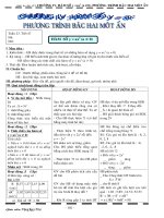
In Wireshark, detailed TCP information is available in the packet details pane (middle section). Highlight the
first TCP datagram from the host computer, and expand the TCP datagram. The expanded TCP datagram
appears similar to the packet detail pane shown below.
© 2017 Cisco and/or its affiliates. All rights reserved. This document is Cisco Public.
Page 4 of 15
Lab - Using Wireshark to Examine TCP and UDP Captures
The image above is a TCP datagram diagram. An explanation of each field is provided for reference:
•
The TCP source port number belongs to the TCP session host that opened a connection. The value is
normally a random value above 1,023.
•
The TCP destination port number is used to identify the upper layer protocol or application on the
remote site. The values in the range 0–1,023 represent the “well-known ports” and are associated with
popular services and applications (as described in RFC 1700), such as Telnet, FTP, and HTTP. The
combination of the source IP address, source port, destination IP address, and destination port uniquely
identifies the session to the sender and receiver.
Note: In the Wireshark capture below, the destination port is 21, which is FTP. FTP servers listen on port 21
for FTP client connections.
•
The Sequence number specifies the number of the last octet in a segment.
•
The Acknowledgment number specifies the next octet expected by the receiver.
•
The Code bits have a special meaning in session management and in the treatment of segments. Among
interesting values are:
© 2017 Cisco and/or its affiliates. All rights reserved. This document is Cisco Public.
Page 5 of 15
Lab - Using Wireshark to Examine TCP and UDP Captures
-
ACK — Acknowledgement of a segment receipt.
-
SYN — Synchronize, only set when a new TCP session is negotiated during the TCP three-way
handshake.
-
FIN — Finish, the request to close the TCP session.
•
The Window size is the value of the sliding window. It determines how many octets can be sent before
waiting for an acknowledgement.
•
The Urgent pointer is only used with an Urgent (URG) flag when the sender needs to send urgent data
to the receiver.
•
The Options has only one option currently, and it is defined as the maximum TCP segment size (optional
value).
Using the Wireshark capture of the first TCP session startup (SYN bit set to 1), fill in information about the
TCP header.
From the PC to CDC server (only the SYN bit is set to 1):
Source IP address
192.168.1.17*
Destination IP address
198.246.117.106
Source port number
49411*
Destination port number
21
Sequence number
0 (relative)
Acknowledgement number
Not applicable for this capture
Header length
32 bytes
Window size
8192
*Student answers will vary.
In the second Wireshark filtered capture, the CDC FTP server acknowledges the request from the PC. Note
the values of the SYN and ACK bits.
© 2017 Cisco and/or its affiliates. All rights reserved. This document is Cisco Public.
Page 6 of 15
Lab - Using Wireshark to Examine TCP and UDP Captures
Fill in the following information regarding the SYN-ACK message.
Source IP address
198.246.117.106
Destination IP address
192.168.1.17*
Source port number
21
Destination port number
49411*
Sequence number
0 (relative)
Acknowledgement number
1 (relative)
Header length
32 bytes
Window size
8192
*Student answers will vary.
In the final stage of the negotiation to establish communications, the PC sends an acknowledgement
message to the server. Notice only the ACK bit is set to 1, and the Sequence number has been incremented
to 1.
© 2017 Cisco and/or its affiliates. All rights reserved. This document is Cisco Public.
Page 7 of 15
Lab - Using Wireshark to Examine TCP and UDP Captures
Fill in the following information regarding the ACK message.
Source IP address
192.168.1.17*
Destination IP address
198.246.112.54
Source port number
49411*
Destination port number
21
Sequence number
1 (relative)
Acknowledgement number
1 (relative)
Header length
20
Window size
8192*
*Student answers will vary.
How many other TCP datagrams contained a SYN bit?
_______________________________________________________________________________________
One. The first packet sent by the host at the beginning of a TCP session.
After a TCP session is established, FTP traffic can occur between the PC and FTP server. The FTP client and
server communicate with each other, unaware that TCP has control and management over the session. When
the FTP server sends a Response: 220 to the FTP client, the TCP session on the FTP client sends an
acknowledgment to the TCP session on the server. This sequence is visible in the Wireshark capture below.
© 2017 Cisco and/or its affiliates. All rights reserved. This document is Cisco Public.
Page 8 of 15
Lab - Using Wireshark to Examine TCP and UDP Captures
When the FTP session has finished, the FTP client sends a command to “quit”. The FTP server acknowledges
the FTP termination with a Response: 221 Goodbye. At this time, the FTP server TCP session sends a TCP
datagram to the FTP client, announcing the termination of the TCP session. The FTP client TCP session
acknowledges receipt of the termination datagram, then sends its own TCP session termination. When the
originator of the TCP termination (the FTP server) receives a duplicate termination, an ACK datagram is sent
to acknowledge the termination and the TCP session is closed. This sequence is visible in the diagram and
capture below.
By applying an ftp filter, the entire sequence of the FTP traffic can be examined in Wireshark. Notice the
sequence of the events during this FTP session. The username anonymous was used to retrieve the
Readme file. After the file transfer completed, the user ended the FTP session.
© 2017 Cisco and/or its affiliates. All rights reserved. This document is Cisco Public.
Page 9 of 15
Lab - Using Wireshark to Examine TCP and UDP Captures
Apply the TCP filter again in Wireshark to examine the termination of the TCP session. Four packets are
transmitted for the termination of the TCP session. Because TCP connection is full-duplex, each direction
must terminate independently. Examine the source and destination addresses.
In this example, the FTP server has no more data to send in the stream. It sends a segment with the FIN flag
set in frame 149. The PC sends an ACK to acknowledge the receipt of the FIN to terminate the session from
the server to the client in frame 150.
In frame 151, the PC sends a FIN to the FTP server to terminate the TCP session. The FTP server responds
with an ACK to acknowledge the FIN from the PC in frame 152. Now the TCP session terminated between the
FTP server and PC.
Part 2: Identify UDP Header Fields and Operation Using a Wireshark TFTP
Session Capture
In Part 2, you use Wireshark to capture a TFTP session and inspect the UDP header fields.
Step 1: Set up this physical topology and prepare for TFTP capture.
a. Establish a console and Ethernet connection between PC-A and S1.
© 2017 Cisco and/or its affiliates. All rights reserved. This document is Cisco Public.
Page 10 of 15
Lab - Using Wireshark to Examine TCP and UDP Captures
b. Manually configure the IP address on the PC to 192.168.1.3. It is not required to set the default gateway.
c.
Configure the switch. Assign an IP address of 192.168.1.1 to VLAN 1. Verify connectivity with the PC by
pinging 192.168.1.3. Troubleshoot as necessary.
Switch> enable
Switch# conf t
Enter configuration commands, one per line. End with CNTL/Z.
Switch(config)# host S1
S1(config)# interface vlan 1
S1(config-if)# ip address 192.168.1.1 255.255.255.0
S1(config-if)# no shut
*Mar 1 00:37:50.166: %LINK-3-UPDOWN: Interface Vlan1, changed state to up
*Mar 1 00:37:50.175: %LINEPROTO-5-UPDOWN: Line protocol on Interface Vlan1,
changed state to up
S1(config-if)# end
S1# ping 192.168.1.3
Type escape sequence to abort.
Sending 5, 100-byte ICMP Echos to 192.168.1.3, timeout is 2 seconds:
!!!!!
Success rate is 100 percent (5/5), round-trip min/avg/max = 1/203/1007 ms
d. Save the running configuration to NVRAM.
S1# copy run start
Step 2: Prepare the TFTP server on the PC.
a. If it does not already exist, create a folder on the PC desktop called TFTP. The files from the switch will
be copied to this location.
b. Start tftpd32 on the PC.
c.
Click Browse and change the current directory to C:\Users\user1\Desktop\TFTP by replacing user1 with
your username.
The TFTP server should look like this:
© 2017 Cisco and/or its affiliates. All rights reserved. This document is Cisco Public.
Page 11 of 15
Lab - Using Wireshark to Examine TCP and UDP Captures
Notice that in Current Directory, it lists the user and the Server (PC-A) interface with the IP address of
192.168.1.3.
d. Test the ability to copy a file using TFTP from the switch to the PC. Troubleshoot as necessary.
S1# copy start tftp
Address or name of remote host []? 192.168.1.3
Destination filename [s1-confg]?
!!
1638 bytes copied in 0.026 secs (63000 bytes/sec)
If you see that the file has been copied then you are ready to go on to the next step. If the file has not
been copied, troubleshoot as needed. If you get the %Error opening tftp (Permission denied)
error, determine whether your firewall is blocking TFTP and whether you are copying the file to a location
where your username has adequate permission, such as the desktop.
Step 3: Capture a TFTP session in Wireshark
a. Open Wireshark. From the Edit menu, choose Preferences and click the (+) sign to expand Protocols.
Scroll down and select UDP. Click the Validate the UDP checksum if possible check box and click
Apply. Then click OK.
Instructor Note: This is a change from previous versions of this lab because the technology has
changed. Search for “checksum offloading in Wireshark”.
b. Start a Wireshark capture.
c.
Run the copy start tftp command on the switch.
d. Stop the Wireshark capture.
e. Set the filter to tftp. Your output should look similar to the output shown above. This TFTP transfer is used
to analyze transport layer UDP operations.
Instructor Note: If students point out UDP acknowledgements, explain that the UDP header does not
contain an acknowledgement field. It is the responsibility of the upper-layer protocol, in this case TFTP, to
manage data transfer and receipt information. This will be shown during the UDP datagram examination.
© 2017 Cisco and/or its affiliates. All rights reserved. This document is Cisco Public.
Page 12 of 15
Lab - Using Wireshark to Examine TCP and UDP Captures
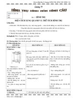
Detailed UDP information is available in the Wireshark packet details pane. Highlight the first UDP
datagram from the host computer and move the mouse pointer to the packet details pane. It may be
necessary to adjust the packet details pane and expand the UDP record by clicking the protocol expand
box. The expanded UDP datagram should look similar to the diagram below.
The figure below is a UDP datagram diagram. Header information is sparse, compared to the TCP
datagram. Similar to TCP, each UDP datagram is identified by the UDP source port and UDP destination
port.
Using the Wireshark capture of the first UDP datagram, fill in information about the UDP header. The
checksum value is a hexadecimal (base 16) value, denoted by the preceding 0x code:
Source IP address
192.168.1.1
Destination IP address
192.168.1.3
Source port number
62513*
Destination port number
69
UDP message length
25 bytes*
UDP checksum
0x482c [correct]*
*Student answers will vary.
How does UDP verify datagram integrity?
____________________________________________________________________________________
____________________________________________________________________________________
A checksum is sent in the UDP datagram, and the datagram checksum value is recomputed upon receipt.
If the computed checksum is identical to the sent checksum, then the UDP datagram is assumed to be
complete.
Examine the first frame returned from the tftpd server. Fill in the information about the UDP header:
© 2017 Cisco and/or its affiliates. All rights reserved. This document is Cisco Public.
Page 13 of 15
Lab - Using Wireshark to Examine TCP and UDP Captures
Source IP address
192.168.1.3
Destination IP address
192.168.1.1
Source port number
58565*
Destination port number
62513*
UDP message length
12 bytes*
UDP checksum
Checksum: 0x8372 [incorrect, should be
0xa385 (maybe caused by "UDP checksum
offload"?)]*
*Student answers will vary.
Notice that the return UDP datagram has a different UDP source port, but this source port is used for the
remainder of the TFTP transfer. Because there is no reliable connection, only the original source port
used to begin the TFTP session is used to maintain the TFTP transfer.
Also, notice that the UDP Checksum is incorrect. This is most likely caused by UDP checksum offload.
You can learn more about why this happens by searching for “UDP checksum offload”.
Reflection
This lab provided the opportunity to analyze TCP and UDP protocol operations from captured FTP and TFTP
sessions. How does TCP manage communication differently than UDP?
_______________________________________________________________________________________
_______________________________________________________________________________________
TCP manages communication much differently than UDP because reliability and guaranteed delivery requires
additional control over the communication channel. UDP has less overhead and control, and the upper-layer
protocol must provide some type of acknowledgement control. Both protocols, however, transport data
between clients and servers using Application Layer protocols and are appropriate for the upper-layer protocol
each supports.
Challenge
Because neither FTP or TFTP are secure protocols, all transferred data is sent in clear text. This includes any
user IDs, passwords, or clear-text file contents. Analyzing the upper-layer FTP session will quickly identify the
user ID, password, and configuration file passwords. Upper-layer TFTP data examination is more
complicated, but the data field can be examined, and the configuration’s user ID and password information
extracted.
Cleanup
Unless directed otherwise by your instructor:
1) Remove the files that were copied to your PC.
© 2017 Cisco and/or its affiliates. All rights reserved. This document is Cisco Public.
Page 14 of 15
Lab - Using Wireshark to Examine TCP and UDP Captures
2) Erase the configurations on S1.
3) Remove the manual IP address from the PC and restore Internet connectivity.
Device Configs
Switch S1
S1#show run
Building configuration...
!
hostname S1
!
interface Vlan1
ip address 192.168.1.1 255.255.255.0
!
end
© 2017 Cisco and/or its affiliates. All rights reserved. This document is Cisco Public.
Page 15 of 15