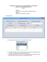
Thông Báo - Võ Tấn Dũng (votandung) Click ThucHanhCCNA1_buoi1
Bạn đang xem bản rút gọn của tài liệu. Xem và tải ngay bản đầy đủ của tài liệu tại đây (700.84 KB, 8 trang )
L
Lab - Co
onfigurin
ng a Switch Man
nageme
ent Addrress
T
Topology
A
Addressing
g Table
Device
D
Interface
IP Address
A
Subnet Mas
sk
Defau
ult Gateway
S1
VLAN 1
192.16
68.1.2
2
255.255.255.0
0
N/A
PC
C-A
NIC
192.16
68.1.10
2
255.255.255.0
0
N/A
O
Objectives
Part 1: Co
onfigure a Basic Network
k Device
Cable
e the network as shown in the topology.
Config
gure basic sw
witch settings including hos
stname, mana
agement address, and Telnet access.
Config
gure an IP ad
ddress on the PC.
Part 2: Ve
erify and Tes
st Network Connectivity
C
Displa
ay device con
nfiguration.
Test end-to-end
e
co
onnectivity witth ping.
Test remote
r
manag
gement capability with Telnet.
Save the switch running configu
uration file.
B
Backgroun
nd / Scenarrio
Cisco switches have a special interfface, known as
a a switch vi rtual interface
e (SVI). The S
SVI can be co
onfigured
with an IP
P address, com
mmonly referrred to as the managementt address tha
at is used for rremote accesss to the
switch to display
d
or con
nfigure setting
gs.
In this lab
b, you will build a simple ne
etwork using Ethernet
E
LAN
N cabling and access a Cissco switch using the
console and
a remote ac
ccess method
ds. You will co
onfigure basicc switch settin
ngs and IP ad
ddressing, and
d
demonstra
ate the use of a managem
ment IP addres
ss for remote switch mana
agement. The topology con
nsists of
one switch and one ho
ost using only Ethernet and
d console portts.
Note: The
e switches used are Cisco Catalyst 2960s with Cisco
o IOS Release
e 15.0(2) (lan
nbasek9 imag
ge). Other
switches and
a Cisco IOS
S versions ca
an be used. Depending
D
on the model an
nd Cisco IOS version, the available
command
ds and output produced might vary from
m what is show
wn in the labss.
Note: Make sure that the switch has
s been erased
d and has no startup configuration. If yo
ou are unsure
e, contact
your instru
uctor.
R
Required Resources
R
1 Switch (Cisco 29
960 with Cisco
o IOS Release 15.0(2) lanb
basek9 image
e or compara
able)
© 2013 Cisco and
d/or its affiliates. All rights reserve
ed. This docume
ent is Cisco Publiic.
Page 1 of 8
Lab - Configuring a Switch Management Address
1 PC (Windows 7, Vista, or XP with terminal emulation program, such as Tera Term)
Console cables to configure the Cisco IOS devices via the console ports
Ethernet cables as shown in the topology
Part 1: Configure a Basic Network Device
In Part 1, you will set up the network and configure basic settings, such as hostnames, interface IP
addresses, and passwords.
Step 1: Cable the network.
a. Cable the network as shown in the topology.
b. Establish a console connection to the switch from PC-A.
Step 2: Configure basic switch settings.
In this step, you will configure basic switch settings, such as hostname and configuring an IP address for the
SVI. Assigning an IP address on the switch is only the first step. As the network administrator, you must
specify how the switch will be managed. Telnet and Secure Shell (SSH) are two of the most common
management methods; however, Telnet is a very insecure protocol. All information flowing between the two
devices is sent in plain text. Passwords and other sensitive information can be easily looked at if captured by
a packet sniffer.
a. Assuming the switch had no configuration file stored in nonvolatile random-access memory (NVRAM),
you will be at the user EXEC mode prompt on the switch with a prompt of Switch>. Enter privileged
EXEC mode.
Switch> enable
Switch#
b. Verify a clean configuration file with the show running-config privileged EXEC command. If a
configuration file was previously saved, it will have to be removed. Depending on the switch model and
IOS version, your configuration may look slightly different. However, there should be no configured
passwords or IP address set. If your switch does not have a default configuration, ask your instructor for
help.
c.
Enter global configuration mode and assign the switch hostname.
Switch# configure terminal
Switch(config)# hostname S1
S1(config)#
d. Configure the switch password access.
S1(config)# enable secret class
S1(config)#
e. Prevent unwanted Domain Name System (DNS) lookups.
S1(config)# no ip domain-lookup
S1(config)#
f.
Configure a login message-of-the-day (MOTD) banner.
S1(config)# banner motd #
Enter Text message. End with the character ‘#’.
Unauthorized access is strictly prohibited. #
© 2013 Cisco and/or its affiliates. All rights reserved. This document is Cisco Public.
Page 2 of 8
Lab - Configuring a Switch Management Address
g. Verify your access setting by moving between modes.
S1(config)# exit
S1#
S1# exit
Unauthorized access is strictly prohibited.
S1>
What shortcut keys are used to go directly from global configuration mode to privileged EXEC mode?
h. Return to privileged EXEC mode from user EXEC mode.
S1> enable
Password: class
S1#
Note: Password will not show up on screen when entering.
i.
Enter global configuration mode to set the SVI IP address to allow remote switch management.
S1# config t
S1#(config)# interface vlan 1
S1(config-if)# ip address 192.168.1.2 255.255.255.0
S1(config-if)# no shut
S1(config-if)# exit
S1(config)#
j.
Restrict console port access. The default configuration is to allow all console connections with no
password needed.
S1(config)# line
S1(config-line)#
S1(config-line)#
S1(config-line)#
S1(config)#
k.
con 0
password cisco
login
exit
Configure the virtual terminal (VTY) line for the switch to allow Telnet access. If you do not configure a
VTY password, you will not be able to Telnet to the switch.
S1(config)# line vty 0 4
S1(config-line)# password cisco
S1(config-line)# login
S1(config-line)# end
S1#
*Mar 1 00:06:11.590: %SYS-5-CONFIG_I: Configured from console by console
© 2013 Cisco and/or its affiliates. All rights reserved. This document is Cisco Public.
Page 3 of 8
Lab - Configuring a Switch Management Address
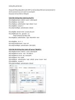
Step 3: Configure an IP address on PC-A.
a. Assign the IP address and subnet mask to the PC, as shown in the Addressing Table on page 1. The
procedure for assigning an IP address on a PC running Windows 7 is described below:
1) Click the Windows Start icon > Control Panel.
2) Click View By: > Category.
3) Choose View network status and tasks > Change adapter settings.
4) Right-click Local Area Network Connection and select Properties.
5) Choose Internet Protocol Version 4 (TCP/IPv4), click Properties > OK.
6) Click the Use the following IP address radio button and enter the IP address and subnet mask.
Part 2: Verify and Test Network Connectivity
You will now verify and document the switch configuration, test end-to-end connectivity between PC-A and
S1, and test the remote management capability of the switch.
Step 1: Display the S1 device configuration.
a. Return to your console connection using Tera Term on PC-A to display and verify your switch
configuration by issuing the show run command. A sample configuration is shown below. The settings
you configured are highlighted in yellow. The other configuration settings are IOS defaults.
S1# show run
Building configuration...
Current configuration : 1508 bytes
!
! Last configuration change at 00:06:11 UTC Mon Mar 1 1993
!
version 15.0
no service pad
service timestamps debug datetime msec
service timestamps log datetime msec
no service password-encryption
!
hostname S1
!
boot-start-marker
boot-end-marker
!
enable secret 4 06YFDUHH61wAE/kLkDq9BGho1QM5EnRtoyr8cHAUg.2
!
no aaa new-model
system mtu routing 1500
!
!
no ip domain-lookup
!
spanning-tree mode pvst
© 2013 Cisco and/or its affiliates. All rights reserved. This document is Cisco Public.
Page 4 of 8
Lab - Configuring a Switch Management Address
spanning-tree extend system-id
!
vlan internal allocation policy ascending
!
!
interface FastEthernet0/1
!
interface FastEthernet0/2
<output omitted>
interface FastEthernet0/24
!
interface GigabitEthernet0/1
!
interface GigabitEthernet0/2
!
interface Vlan1
ip address 192.168.1.2 255.255.255.0
!
ip http server
ip http secure-server
!
banner motd ^C
Unauthorized access is strictly prohibited. ^C
!
line con 0
password cisco
login
line vty 0 4
password cisco
login
line vty 5 15
login
!
end
b. Verify the status of your SVI management interface. Your VLAN 1 interface should be up/up and have an
IP address assigned. Notice that switch port F0/6 is also up because PC-A is connected to it. Because all
switch ports are initially in VLAN 1, by default, you can communicate with the switch using the IP address
you configured for VLAN 1.
S1# show ip interface brief
Interface
Vlan1
FastEthernet0/1
FastEthernet0/2
FastEthernet0/3
FastEthernet0/4
FastEthernet0/5
FastEthernet0/6
IP-Address
192.168.1.2
unassigned
unassigned
unassigned
unassigned
unassigned
unassigned
OK?
YES
YES
YES
YES
YES
YES
YES
Method
manual
unset
unset
unset
unset
unset
unset
© 2013 Cisco and/or its affiliates. All rights reserved. This document is Cisco Public.
Status
up
down
down
down
down
down
up
Protocol
up
down
down
down
down
down
up
Page 5 of 8
L
Lab - Configu
uring a Switc
ch Managem
ment Address
s
FastE
Ethernet0/7
FastE
Ethernet0/8
FastE
Ethernet0/9
FastE
Ethernet0/10
0
FastE
Ethernet0/11
1
FastE
Ethernet0/12
2
FastE
Ethernet0/13
3
FastE
Ethernet0/14
4
FastE
Ethernet0/15
5
FastE
Ethernet0/16
6
FastE
Ethernet0/17
7
FastE
Ethernet0/18
8
FastE
Ethernet0/19
9
FastE
Ethernet0/20
0
FastE
Ethernet0/21
1
FastE
Ethernet0/22
2
FastE
Ethernet0/23
3
FastE
Ethernet0/24
4
Gigab
bitEthernet0
0/1
Gigab
bitEthernet0
0/2
una
assigned
una
assigned
una
assigned
una
assigned
una
assigned
una
assigned
una
assigned
una
assigned
una
assigned
una
assigned
una
assigned
una
assigned
una
assigned
una
assigned
una
assigned
una
assigned
una
assigned
una
assigned
una
assigned
una
assigned
YES
YES
YES
YES
YES
YES
YES
YES
YES
YES
YES
YES
YES
YES
YES
YES
YES
YES
YES
YES
unse
et
et
unse
et
unse
et
unse
et
unse
et
unse
et
unse
unse
et
et
unse
et
unse
et
unse
et
unse
et
unse
et
unse
et
unse
et
unse
et
unse
et
unse
et
unse
et
unse
down
down
down
down
down
down
down
down
down
down
down
down
down
down
down
down
down
down
down
down
down
down
down
down
down
down
down
down
down
down
down
down
down
down
down
down
down
down
down
down
S
Step 2: Tes
st end-to-en
nd connectiv
vity.
Open a co
ommand prom
mpt window (c
cmd.exe) on PC-A by clickking the Wind
dows Start iccon and enter cmd into
the Searc
ch for progra
ams and files
s field. Verify the
t IP addresss of PC-A byy using the ipc
config /all co
ommand.
This comm
mand displays the PC hostname and th
he IPv4 addre
ess informatio
on. Ping PC-A
A’s own addre
ess and
the manag
gement addre
ess of S1.
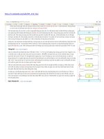
a. Ping your
y
own PC--A address firrst.
C:\Us
sers\NetAc
cad> ping 192.168.1.
1
10
Your output should
d be similar to
o the following
g screen:
© 2013 Cisco and
d/or its affiliates. All rights reserve
ed. This docume
ent is Cisco Publiic.
Page 6 of 8
L
Lab - Configu
uring a Switc
ch Managem
ment Address
s
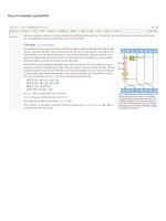
b. Ping the
t SVI mana
agement addrress of S1.
C:\Us
sers\NetAc
cad> ping 192.168.1.
1
2
Your output should
d be similar to
o the following
g screen. If pi ng results are
e not successsful, troublesh
hoot the
basic device config
gurations. You
u should chec
ck both the ph
hysical cablin
ng and IP add
dressing, if ne
ecessary.
S
Step 3: Tes
st and verify
y remote ma
anagement of S1.
You will now use Telne
et to remotely
y access the switch
s
S1 usin
ng the SVI ma
anagement address. In this lab,
PC-A and
d S1 reside sid
de by side. In
n a production
n network, the
e switch could
d be in a wirin
ng closet on th
he top
floor while
e your manag
gement PC is located on th
he ground floo
or. Telnet is n
not a secure p
protocol. However, you
will use it in this lab to test remote access.
a
All info
ormation sen t by Telnet, in
ncluding passswords and
command
ds, is sent acrross the sessiion in plain te
ext. In subseq uent labs, yo u will use Seccure Shell (SS
SH) to
remotely access
a
netwo
ork devices.
Note: Win
ndows 7 does
s not natively support Telne
et. The admin
nistrator mustt enable this p
protocol. To in
nstall the
Telnet clie
ent, open a co
ommand prom
mpt window and
a type pkgm
mgr /iu:“T
TelnetClien
nt”.
C:\Us
sers\NetAc
cad> pkgmgr
r /iu:”Tel
lnetClient”
”
a. With the
t command
d prompt wind
dow still open on PC-A, isssue a Telnet ccommand to cconnect to S1 via the
SVI management
m
address.
a
The password is cisco.
C:\Us
sers\NetAc
cad> telnet
t 192.168.1.2
Your output should
d be similar to
o the following
g screen:
© 2013 Cisco and
d/or its affiliates. All rights reserve
ed. This docume
ent is Cisco Publiic.
Page 7 of 8
L
Lab - Configu
uring a Switc
ch Managem
ment Address
s
b. After entering the cisco
c
passwo
ord, you will be
b at the userr EXEC mode
e prompt. Type enable at th
he
promp
pt. Enter the class
c
passwo
ord to enter privileged EXE
EC mode and issue a show
w run comma
and.
S
Step 4: Sav
ve the configuration file.
a. From your Telnet session,
s
issue
e the copy ru
un start comm
mand at the p
prompt.
c
run start
s
S1# copy
Desti
ination fi
ilename [st
tartup-con
nfig]? [Ent
ter]
Build
ding confi
iguration ..
.
S1#
d to the Wind
he Telnet ses
ssion by typing
g quit. You will
w be returned
dows 7 comm
mand prompt.
b. Exit th
R
Reflection
Why mustt you use a co
onsole conne
ection to initiallly configure tthe switch? W
Why not conne
ect to the swittch via
Telnet or SSH?
© 2013 Cisco and
d/or its affiliates. All rights reserve
ed. This docume
ent is Cisco Publiic.
Page 8 of 8