DSpace at VNU: An influence of bottom electrode material on electrical conduction and resistance switching of TiOx thin films
Bạn đang xem bản rút gọn của tài liệu. Xem và tải ngay bản đầy đủ của tài liệu tại đây (1.29 MB, 6 trang )
Eur. Phys. J. Appl. Phys. (2013) 64: 30102
DOI: 10.1051/epjap/2013130255
THE EUROPEAN
PHYSICAL JOURNAL
APPLIED PHYSICS
Regular Article
An influence of bottom electrode material on electrical
conduction and resistance switching of TiOx thin films
Kim Ngoc Pham1 , Trung Do Nguyen1 , Thi Kieu Hanh Ta1 , Khanh Linh Dao Thuy1 , Van Hieu Le1 ,
Duy Phong Pham2 , Cao Vinh Tran2 , Derrick Mott3 , Shinya Maenosono3 , Sang Sub Kim4 , Jaichan Lee5 ,
Duc Thang Pham6 , and Bach Thang Phan1,2,a
1
2
3
4
5
6
Faculty of Materials Science, University of Science, Vietnam National University, Ho Chi Minh, Vietnam
Laboratory of Advanced Materials, University of Science, Vietnam National University, Ho Chi Minh, Vietnam
Japan Advanced Institute of Science and Technology, 1-1 Asahidai, Nomi, Ishikawa, Japan
School of Materials Science and Engineering, Inha University, Incheon 402-751, South Korea
School of Advanced Materials Science and Engineering, Sungkyunkwan University, Suwon 440-746, South Korea
Faculty of Engineering Physics and Nanotechnology, University of Engineering and Technology, Vietnam National University,
Hanoi, Vietnam
Received: 27 May 2013 / Received in final form: 23 September 2013 / Accepted: 7 November 2013
Published online: 9 December 2013 – c EDP Sciences 2013
Abstract. We investigated the electrical conduction and resistance switching mechanisms of TiOx thin
films grown on three kinds of bottom electrode at room temperature (an inert Pt, an active Ti and
fluorine tin oxide FTO electrodes). The bottom electrode materials strongly affect the I-V characteristics
and switching parameters. The I-V characteristic is explained through the presence of interface states in
the metal electrode devices (Pt and Ti) and the work function in the metal oxide device (FTO). The Pt
device has the smallest VSET and largest switching ratio, while the Ti device shows the largest VSET and
smallest switching ratio. XPS data shows non-lattice oxygen in TiOx films. Therefore, the proposed bipolar
resistance switching arises from formation and rupture of filament paths, generated by the movement of
oxygen vacancies. All devices depict the same electrical conductions, trap-controlled space-charge-limited,
FN tunneling and Ohmic conductions for a high resistance state and a low resistance state, respectively.
In this study, the rarely reported FN tunneling conduction in published TiOx -based ReRAM device was
found, which can be attributed to an influence of the bottom electrode on the electronic distribution in
devices.
1 Introduction
Resistive switching in TiO2 thin films has attracted significant attention for possible application in nonvolatile
memory devices. Some works reported the role of electrode
on the resistance switching of TiO2 thin films. Park et al.,
reported the bipolar resistance switching of Ir/TiOx /TiN
structure due to a variation of oxygen vacancy concentration at top Ir/TiOx interface [1]. Choi et al., found that the
resistance switching of TiO2 films significantly depended
on a bias polarity to the top electrode (Al, Pt) [2]. Jung et
al., presented the switching in the Al/a-TiOx /ITO structure, which results from the migration of the oxygen vacancies in the a-TiOx [3]. Yang et al., compared the role
of different top metal electrode on the resistance switching of a-TiO2 films in the top electrode (Pt, Au, Ag, Ni,
W and Ti)/a-TiO2 /Pt structure. The resistance switching is controlled by the chemical reaction between the top
electrode materials and TiO2 layer [4].
a
e-mail:
However, there is a lack in work regarding the role of
the bottom electrode. In this study, we aim to compare the
role of three kinds of electrode: an inert Pt electrode, an
active Ti electrode and a fluorine tin oxide FTO electrode
on electrical conduction and resistance switching behavior
of Ag/TiOx /bottom electrode device.
2 Experiments
In this study, fluorine tin oxide/glass (FTO) and
Pt/TiO2 /SiO2 /Si substrate are commercial samples. The
other electrodes (Ti and Ag) and TiOx thin films were
fabricated from metallic (Ti, Ag) targets by using the dc
sputtering technique at room temperature. 100-nm-thick
metallic Ti and Ag layers were deposited as bottom and
top electrodes at a pressure of 2 mTorr in an Ar environment. The 100-nm-thick TiOx thin film was prepared in a
mixture of Ar + O2 (6%) gases at a pressure of 7 mTorr.
During the deposition of the top Ag layer, a mask was used
30102-p1
The European Physical Journal Applied Physics
(a)
(b)
Fig. 1. XRD pattern of TiO2 /glass substrate.
(c)
for top electrode patterning. The crystalline phases and
microstructures of the thin films were characterized in the
θ −2 θ mode by using a D8 advance (Bruker) X-ray diffractometer (XRD) with CuKα radiation (λ = 1.54 ˚
A). The
chemical state of TiOx composition was determined by
X-ray photoelectron spectroscopy (XPS). Current-voltage
(I-V) measurements were carried out using a Semiconductor characterization system (Keithley 4200 SCS) and
probe station.
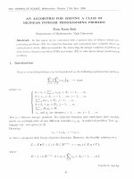
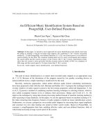
Fig. 2. XPS spectra of the O 1s of (a) FTO, (b) Pt and (c)
Ti devices.
3 Results and discussions
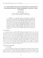
Figure 1 shows the XRD pattern of the TiOx /glass substrate. There are not any crystalline peaks in the XRD
pattern. Since the TiOx thin films were deposited on glass,
FTO, Ti and Pt/TiO2 /SiO2 /Si substrates at room temperature, we believe that the grown TiOx thin films exist
in an amorphous phase. This result is consistent to the
published literatures [5,6]. Huang et al., stated that the
TiO2 thin films deposited on the Pt bottom electrode at
room temperature result in amorphous phase [5]. In addition, the TiO2 thin films grown on Pt/Ti/SiO2 /Si substrate is reported to be amorphous phase in spite of the
post-annealing treatment at 250 ◦ C for 1 h [6]. Figure 2
shows XPS spectra of TiOx films deposited on various
electrodes. The core level spectra of O 1s can be deconvoluted into two peaks corresponding to lattice oxygen (LO,
∼530 eV) O-Ti and non-lattice oxygen (NLO, ∼531.7 eV).
The presence of non-lattice oxygen ions might play an important role in the electrical conduction and resistance
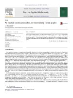
switching mechanism. Figure 3 shows that the XPS spectra consist of Ti4+ (Ti 2p3/2 ∼ 458.4 eV – 458.8 eV and
Ti 2p1/2 ∼ 463.3 eV – 464.3 eV). This indicates that Ti4+
ions are dominant in those devices. However, both the
peaks at the lower binding energy, 529 eV and 457.4 eV,
are observed in the XPS spectra of the TiOx /Pt devices,
as shown in Figures 2b and 3b. Both peaks might correspond to the occurrence of Ti2 O3 phase [7,8].
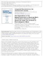
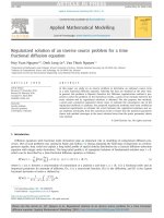
Figure 4 shows the I-V characteristics of devices with
various bottom electrodes (FTO, Pt and Ti). All the I-V
curves show the bipolar switching characteristic. For all
devices, the as-prepared state is a high resistance state
(HRS). The HRS is changed to a low resistance state
(LRS) in the negatively biased process (0 to −2 V) to
the bottom electrode, whereas HRS is not changed by a
positive bias. The LRS is progressively changed to the
HRS only by a voltage sweep in the positive voltage region (0 to + Vmax , + 1.65 V for Ti and +2.5 V for the
other bottom electrodes). The I-V characteristics do not
change even after repeated stress cycles.
It should be noted that I-V characteristic (the inset
of Fig. 4) of the Ti and Pt devices cannot be explained
uniquely through the difference in work function. Among
those devices, the I-V curve of the Ti device shows the
asymmetric characteristic, even though there is a small
difference in work function between Ti (4.33 eV) and Ag
(4.26 eV) [4]. In theory, the small difference between work
function of Ti and Ag cannot induce a significant asymmetry. Therefore, this observed behavior might originate
from the high reactivity of Ti with oxygen during TiOx
film deposition, which will be discussed in the remainder
30102-p2
K.N. Pham et al.: The electrical conduction and resistance switching mechanisms of TiOx thin films
(a)
(b)
(c)
Fig. 4. Semilogarithmic I-V character of (a) FTO, (b) Pt and
(c) Ti devices. The inset is the linear plot I-V curve.
Fig. 3. XPS spectra of the Ti 2p of (a) FTO, (b) Pt and (c)
Ti devices.
of the paper. In case of the Pt device, the symmetric
I-V curves of Pt device is obtained although the top Ag
electrode and the bottom Pt electrode have a large difference in work function, Ag (4.26 eV) and Pt (5.65 eV) [4].
Since Pt is an inert electrode, which leads to high accumulation of oxygen vacancies at the Pt/TiOx interface
during the TiOx deposition, lowering the barrier height
or decreasing the difference between two interfaces [4]. As
a result, the I-V curve of Pt devices is symmetric. It is
reported that a polarization discontinuity can induce the
formation of oxygen defects and interstitials at oxide interface [9]. Therefore, the further study on the TiOx /FTO
interface is under investigation. In this report, we suggest
that the symmetry of the I-V curve of the FTO device
might be the consequence of a small difference in the work
function between the top Ag (4.26 eV) and bottom FTO
(4.5 eVe) electrodes [10]. The differences in the I-V curves
of those devices obviously stem from the bottom electrode
materials.
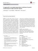
Figure 5 shows the switching voltages with the various bottom electrodes. The switching voltages (VSET and
VRESET ) vary with sweep cycles. The values of the switching voltages are listed in Table 1. In comparison, the two
metal electrode devices show an opposite switching voltages. The inert Pt electrode has the smallest VSET and the
larger VRESET , while the active Ti electrode induces the
(a)
(b)
(c)
Fig. 5. Switching voltage of (a) FTO, (b) Pt and (c) Ti devices.
30102-p3
The European Physical Journal Applied Physics
Table 1. The switching voltages of FTO, Pt and Ti devices.
FTO
Pt
Ti
VSET (V)
−0.6 V
−0.25 V
−0.75 V
VRESET (V)
+2 V
+1.8 V∼+2 V
+1.2 V∼+1.5 V
(a)
(a)
(b)
(c)
(b)
Fig. 6. Switching ratio of (a) FTO, (b) Pt and (c) Ti devices.
(c)
largest VSET and the smallest VRESET . The value of VSET
of both the Pt and Ti devices supports the above arguments of interface states induced at the bottom interface.
Among those devices, the oxide FTO electrode has an intermediate VSET and the largest VRESET . Figure 6 depicts
the switching ratio of those devices. The Pt device shows
the largest switching ratio, while the Ti device has the
smallest switching ratio.
In order to understand the role of the bottom electrode
on conduction behavior in the devices, we examined the
transport characteristics for each device. Figures 7 and 8
depict the I-V behaviors in the log-log scale. All the I-V
curves of the LRS in both the positive and the negative
biases follow the linear I-V dependence with a slope of one,
which is a typical characteristic of Ohm’s law.
The leakage current of the HRS of the devices follows
a non-linear I-V dependence where one or more of the conduction processes may be involved. Because of this, all the
I-V curves of the HRS were examinated in terms of some
potential leakage mechanisms such as space-charge-limited
conduction (SCLC), interface-limited Schottky emission
conduction (SC), interface-limited Fowler-Norheim tunneling (FN) and bulk-limited Poole-Frenkel emission
(PF) [11–15].
There is an abrupt change of current with voltage of
the HRS in the negative voltage bias as shown in
Figure 7. The leakage currents linearly depend on voltage below the VSET (I ∼ V ), and then increase steeply
on voltage (I ∼ V s , s > 2 with s ∼ 5, 7.5, 8 for FTO, Pt
and Ti, respectively). The leakage conduction is consistent
with the trap-controlled space-charge-limited conduction.
The change from the SCLC of the HRS to the Ohmic conduction of the LRS could be ascribed to the occurrence of
metallic filaments as noted in the remainder of the paper.
Fig. 7. Log-log plot of the I-V of (a) FTO, (b) Pt and (c) Ti
devices in the negative bias.
In contrast to an abrupt change of current with voltage
of the HRS in the negative biases, the current of the HRS
in the positive bias, as shown in Figure 8, which is controlled by the Ag/TiOx interface, does not suddenly vary
with voltage. Those I-V curves fit well to FN tunneling
conduction with a negative slope, as shown in
Figure 9. The inset in Figure 9 shows that the slope m of
the fitting line of the devices follows the sequence mPt >
mFTO > mTi . It is well known that FN tunneling conduction is dominant in thin dielectric films at high electric field, where the charge carriers are injected from the
electrode to the insulator by tunneling through a high potential barrier [15]. It is also noticed that the FN tunneling conduction is rarely reported in the published TiOx based ReRAM device. However, in this study we found
the FN tunneling conduction in the three investigated devices. Since the Ag and TiOx layers of those devices were
deposited on the bottom electrodes with the same depositing conditions, the different slope m can be attributed to
the different electronic distribution in the devices due to
the different bottom electrode materials.
It is noted that the SCLC conduction implied the trapping levels within the band gap and the linear I-V dependence of the LRS in both negative and positive biases gives
clues to the physical origin of the resistive switching with
the filament model [16]. A combination of these two above
observations rules out the trapping/detraping process controlled resistance switching. Therefore, it is reasonable to
30102-p4
K.N. Pham et al.: The electrical conduction and resistance switching mechanisms of TiOx thin films
creases, the injected carriers begin to fill the trap sites
and the conduction follows the SCLC. Once the electric
field through the TiOx film reaches a value at which the
filament path of oxygen vacancies connect both electrodes
throughout the TiOx film and the HRS to LRS transition
occurs. Then, large current flow along the filament path
and the conduction in the LRS follows the Ohmic behavior. In contrast, the migration of these oxygen vacancies
far away the bottom electrode caused by the reverse bias
could induce the rupture of the filament path, resulting in
the LRS to the HRS transition.
The presence of Ti2 O3 phase as a semiconductor or a
semimetal [17] embedded in the TiOx film of the Pt device in addition to high oxygen vacancy concentration at
the TiOx /Pt interface result in a low interface resistance,
leading to the easy filamentary formation or the smallest
VSET . With the Ti electrode, Ti is easily oxidized in the
presence of oxygen and forms a stable oxide layer TiOy between Ti and bulk TiOx films during the TiOx deposition.
It is also probable that Ti3+ ion in the TiOy layer acts as
a trap and captures an electron, resulting in a high interface resistance or the largely asymmetric I-V curve. This
might result in the largest VSET value of the Ti device.
For the case of the FTO bottom electrode, the absence
of reduction of TiOx thin film seems to be attributed to
the abundant oxygen at the TiOx /FTO interfaces. It may
lead to the intermediate value for VSET .
(a)
(b)
(c)
Fig. 8. Log-log plot of the I-V of (a) FTO, (b) Pt and (c) Ti
devices in the positive bias.
Fig. 9. Conventional FN tunneling plot ln (J/E2 ) vs (1/E) for
the HRS of (a) FTO, (b) Pt and (c) Ti devices in the positive
bias.
suggest that the mechanism of the formation and rupture
of filament paths consisting of oxygen vacancies controls
the observed bipolar switching behavior in the TiOx thin
films. When a negative voltage is applied to the bottom
electrodes (Pt, FTO, Ti), existing oxygen vacancies are
driven to the bottom electrode. As a negative voltage in-
4 Conclusions
In conclusion, the TiOx thin films grown on different bottom electrodes at room temperature are in an amorphous
phase with the presence of non-lattice oxygen concentration and dominant Ti4+ ions. Especially, the Ti2 O3 phase
nucleated only in the TiOx films of the inert Pt device. The
I-V characteristic of Ti and Pt devices can be explained
based on the interface states induced at the bottom interface rather than the work function. The interface states
were originated from the reactivity of the electrode with
oxygen during the TiOx film growth and significantly affected the switching voltages. The inert Pt device shows
the smallest VSET and the largest switching ratio, while
the active Ti device has the largest VSET and the smallest
switching voltage. Since the FTO electrode does not react
with the TiOx film, the FTO device gives an intermediate value of the switching parameter among the devices.
The resistance switching is controlled by formation and
rupture of filament paths consisting of the oxygen vacancies due to the migration of the oxygen vacancies under
the polarity bias. The responsible electrical conduction of
the devices is governed by the FN tunneling conduction
for the HRS in the positive bias, trap-controlled SCLC
conduction for the HRS in the negative bias, and Ohmic
conductions for the LRS in both the positive and negative
biases.
This work is funded by National Foundation of Science and
Technology Development of Vietnam (NAFOSTED – 103.992010.12).
30102-p5
The European Physical Journal Applied Physics
References
1. J.B. Park, K.P. Biju, S.J. Jung, W.T. Lee, J.M. Lee, S.H.
Kim, S.S. Park, J.H. Shin, H.S. Hwang, IEEE Electron
Device Lett. 32, 476 (2011)
2. B.J. Choi, D.S. Jeong, S.K. Kim, C. Rohde, S. Choi,
J.H. Oh, H.J. Kim, C.S. Hwang, K. Szot, R. Waser, B.
Reichenberg, S. Tiedke, J. Appl. Phys. 98, 033715 (2005)
3. S.J. Jung, J.M. Kong, S.H. Song, K.H. Lee, T.H. Lee, H.S.
Hwang, S.H. Jeon, J. Electrochem. Soc. 157, H1042 (2010)
4. J.J. Yang, J.P. Strachan, F. Miao, M.X. Zhang, M.D.
Pickett, W. Yi, D.A.A. Ohlberg, G.M. Ribeiro, R.S.
Williams, Appl. Phys. A 102, 785 (2011)
5. K.P. Biju, X.J. Liu, E.M. Bourim, I.S. Kim, S.J. Jung,
J.B. Park, H.S. Hwang, Electrochem. Solid-State Lett. 13,
H443 (2010)
6. J.J. Huang, C.W. Kuo, W.C. Chang, T.H. Hou, Appl.
Phys. Lett. 96, 262901 (2010)
7. D. Guerin, S. Ismat Shah, J. Vac. Sci. Technol. A15, 712
(1997)
8. E. McCafferty, J.P. Wightman, Appl. Surf. Sci. 143, 92
(1999)
9. J. Mannhart, D.H.A. Blank, H.Y. Hwang, A.J. Millis,
J.-M. Triscone, MRS Bulletin 33, 1027 (2008)
10. A. Andersson, N. Johansson, P. Br¨
oms, N. Yu, D. Lupo,
W.R. Salaneck, Adv. Mater. 10, 859 (1998)
11. W.Y. Yang, S.W. Rhee, Appl. Phys. Lett. 91, 232907
(2007)
12. W. Schottky, Naturw. 26, 843 (1938)
13. N.F. Mott, R.W. Gurney, Electronic Processes in Ionic
Crystals (Clarendon, Oxford, 1940)
14. J. Frenkel, Tech. Phys. USSR 5, 685 (1938)
15. S.M. Sze, Physics of Semiconductor Devices, 2nd edn.,
vol. 1 (Wiley, New York, 1981), p. 28
16. R. Waser, M. Aono, Nat. Mater. 6, 833 (2007)
17. J.M. Honig, T.B. Reed, Phys. Rev. 174, 1020 (1968)
30102-p6