DSpace at VNU: Bipolar corona discharge based air flow generation with low net charge
Bạn đang xem bản rút gọn của tài liệu. Xem và tải ngay bản đầy đủ của tài liệu tại đây (2.32 MB, 10 trang )
Sensors and Actuators A 244 (2016) 146–155
Contents lists available at ScienceDirect
Sensors and Actuators A: Physical
journal homepage: www.elsevier.com/locate/sna
Bipolar corona discharge based air flow generation with low net
charge
Van Thanh Dau a,∗ , Thien Xuan Dinh b , Tibor Terebessy c , Tung Thanh Bui d,e
a
Research Group (Environmental Health), Sumitomo Chemical Ltd., Hyogo 665-8555, Japan
Graduate School of Science and Engineering, Ritsumeikan University, Shiga 525-8577, Japan
Atrium Innovation Ltd., Lupton Road, OX10 9BT Wallingford, United Kingdom
d
Nanoelectronics Research Institute, National Institute of Advanced Industrial Science and Technology, Tsukuba 305-8568, Japan
e
Faculty of Electronics and Telecommunication (FET), University of Engineering and Technology (UET), Vietnam National University, Hanoi (VNUH), Viet
Nam
b
c
a r t i c l e
i n f o
Article history:
Received 17 January 2016
Received in revised form 4 March 2016
Accepted 27 March 2016
Available online 16 April 2016
Keywords:
Electrohydrodynamic
Neutralized ion wind
OpenFOAM
Bipolar corona discharge
Parallel pin
a b s t r a c t
In this paper, we report on a miniaturized device that can generate ion wind flow with very low net
charge. Both positive and negative ions are simultaneously generated from two sharp electrodes placed
in parallel, connected to a single battery-operated power source. The two-electrode arrangement is symmetrical, where the electrode creating charged ions of one polarity also serves as the reference electrode
to establish the electric field required for ion creation by the opposite electrode, and vice versa. The
numerical simulation is carried out with programmable open source OpenFOAM, where the measured
current-voltage is applied as boundary condition to simulate the electrohydrodynamics flow. The air
flow inside the device is verified by eight hotwires embedded alongside the downstream channel. It was
confirmed that the jet flow generated in the channel has a linear relationship with the square root of the
discharge current and its measured values agree well with simulation. The device is robust, ready-to-use
and minimal in cost. These are important features that can contribute to the development of multi-axis
fluidic inertial sensors, fluidic amplifiers, gas mixing, coupling and analysis. The proposed configuration
is beneficial with space constraints and/or where neutralized discharge process is required, such as inertial fluidic units, circulatory flow heat transfer, electrospun polymer nanofiber to overcome the intrinsic
instability of the process, or the formation of low charged aerosol for inhalation and deposition of charge
particles.
© 2016 Elsevier B.V. All rights reserved.
1. Introduction
Flow is known as a vital aspect in the function of microfluidic devices. Flow generators are essential for any microfluidic
system and have been an attractive topic of research for decades
[1]. Depending on the working principle, flow generators can be
classified into displacement type and dynamic type [2] categories,
which distinguishes the reciprocating and the continuous flow
[3]. In terms of geometry, an additional classification separates
these devices into categories with and without a check-valve, or
further classification is based on the design parameters, such as
∗ Corresponding author.
E-mail addresses: ,
(V.T. Dau), (T.X. Dinh),
tibor.terebessy@clearviewtraffic.com (T. Terebessy), (T.T. Bui).
/>0924-4247/© 2016 Elsevier B.V. All rights reserved.
the size, rate, and power density [4]. In parallel with advancements
in micro technology, micropumps especially valveless pumps usually cover a hybrid study in conjunction with jet flow generation.
This inherently made piezoelectric lead zirconate titanate (PZT) as
the most commonly used actuator for valveless displacement type
because of its small stroke volumes, large natural frequencies and
commercial availability [5–10].
Another way to create jet flow is by electrokinetic actuation.
Under a strong electric field, every charged particle is subjected to
Coulomb force and while accelerated by the field, the charge particles collide with neutral fluid molecules, transferring momentum
which results in fluid drift. The sum of Coulomb forces is called
the volumetric electrohydrodynamics (EHD) force. This principle
can be applied upon either the existence of space charge in the
fluid such as ion injection pumping from corona discharge [11],
conduction pumping for weak electrolyte [12], induction pumping
for surface charge in a dielectric [13], or Maxwell pressure gradi-
V.T. Dau et al. / Sensors and Actuators A 244 (2016) 146–155
Nomenclature
E
V
q
±
J
S
A
ε0
Ri
U
d
Ihw
Rhw
˛
Ahw
Vhw
Electric field
Discharge electric potential
Charge
Charge density
Electric current density
Distance between electrodes
Effective area of electrode tip
Permittivity of free space
Mobility of charge
Ion recombination rate
Air density
Flow velocity
Distance from electrode tip to hotwire
Heat current for hotwire
Hotwire resistance
Temperature coefficient of the resistance
Surface area of hotwire
Output voltage on hotwire
ent for electro-conjugate fluid [14]. For air pumping, the result of
the momentum transfer is a bulk air movement commonly called
the ion wind, and it has recently attracted more interest as it features several advantages: low weight, simplicity, robustness, lack
of moving parts, and low power consumption. As a result, ionic
air pumping has been applied in airflow control applications [15],
cooling applications [16], propulsion technology [17], micro-pump
design [11], gas spectrometry [18], noise control [19], precipitation filtering [20–22], bio-electronic device [23–25], synthetic jet
[26]. Integration of EHD force to ionic pumping has also been used
for spectrometry [27], vibrating element [28] or aerosol sampling
[29,30].
Many authors have reported the characteristics of various electrode arrangements, which are typically point-to-plane
[31], point-to-grid [32], point-to-ring [33] or wire-to-plate [34].
Other modifications, including wire-to-inclined wing [16], parallel plates [35], wire-to-rod [36], rod-to-plate [37], point-to-parallel
plate [38], wire-to-cylinder [39], sphere-to-sphere [37], wire-towire [40], point-to-wire [32], point-to-cylinder [41], and conical
electrode [42] have been recently suggested. The fundamental
requirements of the above systems are a high-curvature electrode
that generates ions and a low-curvature reference electrode, which
is placed downstream to define the movement of the charged particles. Ion wind is generated at high-curvature locations, yielding
high velocity near the surface of the reference electrode. The citations above provide great references in the field although actual
designs of a ready-to-use device were not always provided.
Depending on the prospective application, one may find that
charge from ionic wind needs to be neutralized or controllably minimized. Owing to the charge, ion wind on one hand brings unique
applications in flow directed to targets, but on the other hand
raises significant challenges in designing a millimetre-scale device
because the charge tends to attach to the wall, therefore most of the
works for ionic air pumping are with rather large systems where a
far-field boundary condition is applied [43]. Although in some cases
the accumulated space charge was used as the sensing source for
very low velocimetry [23], in general the discharge ion current and
the space charge need to be compensated for by electrons in the
downstream space to prevent charging of the device [44,45]. Other
problems also exist, such as the application in inertial sensing,
where the flow must be able to freely vibrate in three dimensional space under inertial force, which is however dominated by
electrostatic force in limited space [46–49]. In bio-applications,
147
the aerosol particles with highly reactive ionization products are
destructive for living cells, spore or viruses [50,51], therefore neutralization with gaseous counter-ions or corona neutralizer is also
attractive for the formation of zero-charged aerosol [52]. One of the
proposals has been the mixing of positively and negatively charged
particles produced by electrohydrodynamics atomization from several independent spray sources [53,54]. Another application of
neutralized, or mildly neutralized, ion wind is for electrospun polymer nanofiber to overcome the intrinsic instability of the process
[55].
In this paper, we present an ion wind pumping device with a
unique bipolar discharge configuration using electrodes arranged
symmetrically from a single power source, thus minimizing the
footprint. The experiment and simulation show that with such a
symmetrical configuration, the air movement can be optimized to
be parallel to the axes of the electrodes, and directed away from the
device. It is well-known that ion wind can adjust its flow rate by
alternating the discharging voltage/current with utilizing an external flow meter as a calibration tool, thus we propose a feasible
approach by integrating a “ready-used” calibrating element into
device as a hotwire anemometer, which has been widely used in
inertial fluidic sensors [56,57]. With both charges simultaneously
released from a power source, the amount of net charge released
out of the device is small and in principle can be controlled in various ways, for example by alternating the mixing condition [52].
Owing to the easy scalability of the configuration and the low
net charge, the proposed system is beneficial for applications with
space constraints [58], and for applications where a neutralized ion
wind is required, such as fluidic amplifiers, fluidic oscillators or fluidic actuators [59–61]. This gives the device a hybrid application of
micro pump for outer space use and micro discharge for internal
use. This study is also promising for vortex or convective inertial
devices [62,63], particle separation and extraction into portable
microfluidic labs-on-a-chip [64]. Other prospective views of this
configuration are towards the microfluidics-to-mass spectrometry to provide coupling, mixing methods between microfluidic
devices and mass spectrometers [65–67], pharmaceutical inhalation aerosol by bipolarly charged particles [68] or to generate mildly
charged particles for insecticide dispensing where one electrode
sprays the formulation of interest [69].
In the remaining part of the paper, the design and working principle of the device are described, followed by experimental and
numerical setup. The air flow is validated by the integrated thermal sensing elements (hotwires) implemented at several positions
along the downstream channel. The simulation is conducted in
an open-source code environment, OpenFOAM. The device itself
is easy-to-build and can be implemented cost effectively because
of its simple and commercially available components.
2. Working principle
An ion wind generator can be realized with various designs, a
typical needle-to-ring configuration consisting of a corona electrode as a pin and a collector electrode as a ring is shown in Fig. 1a.
Ion wind is generated at the pin and yields high velocity near
the surface of the counter electrodes, where the charge is neutralized. In our configuration, two electrodes of opposite polarity
are placed in parallel, and generate charged particles from a single power source (Fig. 1b). This is principally different from multi
actuator designs powered from different power sources, providing
not only cost savings due to single power source, but also enabling
a charge-balanced design with simultaneous charge neutralization as explained below. In our design, both electrodes serve as
emitters, and also represent the reference electrode defining the
electric field.
148
V.T. Dau et al. / Sensors and Actuators A 244 (2016) 146–155
Fig. 1. Schematic view of design. Left is typical point-to-ring configuration, right is our proposed bipolar configuration.
The ion wind is simultaneously generated by both pins. The
charge moves with the electric field and the resulting drift, which
in turn redistributes itself across the space. The pin tip can be modelled as a protruding hemisphere with extremely high curvature
attached to the pin body, which focuses the electric field outwards
and nearly parallel to the pin axis. Thus, after being generated at
the vicinity of tips, ion clouds (charged particles) gain an initial
momentum to move in the direction away from the pin tips and in
parallel with the electrodes (inset in Fig. 1b). Under the impact of
the electric field between two electrodes, the clouds of oppositely
charged ions from two electrodes tend to impinge on each other at
the middle of electrode interspace, preventing them from reaching
the counter electrodes. Due to high speed of ion wind and its forwarding momentum, the bulk of ions moves forward, resulting in
net flow.
A single direct current high-voltage generator is connected to
the pins. The generator is isolated and powered by a battery. The
isolation ensures that the current measured at the negative polarity
and representing the creation of the negative charge, is the mirror
image of the current at the positive polarity for the positive charge.
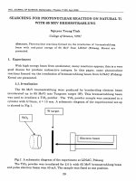
Fig. 2. Schematic design of device and measurement setup. A battery operated
high voltage generator is connected to parallel pin electrodes and the ion wind is
measured by hotwires heated by constant current.
3. Design and experimental setup
In order to show the flow generation capability of the device,
we designed and fabricated a transparent prototype made by
polypropylene with a mechanical precision of 20 m as shown in
Fig. 2. The internal cross section is 15 mm height × 20 mm width.
The pin electrodes are held, aligned and positioned at one end of
the device. All parts are designed for mechanical assembly via press
fitting and a small amount of conformal coating is applied at the
electrode holder to ensure electric isolation.
The electrodes are stainless steel SUS304, each 8 mm long and
0.4 mm in diameter, and placed in parallel with each other. The
spherical radius of the pin tip is approximately 80 m. The distance between the pins is adjustable with experiments carried out
at 5 mm, 7 mm and 9 mm separation.
For the electronics part, a high voltage generator (Kyoshin Denki
Ltd.), battery operated, capable of generating 10 kV direct current is connected to the pins. The discharge current is recorded
at the negative electrode by a precision measuring circuit, which
is integrated in the high voltage generator. The system is calibrated with high voltage generator and high voltage meter (Japan
Finechem Ltd.). The isolation between the electrodes is guaranteed
by two polypropylene (PP) blocks with leak current <10 nA measured between the electrode contact points. Because of the isolation
from external sources, the current at both electrodes is equal in size
as dictated by Kirchhoff’s current law.
The ion wind generated in the device is measured by an array of
8 hotwires placed across the downstream channel starting from a
distance of 12.5 mm downstream and is aligned in the plane of the
electrodes. The spacing between the hotwires is 2.5 mm thus the
hotwire array in total monitors a range of 17.5 mm streamwise. The
hotwire, made of gold, is bonded to the electric stands embedded
in the device’s body for signal reading. The hotwire has a diameter
of 25 m and length of 24 mm, and its temperature coefficient of
resistance is measured as 3700 ppm/◦ C.
By comparing the discharge I–V characteristics with and without the existence of hotwires, the minimum distance of 12.5 mm
was confirmed to not have any influence on the discharge itself.
The measurement of I–V characteristic of the device is repeated 8
times, corresponding to each velocity monitoring at each hotwire.
The hotwires are alternatively turned on to prevent the cross effect
of heat transfer between them. The hotwire is heated by constant
current of 0.2 A and its voltage is read out by a digital multimeter. Data is streamed to the computer using a LabVIEW DAQ6220
data acquisition system with a sampling rate of 1 Hz. Conversion
from the hotwire voltage to average air velocity is calculated by a
self-developed C-code routine.
In addition, the net charge of the released ion wind is measured using an aerosol electrometer 3068 (TSI). The results were
also recorded at 1 Hz and averaged over every 60 s. All the mea-
V.T. Dau et al. / Sensors and Actuators A 244 (2016) 146–155
149
Fig. 3. (a) Fabricated device showing pin electrodes and hotwires, (b) the bipolar corona simultaneously seen at both pin tips, (c)–(e) corona glows at different discharge
currents.
surements were carried out at 24 ◦ C and 55% relative humidity at
atmospheric pressure.
Fig. 3 shows pictures of the prototype in operation, where the
bipolar corona discharge is observable at both pin electrodes. The
observed corona glows reveal that the pin tips are similar to a
sphere partly embedded into the pin body and only a small partition
at the top hemisphere is unembedded and thus has extremely high
curvature, which focuses the electric field outwards and almost
parallel to the pin axis.
4. Numerical modeling of the device
Many numerical analyses have been carried out to understand
the EHD flow in different discharge configurations. Those studies
solved mass and momentum conservation equations (flow field)
coupled with the Poisson and charge conservation equations (electric and charge fields). For the unipolar corona discharge mode,
various EHD flow simulations for different electrode geometries
were carried out for the steady-state flow [17,70,71]. On the other
hand, sophisticated bipolar simulations were performed for the
glow discharge [72], aerodynamic flow control [73] and a review
of numerical studies of EHDs can be seen in the work of Adamiak
[74]. In this part, to avoid the complications of modeling of the
discharge itself, we deploy multi physics simulation to analyse the
flow characteristics of our system by treating the corona as a boundary condition.
The electric field E is represented as the gradient of an electric
potential V, E = −∇ V calculated by Gauss’ law and is written by the
Poisson equation:
∇ .E = −∇ 2 V = q/ε0
(1)
where ε0 is the permittivity of free space and q = q+ − q− is the
total charge of from the positive and negative pins.
The charge drift creates a total electric current density J, without
considering the external bulk flow and neglecting the ion diffusion,
the total electric current density is the sum of the positive and negative current density J = → J+ + → J− = ± q± E + q± U (where is
mobility of charge). Because the total charge is conserved, the total
current density has a zero divergence ∇ .J = 0. The continuity of the
positive/negative current density is described by the ion recombination, which is Ri q+ q /qe (where Ri and qe are ion recombination
rate and electron charge).
→ J± = ± q± E + q± U
(2-1)
∇ .→ J± = ∓Ri q+ q /qe
(2-2)
∇ . (→ J+ + → J− ) = 0
(2-3)
For the fluidic aspect, the flow is assumed to be incompressible
Newtonian fluid and is considered at steady state. The buoyancy
force due to temperature variations is neglected. The flow is then
described by the Navier–Stokes equations, including conservations
of momentum and of mass density. The impact of the electric field
Fig. 4. Meshing and boundary conditions for numerical setup of device. The inset shows the meshing at electrode tip vicinity.
150
V.T. Dau et al. / Sensors and Actuators A 244 (2016) 146–155
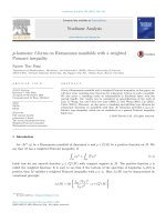
Fig. 5. (a) I–V of bipolar configuration for electrode span = 5, 7, 9 mm and (b) relation of
to the momentum of the gas is described by the volume force qE on
the right-hand side of Eq. (3),
∇ . U U − ϑ∇ . ∇ U = −∇ p + qE/
(3)
∇ .U = 0
(4)
The solutions of Eqs. (1)–(4) are obtained by the development of
a solver in the finite volume library OpenFOAM [75]. For a typical
corona discharge, the electric field magnitude E is of the order of
√
I − V (b). The error bar is standard deviation from 8 repeats.
106 V m−1 which yields the drift velocity E ≈ 100 m s−1 . This is
much larger than the air velocity U, which is of the order of several
m s−1 . Therefore, the term q+ U in Eq. (2-1) is neglected. For stable
simulation, an additional solver was developed to solve Eqs. (1) and
(2) only to provide the initial electric field condition for the coupled
Eqs. (1)–(4) in the main solver.
The simulation domain was modelled as shown in Fig. 4. The
non-slip, no-penetration fluidic condition was set on the wall of
the pin electrode and the free condition was used for the other
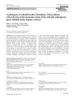
Fig. 6. (a) Simulated flow stream line and (b) flow pattern visualized by smoke.
V.T. Dau et al. / Sensors and Actuators A 244 (2016) 146–155
151
boundaries. For the electric field, voltage was applied to the boundary of the electrodes and the Neumann condition was applied at the
edges of the domain. At the electrode, we assumed that the corona
discharge maintained a constant ion density ±
±
= I/ ( Ew A)
(5)
where A is the total area of the tip. The electric field at the wall
tip Ew is determined based on Peek’s law for the barbed wire with
spheroidal tip for air at standard condition, without correction for
surface roughness and pressure dependency as [76]:
Ew = 27.2 kV/cm
1 + 0.54/R1/2
(6)
where R is the radius of the tips in units of meters. Alternatively,
for the case of an arbitrary shape with double curvature, the formula differs only by a factor of 1/2 to the radius of curvature Ew =
31 kV/cm
1 + 0.308/(0.5R)1/2
[77]. By applying both equa-
tions for our configuration, we can conclude that the threshold
difference is small, around 5%. Finally, with air used as the media,
the following constants close the modeling portion: ε0 = 8.854 ×
10−12 C V−1 m−1 , Ri = 10−13 m3 s−1 , qe = 1.62 × 10⁻¹⁹ C, = 1.6 ×
.
10−4 m2 V−1 s−1 ,
= 1.2041 kg m−3 andv = 15.7 × 10⁻³ m2 .
5. Results and discussion
5.1. I–V characteristics
Fig. 5a shows the I–V characteristics of the system. In unipolar
corona discharge, the relationship I/V ∝ V (Townsend relationship)
is typically used in the analysis of various configurations including
point-to-plane [78], point-to-grid [79] or point-to-ring [80]. We
found that the
√ I–V in our configuration better matches with the
relationship I ∝ V as shown in Fig. 5b. The match is especially
accurate for electrode spans 7 mm and 9 mm, and is less followed
with 5 mm. Although this relation is much less common in comparison with the Townsend relationship, this is however in agreement
with the reported literature for some restricted tests, for example
in point-to-plane for the positive corona with electrode distance
50 mm [81] or spherically
√ symmetric unipolar corona [82]. In this
work, the relationship I ∝ V is used to analyse the present configuration in the next sections.
5.2. Flow pattern and net charge of ion wind
Fig. 6a presents the simulated result of the flow field. In order
to facilitate the discussion, a Cartesian coordinate system is designated with the origin located at the centre of electrode interspace
as shown in Fig. 6a. After being generated in the vicinity of the
tips, the ion clouds gain an initial momentum to move in the direction away from the pin tips and in parallel with the electrodes.
Under the interaction with the electric field between the two electrodes, the jets of oppositely charged ions tend to impinge on each
other at the middle of the electrode interspace, resulting in pressure drop and charge neutralization. This causes the bulk flow of
ions to move forward. The overall view of the generated ion wind
demonstrates that the jet flow is maintained downstream far away
from the pins. Fig. 6b shows the visualization of ion wind by smoke
particles introduced to the device from both sides of pins. Without applied voltage, the smoke remains almost stationary, slowly
diffusing inside the device (Fig. 6b, left). When the device is in operation and ion wind is generated, the two jet flows are demonstrated
by smoke movement as shown in Fig. 6b (right).
It was confirmed that as a result of the mixing
of opposite charges, the total charge of the ion wind
outside the wind collector was very low. It was typically around
Fig. 7. Velocity measured by hotwire with electrode span of (a) 5 mm, (b) 7 mm,
and (c) 9 mm.
−10 fA to +30 fA on the aerosol electrometer measured at outlet
of device. This charge was almost independent of the electrode
separation in experiments and is comparable with the value of the
background noise, which was measured with the device turned off.
Since this net charge of ion wind is very small compared with the
discharge current (of the order of A, which is 9 orders larger), this
confirms that the positive and negative charges are well balanced.
152
V.T. Dau et al. / Sensors and Actuators A 244 (2016) 146–155
Fig. 8. Velocity profile at hotwire position, electrode distance 7 mm, discharge current 5.37 A.
Fig. 10. Relation between hotwire output voltage and discharge current. The right
axis shows the average velocity calculated from hotwire voltage.
h = 1.02Ra0.1
Fig. 9. Comparison of simulation and experiment. Electrode distance 7 mm, discharge current 5.37 A, hotwire current 0.2 A.
5.3. Flow measurement by hotwire
The effect of ion wind on the temperature of the hotwire Thw ,
heated by the current Ihw is determined from the equilibrium equation of heat transfer at steady state between the hotwire and air
2
Ihw
Rhw = hAhw (Thw − Ta )
(7)
where Ahw , h, and Ta are surface area of the hotwire, heat transfer coefficient, and ambient temperature, respectively. Rhw is the
hotwire resistance expressed as
Rhw = Ra [1 + ˛ (Thw − Ta )]
(8)
with Ra and ␣ are the resistance at temperature Ta and the
temperature coefficient of the resistance of the hotwire material,
respectively.
Without corona discharge, stationary air defines the initial state
of measurement by natural convection. When the corona is activated, the ion wind cools the hotwire down by forced convection.
The heat transfer coefficient of forced convection [83] and natural
convection [84] are respectively calculated as presented in Eqs. (9)
and (10)
h = 0.24 + 0.56Re0.45
D
(9)
D
(10)
where Ra is the Rayleigh number, D is the effective diameter of
the hotwire, and Re = UD/ is the Reynolds number. The output
voltage on the hotwire, offset to the initial value measured with
still air, is measured as Vhw = Ihw Rhw = Ihw ˛ T . This voltage Vhw
is shown in Fig. 7.
Electrode span of s = 5 mm creates lower velocity than the others
and the flow is more unstable (see Fig. 7a). This is because as the pin
separation decreases, the electrode itself becomes significant compared with the interelectrode space. Intuitively when the electrode
span becomes comparable with the electrode radial dimension,
the flow component towards the counter electrode increases, and
the attack angle formed by two jet flows becomes larger. In other
words, the flow velocity component towards the counter electrode
becomes stronger. This results in a more direct collision of jet flows
from the pins, introducing turbulence and reducing the streamwise
flow velocity.
The above explanation is confirmed again with results in Fig. 7b
and c where the electrode span is 7 mm and 9 mm, respectively.
The measurement is more repeatable between different hotwires.
Hotwires placed further away from the electrodes have smaller
output voltage, which reflects the decay of the jet flow. The flow
velocity is slightly larger with increasing electrode separation,
however there is not much difference between 7 mm and 9 mm.
The flow velocity profile, which cannot be revealed by hotwire
anemometry, is demonstrated from simulation.
The profiles of the velocity along streamwise direction at eight
hotwire locations are plotted in Fig. 8 for electrode span of 7 mm,
discharge current I = 5.37 A and discharge voltage V = 5 kV. From
Fig. 8, it is evident that the peaks of the profiles decrease with
increasing streamwise distance from the pin tips. This confirms that
the jet decays with increasing distance from its source, as expected.
The tails of these profiles have negative values, which show that
there is a circulatory flow in the channel. A flow peak velocity up
to 1.8 m s−1 is achieved. The figure implies that the device can create bulk flow movement with typical jet flow characteristics. This
characteristic of the device allows us to further develop multi axis
inertial units, or multi direction synthetic jets in the future.
Fig. 9 compares the hotwire anemometry result elicited in the
experiment and the above simulation. The abscissa is the hotwire
position and the vertical axis is the output voltage in millivolts. For
direct comparison, the simulation values are expressed in terms of
hotwire voltage. As it can be seen, the simulation agrees well with
experiment. It is noted that because the hotwire is placed across the
entire width of the device, its measurement represents the cooling
V.T. Dau et al. / Sensors and Actuators A 244 (2016) 146–155
effect of the average flow velocity in hotwire plane, thus although
the peak velocity decays rapidly with distance, the average velocity
across the device and thus the output voltage on the hotwire decays
much slower.
It is also important to note that while ion is discharged with current of several As, the current supplied to hotwire is six orders
larger, so the effect of discharge current to the hotwire voltage
is very small. In addition, because both charges are released, this
error is further minimized and is negligible, therefore the voltage
on hotwire can be calculated by only considering the cooling effect
of the flow. This is further confirmed by turning on the corona discharge without heating the hotwire, when we observed zero output
voltage.
However there was still a difference with the experimental
results, particularly at the wire closest to the pin. Because the
experimental device was fabricated with limited resolution, the
device wall surface was unsmooth at a submillimeter scale and
it was excluded from the simulation. Also the pin holder, which
indeed has considerable size compared with the chamber although
its location at upstream would scale down its impact, is ignored
in the simulation. Finally the tolerance in pin alignment made the
tolerance at the closest hotwire larger compared with the others.
Better agreement can be expected if a microfabrication process is
involved.
Fig. 10 presents the relationship between the output voltage
on the hotwire, which is proportional to the average flow velocity,
and the discharge current. The result shows that the output voltage has√a linear relation with the square root of discharge current
Vhw ∝ I. Because the relation of the flow velocity and discharge
current can be estimated by the balance of kinetic energy of moving flow with discharge power, thus can be represented by hotwire
anemometry in our√device. It can be noted that, in the experiment,
the relation Vhw ∝ I also holds for all electrode spans. The power
for corona discharge itself is small, for example around 25 mW and
the power consumption of our electric circuit is less than 70 mW
for the experimental condition in Fig. 9.
6. Conclusion
We have presented the design of a bipolar corona-based airflow
generator and examined its characteristics by numerical simulations and experimental validation. The modified airflow generator
is based on the simultaneous generation of both positive and negative ions using two sharp electrodes placed in parallel. The resulting
neutralized ion wind is created with low power consumption. The
model showed good agreement with experimental data in terms
of the dynamic response. Based on the measured current–voltage
curves of bipolar corona discharge, simulations of flow rate and
charge distribution were carried out. The measured result of the
present device has slight discrepancy with experimental data particularly at close vicinity around the electrodes. We believe that
this mismatch can be improved with better fabrication process and
more precise simulation of boundary conditions. The ion diffusion
was not taken into account and the positive and negative coronas
and their induced ions were treated equally, which is different from
reality. In this regard many improvements are in progress, such as
more precise simulation of the electron-ion interaction plane.
Although in theory the system is expected to have increased
efficiency as the distance between the electrodes is reduced, this is
limited by the geometrical constraints of the system setup. The pins
and electrical connections still have finite size, impeding the airflow
around the pins. It is believed that with a revised system setup, such
as usage of pins with smaller diameters or utilization of a microfabrication process, the efficiency could further increase and ion
wind generation of similar magnitude could be expected at lower
153
voltage levels and reduced applied power. In addition, as for any
corona-based device, external factors such as temperature, humidity and atmospheric pressure will also affect the device and need
to be considered to ensure reliable operation. These improvements
are currently in progress and will be reported in future publications.
References
[1] L.Y. Yeo, H.-C. Chang, P.P.Y. Chan, J.R. Friend, Microfluidic devices for
bioapplications, Small 7 (2011) 12–48, />201000946.
[2] D.J. Laser, J.G. Santiago, A review of micropumps, J. Micromech. Microeng. 14
(2004) R35–R64, />[3] L. Chen, Fabrication and characterization of a multi-stage electroosmotic
pump for liquid delivery, Sens. Actuators B Chem. 104 (2005) 117–123, http://
dx.doi.org/10.1016/j.snb.2004.05.013.
[4] S. Yokota, A review on micropumps from the viewpoint of volumetric power
density, Mech. Eng. Rev. 1 (2014), />2014dsm0014, DSM0014–DSM0014.
[5] V.T. Dau, T.X. Dinh, T. Katsuhiko, S. Susumu, A cross-junction channel
valveless-micropump with PZT actuation, Microsyst. Technol. 15 (2009)
1039–1044, />[6] C.G.J. Schabmueller, M. Koch, M.E. Mokhtari, A.G.R. Evans, A. Brunnschweiler,
H. Sehr, Self-aligning gas/liquid micropump, J. Micromech. Microeng. 12
(2002) 420–424, />[7] K. Tanaka, V.T. Dau, R. Sakamoto, T.X. Dinh, D.V. Dao, S. Sugiyama, Fabrication
and basic characterization of a piezoelectric valveless micro jet pump, Jpn. J.
Appl. Phys. 47 (2008) 8615–8618, />[8] D. Jang, K. Lee, Flow characteristics of dual piezoelectric cooling jets for
cooling applications in ultra-slim electronics, Int. J. Heat Mass Transf. 79
(2014) 201–211, />[9] V.T. Dau, T.X. Dinh, T.T. Bui, Jet flow generation in a circulatory miniaturized
system, Sens. Actuators B Chem. 223 (2015) 820–826, />1016/j.snb.2015.09.151.
[10] V.T. Dau, T.X. Dinh, Numerical study and experimental validation of a
valveless piezoelectric air blower for fluidic applications, Sens. Actuators B
Chem. 221 (2015) 1077–1083, />[11] O.M. Stuetzer, Ion drag pumps, J. Appl. Phys. 31 (1960) 136–146, .
org/10.1063/1.1735388.
[12] V.V. Gogosov, G.A. Shaposhnikova, I.D. Shikhmurzaev, Qualitative analysis of
electro-hydrodynamic characteristics of weakly conducting fluids, J. Appl.
Math. Mech. 46 (1982) 339–346, />[13] Y. Otsubo, K. Edamura, Dielectric fluid motors, Appl. Phys. Lett. 71 (1997)
318–320, />[14] R.V. Raghavan, J. Qin, L.Y. Yeo, J.R. Friend, K. Takemura, S. Yokota, et al.,
Electrokinetic actuation of low conductivity dielectric liquids, Sensors
Actuators B Chem. 140 (2009) 287–294, />04.036.
[15] T.C. Corke, C.L. Enloe, S.P. Wilkinson, Dielectric barrier discharge plasma
actuators for flow control, Annu. Rev. Fluid Mech. 42 (2010) 505–529, http://
dx.doi.org/10.1146/annurev-fluid-121108-145550.
[16] A. Rashkovan, E. Sher, H. Kalman, Experimental optimization of an electric
blower by corona wind, Appl. Therm. Eng. 22 (2002) 1587–1599, http://dx.
doi.org/10.1016/S1359-4311(02)00082-0.
[17] C. Kim, K.C. Noh, S.Y. Kim, J. Hwang, Electric propulsion using an alternating
positive/negative corona discharge configuration composed of wire emitters
and wire collector arrays in air, Appl. Phys. Lett. 99 (2011) 2013–2016, http://
dx.doi.org/10.1063/1.3636409.
[18] D.I. Carroll, I. Dzidic, R.N. Stillwell, K.D. Haegele, E.C. Horning, Atmospheric
pressure ionization mass spectrometry. Corona discharge ion source for use in
a liquid chromatograph–mass spectrometer-computer analytical system,
Anal. Chem. 47 (1975) 2369–2373, />[19] A. Das Gupta, S. Roy, Noise control of subsonic cavity flows using plasma
actuated receptive channels, J. Phys. D Appl. Phys. 47 (2014) 502002, http://
dx.doi.org/10.1088/0022-3727/47/50/502002.
[20] M. Meziane, O. Eichwald, J.P. Sarrette, O. Ducasse, M. Yousfi, F. Marchal,
Electro-hydrodynamics and kinetic modelling of polluted air flow activated
by multi-tip-to-plane corona discharge, J. Appl. Phys. 113 (2013) 153302,
/>[21] B. Chua, A.S. Wexler, N.C. Tien, D.A. Niemeier, B.A. Holm, Collection of liquid
phase particles by microfabricated electrostatic precipitator, J.
Microelectromech. Syst. 22 (2013) 1010–1019.
[22] A.S. Chua, N.C. Tien, D.A. Niemeier, B.A. Holmén, Micro corona based particle
steering air filter, Sens. Actuators A Phys. 196 (2013) 8–15, />10.1016/j.sna.2013.03.029.
[23] B. Chua, J.J. Pak, Miniaturized corona flow sensor operating in drift mobility
increment mode for low flow velocity measurement, Sens. Actuators A Phys.
224 (2015) 65–71, />[24] A.K. Sen, J. Darabi, D.R. Knapp, Design, fabrication and test of a microfluidic
nebulizer chip for desorption electrospray ionization mass spectrometry,
Sens. Actuators B Chem. 137 (2009) 789–796, />2009.02.002.
154
V.T. Dau et al. / Sensors and Actuators A 244 (2016) 146–155
[25] V.T. Dau, T.T. Bui, T.X. Dinh, T. Terebessy, H.T. Phan, Absolute pressure sensing
with bipolar corona discharge: design, simulation and experimental
validation, 29th IEEE Int. Conf. Micro. Electro. Mech. Syst. (2016) 820–823.
[26] A. Belinger, N. Naudé, J.P. Cambronne, D. Caruana, Plasma synthetic jet
actuator: electrical and optical analysis of the discharge, J. Phys. D Appl. Phys.
47 (2014) 345202, />[27] S. Liu, C. Huang, C. Shen, H. Jiang, Y. Chu, A novel driving mode for ion shutter
based on alternating current superposition and its application to ion mobility
spectrometry, Sens. Actuators B Chem. 211 (2015) 102–110, />10.1016/j.snb.2015.01.061.
[28] B. Chua, V.J. Logeeswaran, M. Chan, H. Park, D.A. Horsley, N.C. Tien, Wideband
mechanical excitation by a microcorona-driven vibrating element, J.
Microelectromech. Syst. 24 (2015) 224–231.
[29] G. Pardon, L. Ladhani, N. Sandström, M. Ettori, G. Lobov, Aerosol sampling
using an electrostatic precipitator integrated with a microfluidic interface,
Sensors Actuators B. Chem. 212 (2015) 344–352, />snb.2015.02.008.
[30] B. Chua, A.S. Wexler, N.C. Tien, D.A. Niemeier, B.A. Holmen, Electrical mobility
separation of airborne particles using integrated microfabricated corona
ionizer and separator electrodes, J. Microelectromech. Syst. 18 (2009) 4–13,
/>[31] B.L. Henson, Toward a fundamental model for steady point-plane corona
discharges, J. Appl. Phys. 55 (1984) 150–157, />332878.
[32] I.Y. Chen, M.Z. Guo, K.S. Yang, C.C. Wang, Enhanced cooling for LED lighting
using ionic wind, Int. J. Heat Mass Transf. 57 (2013) 285–291, .
org/10.1016/j.ijheatmasstransfer.2012.10.015.
[33] A.M. Drews, L. Cademartiri, G.M. Whitesides, K.J.M. Bishop, Electric winds
driven by time oscillating corona discharges, J. Appl. Phys. 114 (2013), http://
dx.doi.org/10.1063/1.4824748.
[34] D.B. Go, S.V. Garimella, T.S. Fisher, R.K. Mongia, Ionic winds for locally
enhanced cooling, J. Appl. Phys. 102 (2007), />2776164.
[35] P.J. McKinney, J.H. Davidson, D.M. Leone, Current distributions for barbed
plate-to-plane coronas, IEEE Trans. Ind. Appl. 28 (1992) 1424–1431, http://dx.
doi.org/10.1109/28.175297.
[36] B. Komeili, J.S. Chang, G.D. Harvel, C.Y. Ching, D. Brocilo, Flow characteristics
of wire-rod type electrohydrodynamic gas pump under negative corona
operations, J. Electrostat. 66 (2008) 342–353, />elstat.2008.02.004.
[37] H. Toyota, S. Zama, Y. Akamine, S. Matsuoka, K. Hidaka, Gaseous electrical
discharge characteristics in air and nitrogen at cryogenic temperature, IEEE
Trans. Dielectr. Electr. Insul. 9 (2002) 891–898, />TDEI.2002.1115482.
[38] P. Zhao, S. Portugal, S. Roy, Efficient needle plasma actuators for flow control
and surface cooling, Appl. Phys. Lett. 107 (2015) 033501, />1063/1.4927051.
[39] B. Kim, S. Lee, Y.S. Lee, K.H. Kang, Ion wind generation and the application to
cooling, J. Electrostat. 70 (2012) 438–444, />2012.06.002.
[40] J. Darabi, C. Rhodes, CFD modeling of an ion-drag micropump, Sens. Actuators
A Phys. 127 (2006) 94–103, />[41] L. Li, S.J. Lee, W. Kim, D. Kim, An empirical model for ionic wind generation by
a needle-to-cylinder dc corona discharge, J. Electrostat. 73 (2015) 125–130,
/>[42] O. Fawole, M. Tabib-Azar, A novel geometry for a corona wind
electrohydrodynamic pump, IEEE Sensors 2014 Proc., IEEE (2014) 452–454,
/>[43] M. Riherd, S. Roy, Measurements and simulations of a channel flow powered
by plasma actuators, J. Appl. Phys. 112 (2012) 053303, />1063/1.4749250.
[44] K. Nishiyama, H. Kuninaka, Discussion on performance history and operations
of hayabusa ion engines, Trans. Japan Soc. Aeronaut. Sp. Sci. Aerosp. Technol.
Japan 10 (2012) Tb 1–Tb 8, 1.
[45] D.M. Goebel, I. Katz, Fundamentals of Electric Propulsion: Ion and Hall
Thrusters, John Wiley & Sons, Hoboken, New Jersey, 2008.
[46] V.T. Dau, T. Shiozawa, D.V. Dao, H. Kumagai, S. Sugiyama, A dual axis gas
gyroscope utilizing low-doped silicon thermistor, 18th IEEE Int. Conf. Micro
Electro Mech. Syst. 2005. MEMS 2005 (2005) 626–629, />1109/MEMSYS.2005.1454007.
[47] R.B. Schlesinger, M. Lippmann, Particle deposition in the trachea: in vivo and
in hollow casts, Thorax 31 (1976) 678–684, />6.678.
[48] Y. Fukatsu, E. Nomura, K. Matsu, Gas rate gyro, US4941353, 1990.
[49] V.T. Dau, T. Otake, T.X. Dinh, D.V. Dao, S. Sugiyama, A multi axis fluidic inertial
sensor, Proc. IEEE Sensors, IEEE (2008) 666–669, />ICSENS.2008.4716529.
[50] E.-H. Lee, B. Chua, A. Son, Micro corona discharge based cell lysis method
suitable for inhibitor resistant bacterial sensing systems, Sens. Actuators B
Chem. 216 (2015) 17–23, />[51] B. Chua, A. Son, Sterilization of Escherichia coli O157:H7 using micro corona
ionizer, Biomed. Microdevices 16 (2014) 355–363, />s10544-014-9838-4.
[52] V.N. Morozov, Generation of biologically active nano-aerosol by an
electrospray-neutralization method, J. Aerosol Sci. 42 (2011) 341–354, http://
dx.doi.org/10.1016/j.jaerosci.2011.02.008.
[53] J.C. Almekinders, C. Jones, Multiple jet electrohydrodynamic spraying and
applications, J. Aerosol Sci. 30 (1999) 969–971, />S0021-8502(98)00755-1.
[54] D. Camelot, J.C.M. Marijnissen, B. Scarlett, Bipolar coagulation process for the
production of powders, Ind. Eng. Chem. Res. 38 (1999) 631–638, .
org/10.1021/ie980435j.
[55] O. Salata, Tools of nanotechnology: electrospray, Curr. Nanosci. 1 (2005)
25–33, />[56] V.T. Dau, D. Viet Dao, S. Sugiyama, A 2-DOF convective micro accelerometer
with a low thermal stress sensing element, Smart Mater. Struct. 16 (2007)
2308–2314, />[57] D.V. Dao, V.T. Dau, T.X. Dinh, S. Sugiyama, A fully integrated MEMS-based
convective 3-DOF gyroscope, Transducers 2007–2007 Int. Solid-State Sensors,
Actuators Microsystems Conf., IEEE (2007) 1211–1214, />1109/SENSOR.2007.4300354.
[58] V.T. Dau, T.T. Bui, T.X. Dinh, T. Terebessy, Pressure sensor based on bipolar
discharge corona configuration, Sens. Actuators A Phys. 237 (2016) 81–90,
/>[59] Y. Cai, Y. Zhao, Ion discharge gyroscope, US8146423, 2012.
[60] V.T. Dau, D.V. Dao, T. Shiozawa, S. Sugiyama, Simulation and fabrication of a
convective gyroscope, IEEE Sens. J. 8 (2008) 1530–1538, />1109/JSEN.2008.925457.
[61] T. Shiozawa, V.T. Dau, D.V. Dao, H. Kumagai, S. Sugiyama, A dual axis thermal
convective silicon gyroscope, Micro-Nanomechatronics Hum. Sci. 2004
Fourth Symp. Micro-Nanomechatronics Information-Based Soc. 2004., IEEE
(2004) 1–6, />[62] V.T. Dau, D.V. Dao, T. Shiozawa, H. Kumagai, S. Sugiyama, A single-axis
thermal convective gas gyroscope, Sens. Mater. 17 (2005) 453–463.
[63] H. Chang, P. Zhou, Z. Xie, X. Gong, Y. Yang, W. Yuan, Theoretical modeling for a
six-DOF vortex inertial sensor and experimental verification, J.
Microelectromech. Syst. 22 (2013) 1100–1108, />JMEMS.2013.2271862.
[64] G.T. Roman, R.T. Kennedy, Fully integrated microfluidic separations systems
for biochemical analysis, J. Chromatogr. A 1168 (2007) 170–188, .
org/10.1016/j.chroma.2007.06.010, Discussion 169.
[65] X. Wang, L. Yi, N. Mukhitov, A.M. Schrell, R. Dhumpa, M.G. Roper,
Microfluidics-to-mass spectrometry: a review of coupling methods and
applications, J. Chromatogr. A 1382 (2015) 98–116, />j.chroma.2014.10.039.
[66] F. Haghighi, Z. Talebpour, A. Sanati-Nezhad, Through the years with on a chip
gas chromatography: a review, Lab Chip 15 (2015) 2559–2575, .
org/10.1039/C5LC00283D.
[67] V.T. Dau, T.X. Dinh, D.V. Dao, S. Sugiyama, Design and simulation of a novel
3-DOF MEMS convective gyroscope, IEEJ Trans. Sens. Micromach. 128 (2008)
219–224, />[68] W. Glover, H.-K. Chan, Electrostatic charge characterization of pharmaceutical
aerosols using electrical low-pressure impaction (ELPI), J. Aerosol Sci. 35
(2004) 755–764, />[69] L.F. Whitmore, J.F. Hughes, N. Harrison, M. Abela, P. O’Rourke, Enhanced
efficiency of electrostatically charged insecticide aerosols, Pest Manag. Sci. 57
(2001) 432–436, />[70] A.A. Martins, Simulation of a wire-cylinder-plate positive corona discharge in
nitrogen gas at atmospheric pressure, Phys. Plasmas 19 (2012), .
org/10.1063/1.4725499.
[71] C. Kim, K.C. Noh, J. Hyun, S.G. Lee, J. Hwang, H. Hong, Microscopic energy
conversion process in the ion drift region of electrohydrodynamic flow, Appl.
Phys. Lett. 100 (2012), />[72] K. Yanallah, F. Pontiga, A. Castellanos, Numerical simulation of an oxygen-fed
wire-to-cylinder negative corona discharge in the glow regime, J. Phys. D Appl.
Phys. 44 (2011) 055201, />[73] J.-C. Matéo-Vélez, P. Degond, F. Rogier, A. Séraudie, F. Thivet, Modelling
wire-to-wire corona discharge action on aerodynamics and comparison with
experiment, J. Phys. D. Appl. Phys. 41 (2008) 035205, />1088/0022-3727/41/3/035205.
[74] K. Adamiak, Numerical models in simulating wire-plate electrostatic
precipitators: a review, J. Electrostat. 71 (2013) 673–680, />1016/j.elstat.2013.03.001.
[75] OpenFOAM® | The OpenFOAM Foundation, (n.d.). />[76] F.W. Peek, Dielectric Phenomena in High Voltage Engineering, McGraw-Hill,
New York, 1978.
[77] M. Goldman, A. Goldman, Corona Discharges, Academic Press, Inc., 1978,
/>[78] M. Robinson, Movement of air in the electric wind of the corona discharge,
Trans. Am. Inst. Electr. Eng. Part I Commun. Electron. 80 (1961) 143–150,
/>[79] K. Yamada, An empirical formula for negative corona discharge current in
point-grid electrode geometry, J. Appl. Phys. 96 (2004) 2472–2475, http://dx.
doi.org/10.1063/1.1775301.
[80] P. Giubbilini, The current-voltage characteristics of point-to-ring corona, J.
Appl. Phys. 64 (1988) 3730–3732, />[81] A.F. Kip, Onset studies of positive point-to-plane corona in air at atmospheric
pressure, Phys. Rev. 55 (1939) 549–556, />55.549.
[82] R.S. Sigmond, Simple approximate treatment of unipolar
space-charge-dominated coronas: the Warburg law and the saturation
current, J. Appl. Phys. 53 (1982) 891–898, />
V.T. Dau et al. / Sensors and Actuators A 244 (2016) 146–155
[83] M. Mikheyev, Fundamentals of Heat Transfer, Peace Publisher, Moscow, 1968.
[84] I. Mabuchi, T. Tanaka, Experimental study on effect of vibration on natural
convective heat transfer from a horizontal fine wire, Bull. JSME 10 (1967)
808–816, />
Biographies
Van Thanh Dau received the B.S. degree in aerospace engineering from Hochiminh City University of Technology,
Vietnam, in 2002, and the M.S. and Ph.D. degrees in micromechatronics from Ritsumeikan University, Japan, in 2004
and 2007, respectively. From 2007 to 2009, he was a Postdoctoral Fellow with Japan Society for the Promotion of
Science (JSPS) at Micro Nano Integrated Devices Laboratory, Ritsumeikan University. Since 2010 he has been with
Research Group, Sumitomo Chemical Co., Ltd. where he
works on integrated micro electrospray and atomization
methods. His current research subjects are micro fluidics,
electro hydrodynamics, microsensors and microactuators.
He is the author and co-author of more than 70 scientific
articles and 19 inventions.
Thien Xuan Dinh received the B.S. degree in aerospace
engineering from Hochiminh City University of Technology in 2002, Vietnam and the M.Sc. and Ph.D. degrees in
mechanical engineering from Ritsumeikan University in
2004 and 2007, respectively. He was recipient of Japan
Government Scholarship (MEXT) for Outstanding Student
to pursuits his M. Sc. and Ph. D. courses and Japan Society
for the Promotion of Science postdoctoral fellowship from
2011 to 2013. His general research interest is computation
of fluid flow. The large parts of his research are turbulence
modeling using Large Eddy Simulation, multiphase modeling using Volume of Fluid technique, and simulation of
turbulence and dispersion. Recently, he has focused on
155
computation of fluid flow for developing microfluidic devices as electrohydrodynamics, microsensors, micropump, and micromixer for biochemical engineering.
Tibor Terebessy received his M.S. degree with honour in plasma physics from Comenius University, Slovakia, in 1998 and his Ph.D. degree in electronics engineering
from Shizuoka University, Japan, in 2002. He was then awarded a Postdoctoral
Fellowship by the Japan Society for the Promotion of Science (JSPS), continuing
his research in large area microwave discharges and their industrial applications
at Graduate School of Electronic Science and Technology, Shizuoka University,
Japan. His main areas of research interests include atmospheric pressure discharges,
microwave plasmas, nanoparticle generation and electrohydrodynamics. He is the
author and co-author of more than 20 scientific articles and 17 inventions.
Tung Thanh Bui received the B.S. degree in electrical
engineering from Vietnam National University, Hanoi
(VNUH) in 2004, and the M.E. and D.Eng. degrees in Science and Engineering from Ritsumeikan University, Shiga,
Japan, in 2008 and 2011, respectively. From 2011 to 2015
he was a post-doctoral researcher with the 3D Integration System Group, Nanoelectronics Research Institute
(NeRI), National Institute of Advanced Industrial Science
and Technology (AIST), Tsukuba, Japan. Currently, he is
an assistant professor at the Faculty of Electronics and
Telecommunication (FET), University of Engineering and
Technology (UET), Vietnam National University, Hanoi
(VNUH). His current research interests are 3D system integration technology and MEMS based sensors, actuators and applications. He is the
author and co-author of more than 60 scientific articles and 7 inventions.