Volume 1 photovoltaic solar energy 1 18 – chalcopyrite thin film materials and solar cells
Bạn đang xem bản rút gọn của tài liệu. Xem và tải ngay bản đầy đủ của tài liệu tại đây (2.37 MB, 24 trang )
1.18
Chalcopyrite Thin-Film Materials and Solar Cells
T Unold and CA Kaufmann, Helmholtz Zentrum für Materialien und Energie GmbH, Berlin, Germany
© 2012 Elsevier Ltd.
1.18.1
1.18.2
1.18.2.1
1.18.2.2
1.18.2.3
1.18.2.3.1
1.18.3
1.18.3.1
1.18.3.1.1
1.18.3.1.2
1.18.3.1.3
1.18.3.2
1.18.3.3
1.18.4
1.18.4.1
1.18.4.1.1
1.18.4.1.2
1.18.4.1.3
1.18.4.2
1.18.4.3
1.18.4.4
1.18.4.5
1.18.5
1.18.6
References
Introduction
Material Properties
Structure
Optical Properties
Electrical Properties
Surfaces and grain boundaries
Deposition Methods
Single-Step Deposition
Single-stage process
Two-stage process
Three-stage or multistage process
Sequential Deposition
General Considerations
Device Structure
Substrate
Glass
Metal substrates
Polyimide substrates
Barrier Layers
Back Contact
Buffer Layer
Front Contact
Device Properties
Outlook
399
400
400
401
403
405
406
407
407
407
407
408
410
410
410
410
411
412
412
412
412
414
414
417
418
1.18.1 Introduction
Chalcopyrite-type materials are currently considered to be the most promising thin-film solar cell materials, because they exhibit
direct band gaps well matched to the solar spectrum and because of their very favorable electronic properties that have recently led
to solar cell efficiencies surpassing 20%. The chalcopyrite crystal structure family lends its name from the mineral CuFeS2, which is
one of the most important copper (Cu) ores. Chalcopyrite-type materials comprise the compounds formed either from group I, III,
and VI (I-III-VI2) or from group II, IV, and V (II-IV-V2) elements of the periodic table [1].
Artificial chalcopyrite-type crystals were first synthesized and structurally characterized by Hahn et al. in the early 1950s [2]. The
optical and electrical properties of chalcopyrite-type crystals were investigated by Shay and Wernick at Bell labs in the 1970s,
originally for the application in optoelectronic devices [1]. First single-crystal homojunction devices based on CuInSe2 were realized
and electroluminescence was demonstrated also at Bell labs in 1974 by short anneals of n-type crystals in Se vapor [3]. The first
single-crystal solar cell based on CuInSe2 as an absorber material was demonstrated in the same year, using a CuInSe2/CdS
heterojunction device. This device, which contained a very thick, several micron n-type CdS as emitter window layer, showed a
photoconversion efficiency of 5% [4]. Soon after photoconversion, efficiencies above 10% were obtained by further optimization of
such device structures [5].
First real thin-film solar cells based on chalcopyrite-type absorbers were prepared by Kazmerski also using CuInSe2/CdS
heterojunctions [6]. These types of solar cells started to receive considerable attention when Mickelson et al. demonstrated solar
cells based on polycrystalline CuInSe2 absorber layers with an efficiency of 9.4% in 1981 by co-evaporation from elemental
sources [7]. Already in 1982, an impressive thin-film solar cell efficiency of 14.6% was reported by the same group by optimizing the
co-evaporation process [8]. Since then, a number of technological breakthroughs, such as the discovery of Na doping, alloying with
Ga, and replacing the thick CdS window layer by a thin CdS buffer and thick conductive ZnO window layer, have led to a current
record device efficiency of 20.3% for Cu(In,Ga)Se2-based thin-film solar cells [9].
Over the last 30 years, chalcopyrite materials and solar cells have been investigated by many groups worldwide, and we will
attempt to give an overview of the most salient findings and lessons learned with respect to these types of solar cells. Also industry
has been involved in research and commercialization of chalcopyrite solar cells early on starting with Boeing and ARCO Solar in the
1980s. Since then, large-scale production facilities for chalcopyrite-based thin-film photovoltaic modules have been built and
ramped up, with an estimated current capacity close to 1 GW year−1. Although m2-sized modules with record efficiencies of 17%
Comprehensive Renewable Energy, Volume 1
doi:10.1016/B978-0-08-087872-0.00121-9
399
400
Technology
have been demonstrated recently [10], there is still a considerable gap between efficiencies achieved on small area devices in the
laboratory and actual module efficiencies obtained in large-scale production. Here we will try to address the current state of
knowledge and relevant challenges for commercialization with respect to chalcopyrite-type solar cells. We would like to mention
that a number of excellent reviews on chalcopyrite-type materials and solar cells have been published previously, which may
provide additional information that is not covered in this chapter [11–17].
1.18.2 Material Properties
1.18.2.1
Structure
The crystal structure of chalcopyrite-type semiconductors can be derived from the diamond lattice in accordance with the
Grimm-Sommerfeld or 8-N rule [18]. This means that chalcopyrite semiconductors, just like group IV elements silicon or
germanium, exhibit tetrahedral bonding, that is, every atom has four nearest neighbors. In this review, we will restrict ourselves
to the Cu-chalcopyrite semiconductors formed from group I-III-VI elements. Starting from the sphalerite structure of ZnS (Figure 1),
the chalcopyrite lattice is obtained by the ordered substitution of the group II element (Zn) by the group I (Cu) and group III (In or
Ga) elements. This leads to a doubling of the unit cell in the c-direction, the so-called tetragonal crystal structure as shown in
Figure 1. Because of the different bond strength and bond lengths of the group I–VI and III–V bonds, the lattice parameter c in
general is not exactly 2a, which is also called the tetragonal distortion of the unit cell [1].
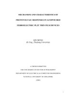
Because chalcopyrite-type materials consist of at least three elements, a number of different phases are possible depending on the
exact compositions and the growth conditions. In Figure 2, a ternary phase diagram with the corner points Cu, In, and Se is shown.
Because chalcopyrites are usually synthesized at sufficient chalcogen excess (here Se) the composition of, in this example CuInSe2,
the thin-film materials prepared at varying Cu/(In + Ga) composition usually conform to the tie-line spanned by Cu2Se and In2Se3.
The desired chalcopyrite phase in this diagram is at the center of the tie-line. As will be discussed further below, many deposition
techniques use this finding by moving from the In-rich to the Cu-rich side and back to an experimentally determined ideal
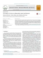
composition at the end of the process. An equilibrium pseudobinary phase diagram composed of a mixture of In2Se3 and Cu2Se,
corresponding to the tie-line in Figure 2 is shown in Figure 3 [19]. Observed phases are indicated as a function of growth
temperature: α denotes the chalcopyrite phase, β denotes ordered defect chalcopyrite phases, such as CuIn5Se8 or CuIn3Se5 and δ
is the sphalerite phase occurring only at high temperatures. It can be seen that there is a small region between stoichiometry and the
copper-poor side where single-phase chalcopyrite is obtained at 500 °C. This region narrows further for lower temperatures. On the
Cu-rich side, CuxSe phases segregate and on the Cu-poor side a coexistence of chalcopyrite and defect chalcopyrite phases is
expected. It is interesting to note that at low temperatures even for stoichiometric composition CuxSe phase segregation is expected,
which has to be considered in the design of growth processes for these compounds. It has been found that the width of the
chalcopyrite single-phase region is increased by alloying with gallium (Ga) and/or doping with Na [20].
Figure 1 Crystal structure of (ZnS) sphalerite and (CuInS2) chalcopyrite. Note that the unit cell is doubled in the c-direction for the chalcopyrite lattice.
Chalcopyrite Thin-Film Materials and Solar Cells
401
Se
0 100
10
90
20
80
CuSe2 30
70
60 In2Se3
40
%
%
CuSe 50
50 InSe
60
40
Cu2Se
In2Se
30
70
80
20
90
100
0
Cu
10
10
20
30
40
50
%
60
70
80
90
0
100
In
Figure 2 Ternary phase diagram for Cu–In–Se. The dashed line indicates the pseudobinary tie-line between Cu2Se and In2Se3. Material phases occurring
during different growth processes are indicated as black circles.
800
β+δ
Temperature (�C)
δ
600
β+γ
400
β
α+δ
α
α+β
α+
Cu2Se (HT)
200
α + Cu2Se (RT)
10
15
20
25
Cu content (at %)
30
Figure 3 Pseudobinary phase diagram for In2Se3–Cu2Se tie-line shown in Figure 2. The shaded area indicates the regions in the phase diagram relevant
to multistage coevaporation of high-efficiency chalcopyrite solar cells.
CuInSe2 can be readily alloyed with Ga and forms a solid solution CuIn1−xGaxSe2 over the whole composition range 0 < Ga/
(In + Ga) < 1. This means that lattice constants change continuously from the lattice constants for pure CuInSe2 to those of pure
CuGaSe2, in accordance with Vegards law [21] as illustrated in Figure 4. Note also that the c/a ratio, that is the tetragonal distortion,
changes with composition from a mismatch value of +1% on the CuInSe2 to −3.5% for CuGaSe2. For a Ga content of about x = 0.23,
the tetragonal distortion vanishes and c/a = 2.0. Recently, it has been found that for exactly this composition ratio (or c/a ratio) the
grain size is significantly enhanced in Cu(In,Ga)Se2 thin films [23].
1.18.2.2
Optical Properties
Chalcopyrite semiconductors have direct band gaps leading to large absorption coefficients α > 104 cm−1 above the band gap. This
fact makes these materials very suitable as absorber materials in thin-film solar cells, as only thicknesses of about 1–2 µm are needed
to absorb most of the above-band gap light from the solar spectrum, without the need for light trapping. Absorption coefficients of
some Cu-chalcopyrite materials are shown in Figure 5 [24]. The band gaps of Cu-chalcopyrite materials strongly depend on the
specific composition and range from about 1 to 2.7 eV [1]. The most researched photovoltaic material CuIn1−xGaxSe2 exhibits band
402
Technology
2.01
2.00
1.99
1.98
1.97
c/a ratio
44.4
44.6
44.8
45.0
45.2
45.4
45.6
45.8
220 Reflection (°)
26.8
27.0
27.2
27.4
27.6
112 Reflection (°)
800
900
1000
1100
1200
Band gap (nm)
1.0
1.1
0.0
1.2
0.2
1.3
1.4
Band gap (eV)
0.4
1.5
0.6
1.6
0.8
1.0
[Ga]/([In] + [Ga])
Figure 4 Structural and optical parameters of CuIn1−xGaxSe2 as a function of gallium content. Data from Suri DK, Nagpal KC, and Chadha GK (1989).
Journal of Applied Crystallography 22: 578 [21] and Ishizuka S, Sakurai K, Yamada A, et al. (2005). Japanese Journal of Applied Physics 44: L679–682 [22].
106
Wavelength (nm)
1200 1000 800
600
400
Absorption coeffcient (cm–1)
8
6
CulnSe2
4
CuGaSe2
CuInSe2
2
105
8
6
4
2
104
8
6
1.0
1.5
2.0
2.5
3.0
Energy (eV)
Figure 5 Absorption coefficients of CuInSe2, CuGaSe2, and CuInS2. Data from Scheer R and Schock HW (2011) Chalcogenide Photovoltaics: Physics,
Technologies, and Thin Film Devices. Weinheim, Germany: Wiley-VCH [16].
gaps between 1.04 and 1.68 eV [22, 24, 25]. The band gap of CuIn1−xGaxSe2 increases monotonically with Ga content with a very
small bowing between the end points. This functional dependence can be described by
Eg ðxÞ ¼ 1:0 þ 0:564x þ 0:116x2
½1
Chalcopyrite Thin-Film Materials and Solar Cells
403
EC
EV
Cu2Se
Cu(In,Ga)Se2
Cu(In,Ga)3Se5
Figure 6 Band line-up for Cu(In,Ga)Se2 and secondary phases for Cu(In,Ga)3Se5, Cu2Se.
The highest efficiencies with chalcopyrite solar cells have been achieved with a Ga content between 0.2
leading to an upward shift of the conduction band whereas the valence band stays at the same energetic position [25–27]. This fact is
important to consider when constructing band diagrams of CIGSe heterojunction devices. In state-of-the-art Cu(In,Ga)Se2 devices
grown by the three-stage co-evaporation method, a significant Ga gradient is found in the absorber layers. This means that the band
gap, and in particular the conduction band minimum, varies accordingly throughout the device. In addition to or instead of Ga,
sulfur can be added to CuInSe2 to widen the band gap of CuIn1−xGaxSe2. However, in contrast to the effect of Ga, the addition
of sulfur both lifts the conduction band and lowers the valence band [26]. For a number of industrially used deposition processes,
sulfur is added to CuIn1−xGaxSe2 in order to widen the band gap close to the heterojunction [28].
Defect chalcopyrite phases are observed on the Cu-poor side of the phase diagram of CuIn1−xGaxSe2, whereas CuxSe secondary phases
appear for Cu-rich growth conditions of CuIn1−xGaxSe2. This means that not only the structural and electronic properties of these phases
may be relevant for the final device performance, but also their optical properties, in particular there band gap and band line-up with
respect to the main chalcopyrite phase. The expected band line-up for CuIn1−xGaxSe2 is shown in Figure 6 where it can be seen that for Ga
contents of x ≈ 0.3 a perfect line-up of Cu2Se and mostly a lowered valence band maximum for the defect chalcopyrite compound is
expected [29]. This may be one of the keys why CuIn1−xGaxSe2 exhibits maximum efficiencies within this Ga-composition ratio.
1.18.2.3
Electrical Properties
Cu-based chalcopyrite materials can be made p- or n-type depending on composition and growth conditions, solely due to the
presence of intrinsic defects without the need for doping by external impurities. Cu(In,Ga)Se2 grown Cu-rich and under
chalcogen-excess is always found to be p-type [30]. N-type doping of CuInSe2 can be obtained for low Cu/In ratios. Also, conversion
of n-type CuInSe2 into p-type CuInSe2 by annealing in high Se pressure has been demonstrated [31]. Typical charge carrier densities
of Cu-poor Cu(In,Ga)Se2 used in solar cells grown on soda-lime glass are between 1015 cm−3 and 1017 cm−3. Since the Cu/(In + Ga)
ratio in these materials is usually between 0.8 and 0.9, large amounts of defects in the percent range must be present, despite the fact
that the measured charge carrier densities are much lower. This can be explained by the fact that Cu-poor chalcopyrite compounds
with large deviations from stoichiometry such that Cu/(In + Ga) < 1 are heavily compensated, with simultaneous formation of
acceptors and donors, and a corresponding much lower net carrier density [32]. Also, the net doping density is found to strongly
increase with the concentration of sodium incorporated in the films. This is shown in Figure 7 where the charge carrier density is
shown for Cu(In,Ga)Se2 deposited on polymide foil with different NaF precursor layer thicknesses [33]. The effect of sodium on the
net charge carrier density has been explained with a passivation of shallow donors such as InCu antisites [34], or an increase in the
acceptor density via NaIn antisite defects [35]. Also a catalytic effect of Na on the passivation of VSe vacancy donors by oxygen has
been discussed [36]. There is also evidence that Na acts preferentially at grain boundaries (GBs) rather than in the bulk of the
individual grains of the thin films [35, 37] and it has been found to significantly influence the diffusion of elements and
morphology of the chalcopyrite-type thin films [38].
In principle, there are 12 intrinsic defects possible in a ternary chalcopyrite: three vacancies, three interstitials, and six antisite
defects. Obviously, the quaternary Cu(In,Ga)Se2 or pentenary Cu(In,Ga)(S,Se)2 systems even provides for substantially more
possible defects. The formation of defects in thermal equilibrium can be described by defect chemical models with the formation
of the defects depending on the specific formation energies, the formation enthalpies, and the chemical potentials [39]. For charged
defects, the formation enthalpy also directly depends on the position of the Fermi-level during defect formation. It has been found
from density functional theory (DFT) calculations under most conditions the formation energy of the copper-vacancy in CuInSe2
and CuGaSe2 is very low and can be even negative, depending on the position of the Fermi level [40–42]. These calculations also
show that the defect transition levels for CuInSe2 can be rather shallow and that the formation of neutral defect pairs such as
2VCu-InCu is very likely [40]. The DFT calculations predict that the ionization levels of these defect pairs are pushed out of the band
gap, thus rendering them electronically inactive, in particular with respect to minority carrier recombination.
404
Technology
6
10 kHz
Room temperature
4
NDLCP (cm−3)
2
1015
8
6
4
0 nm NaF
4 nm NaF
8 nm NaF
16 nm NaF
2
1014
0
500
1000
1500
<x> Distance profiling (nm)
2000
Figure 7 Charge carrier density for Cu(In,Ga)Se2 solar cells obtained from drive-level capacitance profiling (DLCP) measurements at room temperature
for different Na contents. Figure from Caballero R, Kaufmann CA, Eisenbarth T, et al. (2009) The effect of NaF precursors on low temperature growth of
CIGS thin film solar cells on polyimide substrates. Physica Status Solidi a – Applications and Materials Science 206(5): 1049–1053 [33].
50
PL signal (arb. units)
(b)
60
CuGa Se2
Stoichiometric
Cu(In Ga ) = 0.88
Copper poor
DA2
40
30
φexc
20
10−4
DA1
PL signal (arb. units)
(a)
DA3
10
φexc
10−5
10−6
10−7
EXC
0
1.55
1.60
1.65
1.70
Optical energy (eV)
1.75
10−8
1.00
1.10
1.20
Optical energy (eV)
1.30
Figure 8 Low-temperature photoluminescence (T = 10 K) as a function of excitation intensity for (a) stoichiometric epitaxially grown CuGaSe2 (data from
Unold T and Gutay L (2011) Photoluminescence of thin film solar cells. In: Abou-Ras D, Kirchatz T, and Rau U (eds.) Advanced Characterization of Thin
Film Solar Cells. Wiley [51]) and (b) Cu-poor Cu(In,Ga)Se2.
Defects in chalcopyrite thin films have been investigated by admittance [43–46], Deep Level Transient Spectroscopy (DLTS) [47],
and photoluminescence measurements [48–51]. However, the unambiguous assignment of ionization energies to different defects
remains elusive, because of the large number of possibilities to assign a transition found with these measurements. Shallow defects
can be best observed by photoluminescence measurements, whereas deep defects can be observed by admittance, DLCP, or DLTS
measurements. As expected from the phase diagram shown in Figure 3, the defect physics is expected to differ significantly for the
Cu-rich versus the Cu-poor composition range for chalcopyrite solar cells. Low-temperature photoluminescence measurements of
stoichiometric CuGaSe2 show excitonic transitions and shallow donor–acceptor pair transitions at low temperatures, as shown in
Figure 8(a) for a an epitaxial thin film grown by metal-organic chemical vapor deposition (MOCVD) [51, 52]. Photoluminescence
measurements on Cu-poor grown Cu(In,Ga)Se2 films which lead to the highest conversion efficiencies in devices do not show
distinct, narrow defect transitions either at low temperatures or at room temperature as shown in Figure 8(b). As is typical for this
material only one or two very broad defect transitions without excitonic signatures are observed, with very strong shifts of the peak
energy with excitation intensity [32, 51, 53]. This has been interpreted as a signature of significant potential fluctuations present in
these films because of the high degree of compensation as discussed above.
Photoconductivity, admittance, and capacitance voltage measurements have shown metastable effects, such as persistent
conductivity after light soaking [54–56]. These metastabilities have been discussed in conjunction with metastabilities in the
current-voltage characteristics, such as the increase in open-circuit voltage upon illumination with AM1.5 light, which has been
observed for chalcopyrite solar cells and modules [57, 58]. The charge carrier density determined by capacitance profiling is found to
increase after light soaking [59]. Also application of a reverse bias has been shown to lead to an increase in the charge carrier density
and defect profile as measured by capacitance techniques [20]. There are a number of different models explaining these effects [56],
among them a DX-center model [60], photodoping of CdS [61], the presence of a p+-layer close to the heterointerface [62], and an
amphoteric defect model [63].
Chalcopyrite Thin-Film Materials and Solar Cells
405
Mobilities of charge carriers in chalcopyrite materials have been determined for single crystals and to a much lesser extent for
polycrystalline thin films. The mobilities are found to differ strongly for the single-crystal and polycrystalline materials, as can be
understood from the dominant role of GBs in the latter materials. As also found for other semiconductor materials, the mobilities
generally depend strongly on the measurement temperature and material’s composition. Hole mobilities for CuInSe2 up to
60 cm2 V−1 s−1 [48] at room temperature have been measured for single crystals, and much lower values around 1 cm2 V−1 s−1
have been obtained for polycrystalline thin films [50, 64, 65]. These values have been inferred mostly from Hall measurements,
which are difficult to interpret for polycrystalline and strongly compensated materials. Hole mobility values smaller than 1 cm2
V−1 s−1 have been inferred from time-of-flight techniques [66], which has been explained by trapping in a large density of subgap
states. Electron mobilities of up to 900 cm2 V−1 s−1 have been reported for CuInSe2 single crystals by Hall measurements [31]. The
determination of electron mobilities in polycrystalline thin films, which are usually p-type remains elusive.
1.18.2.3.1
Surfaces and grain boundaries
GBs generally are expected to cause increased recombination of minority carriers because of the high density of broken or incorrect
bonds occurring at such planes between two differently oriented crystals. In addition, potential barriers at GBs can significantly reduce
the effective mobility of carriers and cause carrier depletion in the bulk of the grains. In contrast to other semiconductor materials such
as silicon and GaAs, GBs in chalcopyrites seem to play a remarkably small role for recombination of minority carriers and therefore
device performance [67]. Electron back scatter diffraction (EBSD) investigations on different chalcopyrite thin-film materials have
shown that most of the GBs are highly symmetric twin boundaries, for which much lower defect densities are expected to be present
when compared with randomly oriented GBs [68]. In fact, relatively little dependence of the device performance on the grain size has
been found, as long as the grain size reaches a certain size of several hundred nanometers. In Figure 9(a), we show EBSD pattern
quality maps of several Cu(In,Ga)Se2 solar cells that have been deposited with different Ga content. It can be seen that the grain size
varies significantly between x = 0 (CuInSe2) and x = 1 (CuGaSe2). As is shown in Figure 9(b), the efficiency of these devices increased
for grain sizes of up to 0.6 µm, but does not correlate with the grain sizes for larger grains [23].
Different models have been proposed to explain GB physics in chalcopyrites as summarized in Figure 10. Downward band
bending at the GB (Figure 10(a)), as it is commonly assumed for silicon [69] or CdTe [70], has also been proposed for CIGSe [71].
(a)
ZnO
x=0
(b)
20
Mo
Mo
ZnO
x = 0.23
Mo
Efficiency (%)
ZnO
x = 0.17
15
10
5
ZnO
x = 0.28
0
Mo
0.0
ZnO
x = 0.33
0.4
0.8
Grain size (μm)
1.2
Mo
Figure 9 (a) EBSD pattern quality maps of CIGSe. (b) Dependence of efficiency on grain size. Data from Abou-Ras D, Caballero R, Kaufmann CA, et al.
(2008) Impact of the Ga concentration on the microstructure of CuIn1−xGaxSe2. Physica Status Solidi-Rapid Research Letters 2(3): 135–137 [23].
(a)
(b)
(c)
Figure 10 Band diagrams of different grain boundary models for polycrystalline thin films. (a) Inversion due to donors at grain boundary; (b) upward
bending of grain boundary potential due to a high acceptor density at grain boundary; (c) neutral grain boundary with lowered valence band.
406
Technology
Such a band bending at GBs may aid in the current collection of polycrystalline chalcopyrite solar cells and reduce recombination, as
the minority carriers are attracted and the majority carriers are repelled. However, numerical simulations have shown that, on the
one hand, significant band bending is needed to effectively induce type inversion at the GB and that, on the other hand, such a
configuration leads to significant open-circuit voltage losses in the devices [72, 73]. The same simulations predict some improve
ment in device efficiency for upward bending of the GBs (Figure 10(b)). A significant reduction in the GB recombination activity,
however, is predicted by two-dimensional (2D) device simulation for the case of a valence band barrier (Figure 10(c)) at the GBs
[72]. In this case, the minority carriers are unaffected while the holes are kept away from the zone of increased recombination at the
GB. Such a valence band barrier can be caused by copper depletion because the states at the valence band maximum are due to
antibonding states of Se-p and Cu-d hybrid orbitals [74]. Reduction of the copper content at the GB or also at the surface is thus
expected to lower the energy of the valence band maximum. For an extended region of Cu depletion, an ordered defect compound
may be formed (β phase), which also exhibits a lowered valence band maximum as discussed above. Copper depletion has been
predicted for either the anion- or the cation-terminated polar surfaces of CuInSe2, which may be stable because of the low formation
energy of Cu-vacancies or InCu antisites [74]. Note that in order to reduce recombination in such a GB scenario the region of lowered
valence band maximum (VBM) must be at least about 3 nm wide in order to prevent tunneling of holes into the recombination
region [73].
Experimental evidence on the composition, electronic structure, and recombination activity of GBs in chalcopyrites is very
diverse, and it has not been possible to confirm a single GB model [67, 75, 76]. This may be in part due to the fact that many of the
experimental techniques are surface sensitive, and thus may be strongly influenced by surface, impurity, or oxidation effects [77].
Kelvin probe force microscopy (KPFM), scanning tunneling microscopy (STM), and Hall measurements all indicate a considerable
large distribution of barrier heights at GB from 0 to 300 mV [67, 77]. It is important to note that upward bending and downward
bending have been found for different grain boundaries on single samples. With respect to recombination, it has been shown by
cathodoluminescence [78] and electron beam-induced current (EBIC) measurements [79] that high symmetry twin GBs show much
reduced recombination activity. However, similarly as for the case of band bending detected by KPFM measurements, vastly
differing behavior for different GBs on single samples has been found, which so far could not be correlated to specific structural
models of GBs.
1.18.3 Deposition Methods
The main criteria for the choice between different deposition processes and systems may be different for laboratory research and
industrial production and scale up. In the former case, mostly a high level of control over composition and high conversion
efficiencies are aimed at. In the latter case, apart from efficiency, low cost, high yield, reproducibility, and process tolerance have also
to be considered. Not every deposition technique that performs well in the laboratory can be scaled up to homogeneously and
reproducible cover square meter substrates at low cost. In this section, we will give an overview of the most important fabrication
routines and highlight advantages and disadvantages of the different approaches. Deposition processes for chalcopyrite thin films
can be generally divided into two main categories: ‘single-step’ and ‘sequential’ deposition processes. A schematic for these two
principal types of deposition methods is shown in Figure 11.
Precursor deposition
Crystallization
Optional removal of
secondary phases
Heater
Back contact
deposition
- Magnetron sputtering of metals
- Electrodeposition
- Printing
DC magnetron
sputtering of Mo
KCN etching
Chalcogen
source
Heater
Physical vapor
deposition
Figure 11 Single-step (bottom) and sequential (top) deposition methods for chalcopyrite-type thin-film solar cells.
Finished absorber
Chalcopyrite Thin-Film Materials and Solar Cells
1.18.3.1
407
Single-Step Deposition
In single-step deposition, the complete thin-film absorber is fabricated within one production step. Although it may be required to
remove undesired by-product phases, or to treat the thin film in some way to improve its overall quality before proceeding with the
solar cell manufacturing process, the synthesis of the chalcopyrite absorber in its proper crystallographic phase as such is complete.
Co-evaporation was among the first methods used for the fabrication of chalcopyrite-based CuInSe2 thin-film solar cell devices [6].
In the last 30 years, many modifications of this process have been developed, which can be categorized by their number of stages in
which elements are deposited at different rates. Figure 12 displays the variations of the co-evaporation process as they are currently
generally referred to (1) the single layer process, which consists of only one evaporation rate for each element and remains Cu-deficient
throughout the whole process; (2) the bilayer process, which utilizes Cu-rich growth in the initial stage of the deposition process and
ends up with an overall Cu-poor composition by reduction of Cu-supply in the last stage of the process; and (3) the three-stage
approach.
1.18.3.1.1
Single-stage process
For this most simple growth recipe, either complete compounds [80] or single elements are evaporated either by evaporation boats
or by Knudsen-type effusion cells in a high vacuum system. For low cost and increased control of composition at varying deposition
conditions, single-element sources are preferable over compound source material. Best efficiencies for Cu(In,Ga)Se2 have always
been found for Cu-poor material with Cu/In + Ga < 0.9, that is, within the single-phase region expected from the thermodynamic
equilibrium phase diagrams. Therefore, single-stage deposition requires precise control of the evaporation rates, which can be
achieved by advanced evaporation source design or by means of optical process control such as atomic absorption spectroscopy
(AAS) or electron impact emission spectroscopy (EIES) [81]. Relatively high device efficiencies of up to 16% have been obtained by
this deposition method [82]. However, the average grain size for these films is rather small below 500 nm. It has been found that the
grain size of chalcopyrite thin films depends not only on growth temperature and final composition, but also on whether the thin
film has been Cu-rich at some point during the deposition process. On the other hand, as can also be seen from the equilibrium
phase diagram, films grown in the Cu-rich regime contain significant amounts of CuxSe secondary phases that have been found to
be detrimental to device performance. Therefore, the secondary phases either have to be etched by, for example, KCN or have to be
converted into the chalcopyrite phase by use of several deposition stages with varying elemental ratios, as discussed in the following
sections.
1.18.3.1.2
Two-stage process
These co-evaporation recipes include a Cu-rich and a Cu-poor step, with the aim to obtain large-grained, Cu-poor films after the
deposition is completed. For example, a reactive ‘two-stage’ co-evaporation method using elemental Cu, In, and Se was developed
in the early 1980s, to remove secondary Cu-Se phases within an initially Cu-rich grown thin film, by applying a second stage where
only In, Ga, and Se are evaporated. This deposition recipe is also commonly referred to as the ‘Boeing’ process [83].
1.18.3.1.3
Three-stage or multistage process
The highest conversion efficiencies to date have been achieved using CIGSe thin-film absorber layers that were deposited using
co-evaporation procedures based on the three-stage process [9, 84]. This process was originally implemented in the following way
[85]. During the first stage, In, Ga, and Se are evaporated at a substrate temperature of about 330 °C, which leads to the formation of
a very small grained (In,Ga)2Se2 compound layer. During the second stage, In and Ga evaporation rates are turned to zero and only
Cu is evaporated together with Se, while at the same time the temperature is increased to the final deposition temperature between
500 and 600 °C. The Cu-Se evaporation continues until the composition of the compound becomes Cu-rich, that is
Cu/(In + Ga) > 1, which leads to a rapid recrystallization of the compound and to the segregation of CuxSe phases. The Cu-Se
(a)
Se
(b)
Single layer
(c)
Bilayer
(d)
Three stage
Moving substrate
Rate
Cu
Ga
In
Cu-rich growth
Process time
Figure 12 Different rate profiles used in co-evaporation of Cu(In,Ga)Se2 deposition.
408
Technology
Rel. intensity (arb. units)
Mo
In
Cu
Se
Ga
50
Na
100
150
200
250
Time (s)
Figure 13 Typical depth-dependent compositional gradient in a multistage deposited Cu(In,Ga)Se2 thin film, measured via glow discharge optical
emission spectroscopy (see also Caballero R, Kauffmann CA, Efimova V, et al. [87]).
deposition is continued until the overall composition is about Cu/(In + Ga) ≈ 1.15, after which the Cu deposition is turned off, and
a final stage consisting of the evaporation of In, Ga, and Se proceeds until the semiconducting layer has the desired final
composition, typically Cu/(In + Ga) < 0.9. Devices grown with this three-stage process usually show a depth-dependent composi
tional grading with respect to the Ga content of the thin film, which is a natural consequence of the three-stage deposition sequence
[86, 87]. A Ga gradient, as it is typical for such a device, is displayed in Figure 13. While the positive gradient toward the back
interface of the device is a standard feature for the vast majority of processes, the slight increase toward the absorber surface and its
effect on the later device performance is highly dependent on the individual process parameters.
Several growth models for this optimized process were published [85, 88–90]. They consider the diffusion of Cu or Cu-Se
compounds into thin layers of In2Se3 or (In,Ga)2Se3 and can – in principle – be transferred to other fabrication methods. According
to these growth models, a Cu-rich growth phase ensures the simultaneous presence of Cu-Se phases along with the chalcopyrite
compound. This enhances the ‘recrystallization’ of the growing films. Although the precise details regarding recrystallization are still a
matter of debate, the literature agrees on the fact that after recrystallization the electronic quality of a chalcopyrite thin-film absorber is
much enhanced [87, 91–93]. Aspects such as grain size, crystal structure, and atomic defects are all under discussion to be affected.
The Cu-poor/Cu-rich transition of the growing thin film at the end of the second stage of the three-stage or multistage
co-evaporation process can be easily monitored via pyrometry, laser light scattering (LLS) or by the heater’s power input [94],
because the material properties change drastically at the stoichiometry point. Most importantly, the segregation of CuxSe phases on
the surfaces leads to a change in the surface morphology, which can be detected by LLS, and to a change in the emissivity, which can
be detected by pyrometry or thermometry. In that sense, the important features and final composition of the films can be very
precisely controlled by monitoring the stoichiometry point, which is to be followed by a relatively short third stage. While the
application of LLS was originally developed using a He:Ne laser as a light source and the measurement of the diffusely scattered
portion, a charge-coupled device (CCD) camera used as detector together with a white light source can provide spatially resolved
information [95]. Further in situ methods are available and are applicable also to co-evaporation methods other than the three-stage
process [96, 97].
The three-stage process has also been applied to sulfide compounds [98], but for these materials conversion efficiencies have not
exceeded 12.6 % so far [99].
A possible implementation of the three-stage process in commercial inline systems is shown in Figure 12(d). Here, the rates of
the individual evaporation sources are fixed in time, and the time-dependence of the deposition rates used in static laboratory
systems has to be translated into different locations of the sources within the inline system [100]. Note that in this case the use of
line sources is beneficial in order to ensure homogenous evaporation of the typically 0.3–0.6 m wide substrates [101]. With a
certified conversion efficiency of 19.3% the in-line adaptation of the three-stage co-evaporation process has proven the potential for
its application in large-scale fabrication of high-efficiency thin-film modules [102].
1.18.3.2
Sequential Deposition
Sequential deposition generally involves at least two distinct steps: (1) the deposition of a precursor layer (usually metal) and
(2) the crystallization step that transforms the precursor into a chalcopyrite absorber layer, usually performed by heating and
chalcogenization [15]. As for the single-step deposited absorber thin films, further treatment before proceeding with the solar cell
fabrication may be required. While single-step deposition is commonly performed in vacuum chambers, sequential deposition
methods can be generally classified into vacuum and nonvacuum techniques [103].
Formation of chalcopyrite compounds by sequential processing has been studied using thermodynamic and reaction kinetic
approaches, as well as by in situ observations during the chalcopyrite formation by energy-dispersive X-ray diffraction (EDXRD) and
Raman techniques [104–106].
Chalcopyrite Thin-Film Materials and Solar Cells
409
Precursor layers can be deposited by a wide variety of techniques, because low-temperature process can be used, they do
not need to contain the chalcogens, and because the crystal quality does not need to be very good. Among the most used
precursor fabrication techniques are magnetron sputtering [107], evaporation [108, 109], electrodeposition [110, 111],
solution processing of nanoinks, or nanocrystals [112–114]. Magnetron sputtering offers the advantage that it can be very
fast, is highly controllable, and profits from its application and experience in the architectural glass industry. Precursors can
also be evaporated fast at room temperature. However, standard equipment for large area evaporation is not so readily
available as for magnetron sputtering. Electrodeposition can in principle also produce uniform precursor layers over large
areas and at high deposition speed [115, 116]. Finally, solution processing of nanoinks and nanocrystals, as, for example,
doctor blading, spin coating, or printing has been used successfully to deposit precursor layers for chalcopyrite-type
compounds [113, 114].
During the second step of these processing techniques, the chalcopyrite-type material is formed either by annealing, reactive
annealing, rapid thermal processing (RTP) or by rapid thermal annealing in a reactive chalcogen atmosphere. If the precursor already
contains the chalcogen, simple heating in an inert gas atmosphere could in principle be used to form the absorber layer. However, if the
system is not sealed, chalcogen loss during this process is very likely leading to undesirable defects and defect phases in the absorber
layer. Metallic precursors can be used to react at high temperatures (400–500 °C) in H2S or H2Se for the formation of Cu(In,Ga)Se2 or
Cu(In,Ga)S2 [117, 118]. Alternatively, elemental selenium or sulfur can also be used. The annealing step in this process can last from
tens of minutes up to several hours. The advantage of this method is a high level of control over the reaction, whereas the disadvantage is
that it is very slow and has to be compatible with temperatures the substrate withstands for extended periods of time.
Much faster reactions are obtained by RTP, again either without or in the presence of the Se or S [28, 119–121]. By this process,
high-quality chalcopyrite absorbers can be obtained from metal layers within several minutes. The drawback of this method is that it
is much harder to control as the reactions leading to precursor phases, secondary phases, and finally the desired chalcopyrite phase
occur within a very short time span, which depends, for example, on temperature, temperature ramp, pressure and chalcogen
pressure. Reactions occurring during the sulfurization step of CuInS2 have been observed in situ by EDXRD [122–125] as shown in
Figure 14. From such measurements, the reaction sequence
Cu; Culn2 → Cu11 ln9 → CuS; lnS; CulnS2 → Culn5 S8 ; CulnS2 ; Cu2x S → CulnS2 ; Cu2x S
½2
Temp ( �C)
has been determined for the reaction of Cu/In precursors with elemental sulfur in a rapid thermal anneal process [123].
The experiments were performed for sulfur partial pressures of 1 mbar and 1 K s−1 heating ramps. Note that the presence
of secondary phases and reaction paths strongly depend on these processing parameters as also has been found for the
Cu-In-Ga-Se system [122].
For both the long-time thermal anneal and the rapid thermal anneal chalcogenization, the formation of MoSex or MoSx at the
back contact, the formation of large voids close to the back contact, and adhesion of the absorber layer to the substrate in general
pose major challenges. The formation of thin MoSex or MoSx at the back contact interface to the absorber is desirable as it improves
the electrical performance; however, thick MoSex or MoSx layers lead to a very large series resistance that deteriorates device
performance. Adhesion at the back contact has to be maximized by the proper choice of substrates and adjustment of the
morphology and microstructure of the molybdenum back contact.
600
400
200
0
55
Energy (keV)
50
45
40
35
30
0
5
10
15
20
25
Time (min)
30
35
40
Figure 14 Energy dispersive X-ray diffraction (EDXRD) performed in situ during the RTP of CuInS2. Figure from Rodriguez-Alvarez H, Mainz R, Marsen
B, et al. (2010) Recrystallization of Cu-In-S thin films studied in situ by energy-dispersive X-ray diffraction. Journal of Applied Crystallography
43: 1053–1061 [93].
410
Technology
1.18.3.3
General Considerations
The following issues have to be considered in deposition of chalcogenides:
• Maximum process temperature T: Depending on the thermal stability of the kind of substrate in use (see also Section 1.18.4),
different maximum substrate temperatures are used for the deposition process. Processes, which exert only little thermal stress on
the substrate during thin-film deposition using maximum temperatures between 330 and 450 °C, have successfully been developed
[82, 126] and it is has been shown that despite the diffusion limitation at low growth temperatures, multistep co-evaporation
growth processes can produce absorbers of remarkably high electronic quality [127]. The use of high process temperatures, on the
other hand, speeds up diffusion during film deposition and helps to decrease compositional inhomogeneity within the complete
thin film [128, 129]. Pulsed laser-assisted co-evaporation has been evaluated to compensate for low process temperatures [130].
• Ga content GGI (=[Ga]/([Ga] + [In])): As described in Section 1.18.2, the Ga content of the material determines the band gap of
the deposited material. The use of high deposition temperatures has proven beneficial when using high Ga contents [129].
Alternative routines to improve growth with high GGI, as, for example, ionization of Ga, have also been applied [131].
• Cu content CGI (=[Cu]/([Ga] + [In])) during and at the end of the deposition: The amount of Cu present during thin film
preparation is important because recrystallization may be enhanced in the presence of secondary Cu-Se/S phases and also due to
the fact that Cu-deficient phases may play a critical role in the energy band line up at the absorber surface, that is, at the absorber/
buffer interface (see Section 1.18.2). Therefore, it is necessary to consider not only the final composition of the absorber thin film,
but also the path in the phase diagram along which the synthesis of the thin film proceeds [87, 132].
• Chalcogen flux during layer deposition: The Se partial pressure in the deposition chamber must be high enough to impede the
re-evaporation of Se and In2Se from the surface of the growing thin film, in particular at high deposition temperatures [133].
Structural and optoelectronic characteristics of the deposited thin film are affected by the selenium/metal ratio of the deposition
rates [134, 135]. Activation of evaporated Se species has been studied in terms of improved material yield and also to support Se
integration in the absorber growth process when low process temperatures are used [136, 137].
• Amount of Na present and supply method: As mentioned in Section 1.18.2, the incorporation of Na in CIGSe has a beneficial
impact on the final quality of the absorber layer, although no such effect has been found for Cu-rich deposited sulfide
compounds. A variety of methods are used in order to supply Na. On standard float glass without a diffusion barrier coating
Na will diffuse through the Mo back contact into the deposited thin-film material at the elevated process temperatures. If a barrier
layer is applied or a Na-free substrate is used, Na needs to be supplied externally. This can be achieved by co-evaporation of NaF
during the CIGSe deposition process [138], by a NaF posttreatment of the CIGSe thin film after deposition [139] or by use of a
NaF precursor layer that is evaporated onto the Mo back contact (see Section 1.18.4) prior to CIGSe deposition [140], where it
could have also a direct impact on the CIGSe/Mo interface conditioning [141]. Alternatively, on flexible substrates, Na has also
successfully been supplied by a soda-lime glass layer that is located beneath the Mo back contact [142] or by adding Na to the
back contact material [143]. The most successful method to date is the NaF posttreatment [127]. The presence of a certain
element, such as Na, may have a catalytic effect on the formation of particular material phases. Thus, Na is, for example, assumed
to promote the formation of oxides within CIGSe thin films [144].
Most of these process parameters are interdependent and have a direct effect on the structural and electronic characteristics of the
growing CIGSe thin film. Understanding material formation and the codependence of material characteristics and resulting device
properties are critical for achieving high conversion efficiencies and reproducibility. Since co-evaporation so far has produced the
highest efficiency devices, offers reasonable process control, and gives access to a wide range of process parameters, it is the model
system mostly used to study these topics.
1.18.4 Device Structure
Chalcopyrite solar cells are heterojunction devices consisting of a large number of layers with different functional properties. A
schematic of a typical device is shown in Figure 15. Unlike amorphous or microcrystalline silicon devices, which are commonly
fabricated in the superstrate configuration (sun light enters through the glass substrate), chalcopyrite solar cells are so far generally
made in the substrate configuration (sunlight enters from the top). This is due to the fact that molybdenum has been found to be a
very stable contact in this configuration and because the high temperatures used in the chalcopyrite absorber growth (>500 °C) lead
to undesirable diffusion and intermixing if the window and buffer layers are deposited prior to the absorber.
1.18.4.1
1.18.4.1.1
Substrate
Glass
Currently, the most commonly used substrate in CIGSe thin-film solar cells and modules is conventional soda-lime glass. This is
due to the fact that this glass is readily available through its use in the architectural industry, has favorable thermal expansion
Chalcopyrite Thin-Film Materials and Solar Cells
411
Contact grid
Doped transparent front contact
Low conductivity window layer
Buffer layer
Absorber
Back contact
Barrier
Substrate
Figure 15 Schematic of a chalcopyrite-type thin-film heterojunction solar cell.
coefficients, and contains a large amount of sodium oxide on the order of 15–20% [145]. As mentioned above (Section 1.18.2),
sodium has been found to significantly improve the solar cell efficiencies by increasing the effective carrier density [33, 146]. If
appropriate deposition processes are used, the sodium diffuses through the back contact into the chalcopyrite absorber layer in
adequate quantities to yield good electronic performance. Typically, glass thicknesses between 1 and 3 mm are used.
The drawback of soda-lime glass is that it contains various impurities across the periodic table and that it can only be heated up
to about 550 °C, above which temperature it softens and begins to warp. Therefore, efforts were taken to develop high-temperature
stable glass that can be heated to temperatures of above 600 °C and have a suitable thermal expansion coefficient. Indeed, first
experiments with such high-temperature glass have shown promising results indicating improved devices efficiencies for Cu(In,Ga)
Se2 solar cells [128,129]. Selected properties for different substrate materials are summarized in Table 1.
1.18.4.1.2
Metal substrates
Flexible substrates have several advantages over rigid glass substrates, such as reduced weight, ease of storage in rolled-up form, new
application areas, for example, in building-integrated PV, and maybe most importantly they allow for roll-to-roll processing [153].
A number of metal substrates have been used in the fabrication of CIGSe solar cells such as stainless steel [142, 154, 155], industrial
steel [156], titanium foil [142, 157, 158], aluminum foil [159], and copper foil [160]. Major considerations for the selection of
appropriate metal substrates are the thermal expansion coefficient, surface roughness, impurity content, and cost. Very high
efficiencies close to 18% have been obtained on (expensive) titanium foil and on stainless steel [155, 157]. Reasonable efficiencies
in the 13% range have also been obtained on industrial steel with appropriate barrier layers to prevent the diffusion of impurities,
particularly the diffusion of Fe from the substrate [156].
Table 1
Selected properties of different substrate materials used for thin-film chalcopyrite-based solar cells
Thermal expansion
(Â10−6 K−1)
Max temperature
(°C)
Density
(g cm−3)
25 µm
4.8
10 [147]
3.3
< 0.6 [150]
8.6 [148]
< 550
< 800
>1000
>600
10.3
2.5
2.2
2.2
4.5 [148]
25 µm
25–50 µm
>10
>20
>600
< 500
>7.4
1.5
Material
Thickness
Moly
Soda lime
Borosilicate [151]
Quartz glass
Ti
0.5–1 µm
1–3 mm
steel
Polyimide [149]
Roughness
(nm)
10–15 [148]
1900 [148]
75 [152]
38–120 [152]
30–150
3–16 [152]
Data from Hedstrom J, Ohlsen H, Bodegard M, et al. (1993) Zno/Cds/Cu(IN,GA)Se2 thin-film solar-cells with improved performance,
pp. 364–371. Conference Record of the Twenty Third IEEE Photovoltaic Specialists Conference. May 1993 [147]; Herz K, Kessler F, Wächter
R, et al. (2002) Dielectric barriers for flexible CIGS solar modules. Thin Solid Films 403–404: 384–389 [148]; Dupont [149]; Hereaus [150];
Duran [151]; Wuerz R, Eicke A, Kessler F, et al. (2011) Alternative sodium sources for Cu(In,Ga)Se2 thin-film solar cells on flexible
substrates. Thin Solid Films 519(21): 7268–7271 [152].
412
Technology
1.18.4.1.3
Polyimide substrates
Polyimide foil is an electrically insulating material. Monolithic integration therefore becomes a viable option for on-substrate
module interconnection without additional barrier layers, as they are required for conductive substrates. In comparison to
metal foils, it offers a further weight advantage, smoother surfaces, and is the cheaper substrate. Disadvantages are the low
tolerance to thermal stress and large thermal expansion coefficients. High-quality CIGSe thin films with efficiencies approach
ing 20% normally require temperatures of up to 600 °C during deposition. Currently, commercially available polyimide foils
are only stable up to ~450 °C and can turn rather brittle once exposed to such temperatures. Na supply also becomes an
important issue at these low deposition temperatures [33, 127, 139]. High thermal expansion of the substrate results in
mechanical stress in the thin-film layer stack and poor adhesion. Despite the relatively low deposition temperatures,
high-quality lab-sized CIGSe devices have been reported [140, 142, 161], with maximum efficiencies above 18% [162].
Industrial production of CIGSe on polyimide foil has surpassed the pilot stage with the first commercial modules soon to
be available.
1.18.4.2
Barrier Layers
There are a number of reasons why a barrier layer between the substrate and the back contact may be appropriate. Since the
supply of sodium to the absorber layer from the glass substrate depends on many factors, such as the actual sodium content of
the glass, the morphology, density, oxygen content, and thickness of the (normally Mo) back contact layer, the substrate
temperature during growth, and the duration of the deposition process, it may be advantageous to supply the sodium
independently of the outdiffusion from the substrate [139]. In that case, however, if soda-lime glass is used as a substrate, a
barrier layer has to be inserted to prevent additional out diffusion of sodium from the glass. Suitable barrier layers can be SiNx
or SiOx layers [163]. The sodium can then be incorporated by use of a sodium-fluoride precursor layer deposited onto the back
contact, by co-evaporation of sodium during the absorber deposition, or by incorporation of sodium after completion of the
absorber deposition [139].
Barrier layers on the substrate may also be advisable on steel substrates in order to prevent or reduce the out diffusion of
impurities, most prominently iron. It has been found that iron diffuses readily through the Mo back contact into the CIGS absorber
layer at elevated temperatures above 400 °C [164], and that the detrimental defects are formed and the device efficiency is
significantly reduced [154]. SiNx, SiOx, or also thin Cr layers have proved useful to prevent the diffusion of iron from steel substrates
into CIGSe absorber layers [154, 156, 164].
Monolithic interconnection of solar cells on conducting substrates such as steel also requires the use of barrier layers, to prevent
shunting from one solar cell to the other. This task requires a barrier layer with good electrical insulation. Although the use of such
barrier layers has been mainly in research, most manufacturers using conducting substrates currently employ a single-type
interconnection of single cells, similar to the module fabrication for crystalline silicon wafers.
1.18.4.3
Back Contact
The most commonly used material used as a back contact in chalcopyrite solar cells is molybdenum. This is due to its low resistivity
and its stability at high temperatures during the absorber growth process. Molybdenum is usually deposited on the substrate
material by magnetron sputtering or e-gun deposition. Since in many cases the sodium has to diffuse from the glass through the
back contact into the absorber layer, the specific thickness [165], morphology, and state of tension of this back contact is very critical
[166, 167]. In particular, the intrinsic stress of the molybdenum layer has to be minimized during the deposition process. Mo back
contact layers usually show compressive stress. There have been conflicting reports about whether Mo forms an Ohmic contact with
CiGSe [168, 169] or a Schottky-type contact [170, 171]. Recently, a back contact barrier on the order of 0.2 eV has been attributed to
characteristic admittance signatures [46, 56]. The disagreement between different analyses on different devices may be due to an
essential role of sodium during the contact and absorber formation [141]. Alternative back contacts have been investigated [172],
but have not led to device efficiencies comparable to state-of-the-art CIGSe devices with Mo back contacts. Because Mo itself is a
relatively poor reflector for long wavelength light and because Mo is a relatively rare metal, replacement of Mo by an alternative back
contact would be highly desirable.
1.18.4.4
Buffer Layer
First chalcopyrite solar cells were made from CuInSe2 single crystals with ~2 µm thick CdS emitter layer. Since the band gap of CdS is
only about 2.4 eV and it cannot be doped very highly, it is not an optimal heteroemitter material. Therefore, CdS was later replaced
by a ZnO emitter layer, but it was soon found that the inclusion of a thin, ~50 nm thick, CdS buffer layer, resulting in a CIGSe/CdS/
ZnO structure, greatly improved the device performance. There are many possible reasons why this buffer layer may be beneficial for
the heterojunction operation. Because it is not highly doped, it serves as an insulating layer to prevent shunting from pinholes or
other local defects in the absorber layer. It may passivate macroscopic or microscopic defects on the chalcopyrite absorber surface. It
may provide proper band alignment between absorber and window layer and it may cause type inversion at the heterointerface
through surface donors at or close to the interface.
Chalcopyrite Thin-Film Materials and Solar Cells
413
Over the years, many buffer layer materials and deposition techniques have been evaluated with varying results. Still to date, the
best solar cells are obtained with buffer layers obtained from chemical bath deposition (CBD) of CdS. The reason for this is not clear
since the CBD is a relatively ‘dirty’ process and the formed layers have low electronic quality and contain high amounts of hydrogen,
nitrogen, and oxygen impurities.
CBD deposition of CdS for CIGSe solar cells generally uses an alkaline aqueous solution and three components: cadmium salt,
complexing agent NH3, sulfur precursor, for example, thiourea (SC(NH2)2). There are published recipes for CBD of CdS layers on
CIGSe solar cells, but commonly every lab will perform some optimization of the process itself, which will also depend on the
specifics of the absorber layer composition and deposition processes [173]. The chemical reaction can be described as follows [174]:
Cd2 þ þ NH2 − CS − NH2 þ 2OH− → CdS þ H2 CN2 þ 2H2 O⋅
½3
The role of the NH3 is to supply the ligand for the Cd and to control the hydrolysis of the thiourea. It also, to some extent, removes
oxides from the surface of the CIGSe thin film just before CdS nucleates in the chemical bath during the deposition process [175].
This may be one possible reason why the CBD-deposited buffer has proven so advantageous in the fabrication of chalcopyrite-based
solar cell devices. Depending on the process time, the CdS may grow in an ion-by-ion heterogeneous growth mode, which can
switch into a homogeneous growth mode where the CdS particles nucleate in solution and precipitate at the surface of the film.
Because CBD is a wet chemical process, it is not directly compatible with vacuum processing, and because Cd is toxic there has been
substantial research into alternative buffer layers and alternative deposition techniques (Table 2) [190, 191, 192]. In addition, the
2.4 eV band gap of CdS leads to non-negligible absorption losses in the current response despite the fact that thicknesses below
60 nm are used for this layer [193].
So far ZnS-based alternative buffer layers have yielded the best device efficiencies (after CBD CdS) and are currently used in
large-scale module production. Many alternative buffer layers have been found to be very prone to light-soaking metastability
effects, that is, the electrical characteristics of the devices change – sometimes drastically – under illumination [194]. This may be
due to differences in the structure of the heterojunction interface, band offsets, defect densities, and/or doping level. Some buffer
Table 2
Alternative buffer materials on CIGSe
Buffer material
Without
Without
Zn(O,S)
Zn(O,S)
ZnS(O,OH)
ZnS(O,OH)
Zn(S,O)
ZnO1 −xSx
ZnSe
ZnSe
Inx(OH,S)y
InxSy
InxSy
In2S3
InxSy
In2S3
Method
Absorber
Performance
(η/ηCdS)
Treatment
CBD
CBD
CBD
CBD
CBD
RF sputtering
MOVPE
MOCVD
CBD
Ultrasonic spray
Spray ILGAR
Spray ILGAR
Evaporation
Co-evaporation
CIGSe
CIGSSe
CIGSe
CIGSe
CIGSe
CIGSe
CIGSSe
CIGSe
CIGSe
CIGSSe
CIGSe
CIGSe
CIGSe
CIGSSe
CIGSe
CIGSe
0.80
0.99
0.84
1.00
(17.9%)
0.99
(14.2%)
0.90
0.98
0.97
0.74
0.70
0.88
0.99
0.87
0.65–0.92
Not specified
Not specified
After light soaking
After light soaking
Not specified
Not specified
After light soaking
Not specified
Not specified
Not specified
After annealing
After light soaking
Not specified
No annealing
After annealing
Not specified
Comments
ILGAR ZnO
ZnMgO/ZnO:Al
ZnMgO/ZnO:Al
no CdS Reference
no CdS Reference
Ga/III dependent
Lit
[Contreras]
[Baer]
[Buffiere]
[Hariskos]
[Yagioka]
[Contreras2]
[Saez]
[Okamoto]
[Engelhardt]
[Siebentritt]
[Huang]
[Ernits]
[Allsop]
[Fischer]
[Pistor]
[Couzinié]
Data from Allsop N, Kauffmann CA, Neisser A, et al. (2005) Presented at the Materials Research Society. Symposium Proceeding. San Francisco, CA, 2005
(unpublished [176] Buffière M, Harel S, Arzel L, et al. (2011) Fast chemical bath deposition of Zn(O,S) buffer layers for Cu(In,Ga)Se2 solar cells. Thin Solid Films 519
(21): 7575–7578) [177]; Contreras M, Egaas B, Ramanathan K, et al. (1999) Progress toward 20% efficiency in Cu(In,Ga)Se2 polycrystalline thin-film solar cells.
Progress in Photovoltaics 7: 311–316) [155]; Contreras MA, Nakada T, Hongo M, et al. (2003) Presented at the 3rd WCPEC. Osaka, Japan, 2003 (unpublished); [178]
Couzinié-Devy F, Barreau N, and Kessler J (2009) Influence of absorber copper concentration on the Cu(In,Ga)Se2/(PVD)In2S3 and Cu(In,Ga)Se2/(CBD)CdS based
solar cells performance. Thin Solid Films 517(7): 2407–2410 [179]; Engelhardt F, Bornemann L, Kontges M, et al. (1999) Cu(In,Ga)Se-2 solar cells with a ZnSe buffer
layer: Interface characterization by quantum efficiency measurements. Progress in Photovoltaics 7(6): 423–436 [180]; Ernits K, Brémaud D, Buecheler S, et al. (2007)
Characterisation of ultrasonically sprayed InxSy buffer layers for Cu(In,Ga)Se2 solar cells. Thin Solid Films 515(15): 6051–6054 [181]; Fischer C-H, Allsop NA,
Gledhill SE, et al. (2011) The spray-ILGAR® (ion layer gas reaction) method for the deposition of thin semiconductor layers: Process and applications for thin film
solar cells. Solar Energy Materials and Solar Cells 95(6): 1518–1526 [182]; Huang CH, Li SS, Shafarman WN, et al. (2001) Study of Cd-free buffer layers using Inx
(OH,S)y on CIGS solar cells. Solar Energy Materials and Solar Cells 69(2): 131–137 [183]; Hariskos D, Menner R, Jackson P, et al. (2011) Presented at the 26th
EUPVSEC. Hamburg, Germany, 2011 (unpublished); [184] Okamoto A, Minemoto T, and Takakura H (2011) Application of sputtered ZnO1-xSx buffer layers for Cu(In,
Ga)Se2 solar cells. Japanese Journal of Applied Physics 50: 04DP10 [185]; Pistor P, Caballero R, Hariskos D, et al. (2009) Quality and stability of compound indium
sulphide as source material for buffer layers in Cu(In,Ga)Se solar cells. Solar Energy Materials and Solar Cells 93(1): 148–152 [186]; Sáez-Araoz R, Ennaoui A,
Kropp T, et al. (2008) Use of different Zn precursors for the deposition of Zn(S,O) buffer layers by chemical bath for chalcopyrite based Cd-free thin-film solar cells.
Physica Status Solidi (a) 205(10): 2330–2334 [187]; Siebentritt S, Walk P, Fiedeler U, et al. (2004) MOCVD as a dry deposition method of ZnSe buffers for
Cu(In,Ga)(S,Se)2 solar cells. Progress in Photovoltaics: Research and Applications 12(5): 333–338 [188]; Yakioka T and Nakada T (2009) Cd-Free Flexible CI8(In,
Ga)Se2 Thin Film solar Cells with ZnS(O,OH) Buffer Layers on Ti Foils. Applied Physics Express 2: 072201 [189].
414
Technology
layers have been combined directly with the high conductive window layer without a thin-resistive window layer. Obviously, the
concept of ‘buffer’ and ‘high resistive window’ becomes blurry when large band gap materials such as ZnS, ZnMgO, or ZnO are
employed as buffer layers. An overview on different alternative buffer layers is given in Table 2.
1.18.4.5
Front Contact
An n-type emitter layer is needed to form a heterojunction device. Since during the optimization of these devices, the n-type
CdS layer has been thinned down to about 50 nm to become more of a buffer than a real emitter layer, a highly conducting
n-type semiconductor layer with appropriate band gap and band edge line-up has to be deposited onto the absorber and
buffer layer. This layer is also called window layer because it is desirable that it is transparent for the light to be absorbed in
the absorber layer. It has to be highly doped to induce most of the band bending in the absorber layer and it has to be highly
conductive in order to be able to carry the photocurrent laterally to the contacts without significant ohmic losses. Typically, a
bilayer of ZnO is used in CIGSe devices, consisting of a thin intrinsic ZnO-layer and a thicker degenerately n-doped ZnO
layer. The band gap of ZnO is 3.3 eV and the conduction band is reasonably aligned with the CIGSe absorber and the CdS
buffer layer. ZnO can be readily deposited by radio frequency (RF) or direct current (DC) magnetron sputtering at
temperatures below 200 °C. The purpose of the intrinsic window layer is to provide some shunt isolation (in addition to
this function provided by the buffer layer), if local defects such as pin holes or rough spots in the substrate are present.
Intrinsic ZnO layers of ~100 nm lead to sheet resistances on the order of 1 MΩsquare [195]. Also the intrinsic buffer layer
seems to reduce the vulnerability to damp heat degradation of the solar cells and also helps to prevent the diffusion of
dopants such as Al from the doped ZnO into the absorber layer [196].
An aluminum or Ga-doped ZnO layer is commonly used as the highly conductive window layer. The thickness and doping level
of this ZnO layer have to be optimized to carry the current of the solar cell with minimized resistive losses and still maximum
transmission in the spectral range of the absorber layer. Since high doping leads to increased free carrier absorption in the
near-infrared region, a compromise between these two requirements has to be found. Zn1−xMgxO has been studied as a window
layer material for CIGSe solar cells [197]. This material system allows for the tuning of the band gap and conduction band offset
with the CIGSe absorber layers.
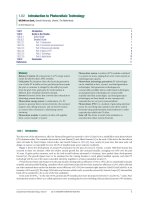
1.18.5 Device Properties
Current–Voltage (IV) analysis under standard conditions (AM1.5 illumination, 100 mW cm−2, 25 °C) represents the most com
monly applied device characterization. The IV curve can be described analytically or modeled numerically by 1D or
more-dimensional device simulation. The IV curve under illumination can be approximated by
� �
� �
qV−Rs JðVÞ
qV−Rs JðVÞ
JðVÞ ¼ J0 exp
−1 þ
−Jph ðVÞ
AkT
Rp
�
�
½4
Ea
J0 ¼ J00 exp −
AkT
where Jph(V) is the photocurrent density, k the Boltzmann constant, T the temperature, A diode quality factor, Rs the
series resistance, Rp the shunt resistance, Joo the dark current density prefactor, and Ea the barrier which limits recombination
in the dark. If the photocurrent collection does not depend on the voltage across the device, the superposition principle can be
applied and Jph can be simply subtracted from the dark current. Unfortunately for chalcopyrite thin-film devices, this is very often
not the case. The IV curve of a high-efficiency, 19.4%, solar cell is shown in Figure 16 yielding a Voc of 702 mV, Jsc = 35.6 mA cm−2,
and fill factor (FF) = 77.5%. This solar cell was deposited using a multistage co-evaporation process at 600 °C substrate
temperature [128]. The series resistance Rs = 0.3 Ω, shunt resistance Rp = 5 kΩ, and diode factor A = 1.4 were obtained from
the dark IV curve. Very often a cross-over between the dark IV and illuminated IV is observed, indicating that superposition
does not hold. The cross-over can be caused by internal barriers to photocollection that change under illumination and has
been related to a barrier at the CdS/CIGSe interface or to a heavily doped p+-layer in the CIGSe absorber close to the
heterointerface [198, 199].
External quantum efficiency curves for two Cu(In,Ga)Se2 solar cells are displayed together with the AM1.5 and AM0 norm
spectrum in Figure 17. The photocurrent obtained from an integration of the quantum efficiency multiplied by the AM1.5 spectrum
gives a value of 36.2 mA cm−2 for an effective band gap of 1.17 eV estimated from the steepest slope at long wavelengths. This is to be
compared to a possible photocurrent of 43 mA cm−2 that could be obtained if all photons incident on the solar cell could be
collected under short-circuit condition. The losses occurring are (1) reflection losses, (2) loss due to absorption in the ZnO layer, (3)
losses due to absorption in the CdS layer, and (4) losses due to recombination in the device. Reflection losses can be reduced by
application of suitable antireflection coating designed to minimize reflection of the complete layer stack. Absorption losses in the
ZnO layer can be reduced by optimization of the transmission of the ZnO layer, but here enough conductivity should be retained to
ensure lateral current collection at the maximum power point to keep the FF high. Absorption losses in the CdS layer can be
minimized by choice of a suitable buffer layer deposition and thickness and recombination losses can be reduced by minimizing the
recombination in the volume and at the heterointerface.
Chalcopyrite Thin-Film Materials and Solar Cells
20
35
16
30
Fraunhofer
25
Institut
Solare Energiesysteme
12
20
10
FF
Eta
5
0
0.492 cm2
35.6 mA cm−2
702.5 mV
77.5%
19.4%
Area
jsc
Voc
15
8
Power (mW cm−2)
Current density (mA cm−2)
40
415
4
0
0
100
200
300
400
500
600
700
Voltage (mV)
Figure 16 Current–voltage characteristic of 19.4% efficient glass/Mo/CuIn1−xGaxSe2/CdS/ZnO device. Figure from Haarstrich J, Metzner H, Oertel M,
et al. (2011) Increased homogeneity and open-circuit voltage of Cu(In,Ga)Se(2) solar cells due to higher deposition temperature. Solar Energy Materials
and Solar Cells 95(3): 1028–1030 [128].
Eg
CdS
External quantum efficiency (%)
6.1018
EgZnO
80
AMO
AM1,5
60
4.1018
40
2.1018
Photon flux (nm–1 cm–2 s–1)
EgCIGSe
100
20
0
500
1000
0
Wavelength (nm)
Figure 17 External quantum efficiency of two glass/Mo/CuIn1−xGaxSe2/CdS/ZnO devices, together with AM1.5 and AM0 norm spectrum.
(a)
–1
–2
(b)
(c)
Back contact
Energy (eV)
0
(d)
Buffer
Absorber
–3
0.0
0.2
0.4
Emitter
0.6
Distance (μm)
Figure 18 Band diagram for chalcopyrite-type heterojunction device indicating recombination processes: (a) back contact recombination; (b) bulk
recombination; (c) space-charge region recombination; (d) interface recombination.
In Figure 18, a band diagram for a chalcopyrite thin-film solar cell is shown. The main recombination processes that can occur in
such thin-film solar cells are recombination in the quasi-neutral region, recombination in the space-charge region, and recombina
tion at the CdS/CIGSe heterointerface. In general, it is of interest whether bulk recombination or interface recombination limits
416
Technology
20
1.2
0
Voc (V)
Photocurrent (mA cm–2)
1.0
10
0.8
0.6
0.4
0
−10
100
200
300
Temperature (K)
–20
0.0
0.2
0.4
0.6
0.8
1.0
Voltage (V)
Figure 19 Current–voltage–temperature measurement for glass/Mo/CuIn1−xGaxSe2/CdS/ZnO device. Inset shows the open-circuit voltage vs. temperature.
device performance, and in particular the open-circuit voltage Voc. The dominant recombination process limiting the device
efficiency can be deduced from temperature-dependent IV measurements, since the temperature dependence of the dark saturation
current and the diode-quality factor differ for different recombination processes [200]. The open circuit can be derived from the
diode equation given above for the condition that the photocurrent equals the dark current
�
�
�
�
J00
Ea AkT
kT Jph
−
ln
½5
Voc ¼
¼
q
q
Jph
q
J0
Therefore, a plot of the Voc versus temperature extracted temperature-dependent IV (IVT) measurements yields the activation energy of
the dark current. IVT measurements are shown in Figure 19. It can be seen the open-circuit voltage increases with lower temperature
and that at temperatures lower than 100 K a rollover occurs, which is due to photocurrent barriers. An extrapolation of the open-circuit
voltage to 0 K yields a value of 1.1 V, which is very close to the band gap value for this device, indicating that bulk recombination is the
limiting process for this device. If, in contrast, activation energy significantly smaller than the band gap value found, dominant
recombination at the heterointerface is indicated. In the general case, the values of the diode factor and saturation current have to be
carefully evaluated [201]. The fact that interface recombination does not seem to play a dominant role in optimized devices is
somewhat surprising, since this heterointerface in CIGSe/CdS solar cells is not lattice matched and should therefore contain a large
number of interface defects. The minor role of interface recombination may be explained by either a lowering of the VBM in the
absorber layer close to the heterointerface due to copper depletion at this interface or, due to type inversion in the same absorber
region, either due to heavy doping of the buffer/ZnO layer or due to Fermi-level pinning by shallow donors at the heterointerface.
In general, the value of the open-circuit voltage is found to be the parameter limiting high efficiencies in polycrystalline thin-film
devices [202]. The missing voltage with respect to the thermodynamic limit of approximately Eg – 0.3 V can be explained either by
residual nonradiative recombination or by the effect of potential or band gap fluctuations in the material. A strong correlation between
the open-circuit voltage and the minority carrier lifetime measured by photoluminescence decay has been observed [203, 204], with
highest values of more than 250 ns reported for high-efficiency devices [205]. Equivalent information about the recombination activity
can also be obtained from the photoluminescence yield, from which the quasi-Fermi level splitting in the absorber layer can be
deduced [51]. The quasi-Fermi level splitting poses an upper limit to the open-circuit voltage attainable from PV devices.
The open-circuit voltage is found to increase with increasing band gap of the device up to a certain band gap value in chalcopyrite
devices but saturates for band gaps larger than ∼1.3 eV [129, 202, 206]. This is shown in Figure 20 for a series of devices with
different Ga and S/Se content. Since both Ga and sulfur are found to raise the conduction band minimum (CBM), this could be
explained with an unfavorable band line-up at the heterointerface, that is, a cliff, thus preventing type inversion in the interface
region. However, a number of studies did not identify interface but rather bulk recombination as the limiting recombination
processes in wide band gap devices [12, 207]. It thus seems that for xGa > 0.3, the electronic quality of the absorber materials
deteriorates significantly with increasing Ga content, and an optimum is reached at band gap values around 1.2 eV.
Module fabrication of chalcopyrite solar cells can be monolithic if insulating substrates are used or by series connection of
individual cells. Both concepts are currently pursued by different thin-film companies. The monolithic interconnection works very
similar to the interconnection scheme in amorphous silicon or CdTe photovoltaic modules and is shown schematically in Figure 21.
The so-called P1 cut is scribed into the molybdenum after the back contact deposition. This can be easily performed by laser scribing
using nanosecond pulsed laser systems. After the deposition of the chalcopyrite absorber and buffer layer, the so-called P2 cut is made,
which is commonly scribed using a needle-based system, but can also now be performed by laser scribing either using picosecond or
Chalcopyrite Thin-Film Materials and Solar Cells
417
1.0
Radiative limit
Open circuit voltage (V)
0.9
CuGaSe2
0.8
CulnS2
CuInGaSe2
0.7
CulnSe2
0.6
0.5
0.4
0.8
1.0
1.2
1.4
Band gap (eV)
1.6
1.8
Figure 20 Open-circuit voltage vs. band gap for different chalcopyrite-type solar cells. The orange line indicates the open circuit voltage achievable only if
radiative recombination occurs in the device. Data from Contreras M, Mansfield LM, Egaas B, et al. presented at the 37th IEEE PVSEC, Seattle, USA, 2011
(unpublished); Unold T and Schock HW (2011) Nonconventional (non-silicon-based) photovoltaic materials. In: Clarke DR and Fratzl P (eds.) Annual Review
of Materials Research, vol. 41, pp. 297–321; and Schock HW, Rau U, Dullweber T, et al. presented at the EC PVSEC, Glasgow, Scottland, 2000 (unpublished).
Transparent front contact
Buffer layer
Absorber
Back contact
Substrate
Figure 21 Monolithic interconnect scheme for chalcopyrite-type thin-film modules.
using nanosecond laser systems [208]. After the deposition of the ZnO front contact layer, the final P3 cut is made, again usually by
needle scribing, but also possible using picosecond or nanosecond laser systems. The function of the P1 and P3 cuts is to isolate the
neighboring cells from each other, whereas the P2 cut enables the series connection between the neighboring cells by allowing a
contact between the doped ZnO of one cell with the Mo back contact of the neighboring cell. The interconnection geometry has to be
optimized to minimize losses of (1) series resistance losses in ZnO related to the cell width, (2) distance between P1 and P2, and (3)
distance between P2 and P3. After serial interconnection, the modules have to be protected against environmental influences, in
particular oxygen and moisture. This can be achieved by using a top glass pane that is laminated onto the active device using a polymer
such as EVA, as is used in crystalline silicon modules. Additional edge sealants may be required to keep moisture from entering the
module. The modules have to be certified by elaborate test procedures according to the international IEC protocols, which include the
so-called damp heat test (1000 h at 85 °C and 85% humidity) and additional electrical and mechanical stress and stability testing.
Significant light-induced degradation, as generally observed for amorphous silicon, is not generally found for chalcopyrite technology
but should be demonstrated for specific and in particular new device and module structures [15]. A possible implementation of an
inline manufacturing of chalcopyrite-based thin-film solar cells is shown in Figure 22.
1.18.6 Outlook
The fact that chalcopyrite materials can be deposited successfully by such a large variety of different process technologies proves
both an advantage and a disadvantage. The disadvantage is certainly that so far no critical mass of standardized deposition
equipment has evolved such that the capex could be lowered substantially in the manufacturing, without the need for scale up to
very large volumes. On the other hand, very simple low-cost techniques such as solution processing may generate a break-through
during the coming years, which could allow such substantial lowering of cost with regard to standard crystalline silicon technology.
418
Technology
Substrate
Mo-Back contact
P1 Cut
Absorber
Buffer layer
Encapsulation
P3 Cut
n-Doped ZnO
P2 Cut
Intrinsic ZnO
Figure 22 Schematic of inline manufacturing of chalcopyrite-type thin-film photovoltaic modules.
In this vein, the replacement of all vacuum equipment also for the back contact and front contact deposition could be an attractive
long-term vision.
At present, the major challenges for chalcopyrite-type solar cells involve the bridging of the gap between three-stage-process
deposited high-efficiency devices (>20%) and the efficiencies obtained with industrial technologies on module size, which can be
up to almost 18% for single sub-m2 modules. Currently, commercially sold Cu(In,Ga)Se2 modules are sold at total area efficiency of
12–13%. For a further increase, we believe that more processing and quality control has to be implemented, in particular to improve
the large- and small-scale homogeneities of these large area devices in the very fast industrial deposition processes applied. At the
same time, many questions with regard to the material science of the different functional layers, the processing of these layers, and in
particular the interplay between these different layers are open and need to be understood more properly.
Considering the renewable energy needs on a global scale during the next 40 years, one can foresee contributions of photovoltaic
electricity on the terawatt (TW) scale. This raises additional questions about the scarcity of elements used and the need for
environmentally friendly compounds and processes [202]. Here, the biggest problems for chalcopyrite materials are related to
the use of In, Ga, and Se, with In having received the largest attention because of its concurrent major use in consumer electronics.
There are different estimates with regard to natural reserves and availability of In [202]. It is, however, unquestionable that In is very
scarce in the Earth’s crust compared to other elements. Since In and Ga in Cu(In,Ga)Se2 materials can be replaced by the ordered
substitution of Zn and Sn yielding the quaternary or compound Cu2ZnSn(S,Se)4, (CZTS and CZTSe) considerable research has
recently focused on this polycrystalline semiconducting material. This material also shows a direct band gap of between 1 and 1.5 eV
depending on the S/Se content and is expected to possess very similar material properties to chalcopyrite compounds. Recently,
photoconversion efficiencies larger than 10% have been demonstrated [209], although there are many open questions with regard
to these absorber materials, device structure at the present. If the lessons learned and results achieved for chalcopyrite-based solar
cells can be transferred to this new material system, highly efficient thin-film photovoltaics based on earth-abundant materials
could present a strong option for a sustainable energy supply on the TW scale.
References
[1] Shay JL and Wernick JH (1975) Ternary Chalcopyrite Semiconductors: Growth, Electronic Properties and Applications. Oxford: Pergamon Press.
[2] Hahn H, Frank G, Klingler W, et al. (1953) Untersuchungen uber ternare chalkogenide.5. Uber einige ternare chalkogenide mit chalkopyritstruktur. Zeitschrift Fur Anorganische
Und Allgemeine Chemie 271(3–4): 153–170.
[3] Migliorato P, Tell B, Shay JL, and Kasper HM (1974) Junction electroluminescence in CuInSe2. Applied Physics Letters 24: 227.
[4] Wagner S, Shay JL, Migliorato P, and Kasper HM (1974) CuInSe2/CdS heterojunction photovoltaic detectors. Applied Physics Letters 25: 434.
[5] Shay J (1975) Efficient CuInSe2/CdS solar cells. Applied Physics Letters 27(2): 89.
[6] Kazmerski L (1976) Thin-film CuInSe2/CdS heterojunction solar cells. Applied Physics Letters 29(4): 268–270.
[7] Mickelsen RA and Chen WS, presented at the 15th IEEE Photovoltaic Specialists Conference, Orlando, 1981 (unpublished).
[8] Mickelsen RA and Chen WS, presented at the 16th IEEE Specialists Conference, New York, 1982 (unpublished).
[9] Jackson P, Hariskos D, Lotter E, et al. (2011) New world record efficiency for Cu(In,Ga)Se2 thin-film solar cells beyond 20%. Progress in Photovoltaics: Research and
Applications 19: 894–897.
[10] Sugimoto H, Yagioka T, Nagahashi M, et al. presented at the 37th IEEE Photovoltaic Specialists Confeence, Seattle, 2011 (unpublished).
[11] Rocket A and Birkmire RW (1991) CuInSe2 for photovoltaic applications. Journal of Applied Physics 70: R81.
[12] Shafarman W and Stolt L (2003) Cu(In,Ga)Se2 solar cells. In: Luque A and Hegedus S (eds.) Handbook of Photovoltaic Science and Engineering, pp. 567–616. West
Sussex: John Wiley & Sons. ISBN: 0-471-49196-9.
[13] Schock HW (2004) Properties of Chalcopyrite-based materials and film deposition for thin-film solar cells. In: Hamakawa Y (ed.) Thin-Film Solar Cells: Next Generation
Photovoltaics and Its Applications, pp. 163–182. Heidelberg, Germany: Springer-Verlag. ISBN: 3-540-43945.
[14] Singh UP and Patra SP (2010) Progress in polycrystalline thin-film Cu(In,Ga)Se2 solar cells. International Journal of Photoenergy 2010: 468147. doi:10.1155/2010/468147.
[15] Niki S, Contreras M, Repins I, et al. (2010) CIGS absorbers and processes. Progress in Photovoltaics: Research and Applications 18(6): 453–466.
[16] Scheer R and Schock HW (2011) Chalcogenide Photovoltaics: Physics, Technologies, and Thin Film Devices. Weinheim, Germany: Wiley-VCH.
Chalcopyrite Thin-Film Materials and Solar Cells
419
[17] Klenk R and Lux-Steiner MC (2006) Chalcopyrite based solar cells. In: Poortmans J and Arkhipov V (eds.) Thin FIlm Solar Cells: Fabrication, Characterization and Applications,
pp. 237–275. West Sussex, UK: John Wiley and Sons Ltd. ISBN: 0-470-09126-6. doi:10.1002/0470091282.ch6
[18] Grimm HG and Sommerfeld A (1978) Über den Zusammenhang des Abschlusses der Elektronengruppen im Atom mit den chemischen Valenzzahlen. Zeitschrift für
Physikalische Chemie 110: 17.
[19] Tomlins RD, Hill AE, and Pilkington RD (eds.) (1997) Ternary and multinary compounds. Proceedings of the 11th International Conference on Ternary and Multinary
Compounds, ICTMC-11, University of Salford, Institute of Physics Series Number 152, 8–12 September 1997. Bristol, UK; Philadelphia, PA: Institute of Physics Publishing.
[20] Herberholz R, Rau U, Schock HW, et al. (1999) Phase segregation, Cu migration and junction formation in Cu(In, Ga)Se-2. European Physical Journal-Applied Physics 6(2):
131–139.
[21] Suri DK, Nagpal KC, and Chadha GK (1989) X-RAY study of CuGaXIn1−XSe2 solid-solutions. Journal of Applied Crystallography 22: 578.
[22] Ishizuka S, Sakurai K, Yamada A, et al. (2005) Progress in the Efficiency of Wide-Gap Cu(In1-xGax)Se2 Solar Cells Using CIGSe Layers Grown in Water Vapor. Japanese Journal
of Applied Physics 44: L679–682.
[23] Abou-Ras D, Caballero R, Kaufmann CA, et al. (2008) Impact of the Ga concentration on the microstructure of CuIn1 −xGaxSe2. Physica Status Solidi-Rapid Research Letters
2(3): 135–137.
[24] Alonso MI, Wakita K, Pascual J, et al. (2001) Optical functions and electronic structure of CuInSe2, CuGaSe2, CuInS2, and CuGaS2. Physical Review B 63: 075203.
[25] Wei SH and Zunger A (1995) Band offsets and optical bowings of chalcopyrites And Zn-based II–VI alloys. Journal of Applied Physics 78(6): 3846–3856.
[26] Turcu M, Kotschau IM, and Rau U (2001) Band alignments in the Cu(In,Ga)(S,Se)(2) alloy system determined from deep-level defect energies. Applied Physics a-Materials
Science & Processing 73(6): 769–772.
[27] Maeda T and Wada T (2010) Electronic structue and characteristics of chemical bonds in CuInSe2, CuGaSe2 and CuAlSe2. Japanese Journal of Applied Physics 49: 04DP07.
[28] Palm J, Probst, V, and Karg FH (2004) Second generation CIS solar modules. Solar Energy 77(6): 757–765.
[29] Schmid D, Ruckh M, and Schock HW (1996) Photoemission studies on Cu(In,Ga)Se-2 thin films and related binary selenides. Applied Surface Science 103(4): 409–429.
[30] Noufi R, Axton R, Herrington C, and Deb S (1984) Electronic properties versus composition of thin films of CuInSe2. Applied Physics Letters 45: 668–670.
[31] Neumann H and Tomlinson RD (1990) Relation between electrical properties and composition in CuInSe2 single crystals. Solar Cells 28: 301–313.
[32] Dirnstorfer I, Wagner M, Hofmann DM, et al. (1998) Characterization of CuIn(Ga)Se2 Thin Films. Physica Status Solidi (a) 168: 163.
[33] Caballero R, Kaufmann CA, Eisenbarth T, et al. (2009) The effect of NaF precursors on low temperature growth of CIGS thin film solar cells on polyimide substrates. Physica
Status Solidi a – Applications and Materials Science 206(5): 1049–1053.
[34] Wei S (1999) Effects of Na on the electrical and structural properties of CuInSe2. Journal of Applied Physics 85(10): 7214.
[35] Niles DW, Al-Jassim M, and Ramanathan K (1999) Direct observation of Na and O impurities at grain surfaces of CuInSe2 thin films. Journal of Vacuum Science and
Technology A 17: 291–296.
[36] Kronik L, Cahen D, and Schock HW (1998) Effects of sodium on polycrystalline Cu(In,Ga)Se-2 and its solar cell performance. Advanced Materials 10(1): 31–36.
[37] Cojocaru-Mirédin O, Choi P, Wuerz R, and Raabe D (2011) Atomic-scale distribution of impurities in CuInSe2-based thin-film solar cells. Ultramicroscopy 111(6): 552–556.
[38] Caballero R, Kaufmann CA, Eisenbarth T, et al. (2009) The influence of Na on low temperature growth of CIGS thin film solar cells on polyimide substrates. Thin Solid Films 517(7):
2187–2190.
[39] Möller HJ (1993) Semiconductors for Solar Cells: Norwood, MA: Artech House Publishers.
[40] Zhang SB, Wei SH, Zunger A, and Katayama-Yoshida H (1998) Defect physics of the CuInSe2 chalcopyrite semiconductor. Physical Review B 57(16): 9642–9656.
[41] Wei SH, Zhang SB, and Zunger A (1998) Effects of Ga addition to CuInSe2 on its electronic, structural, and defect properties. Applied Physics Letters 72(24): 3199–3201.
[42] Zhao YJ, Persson C, Lany S, and Zunger A (2004) Why can CuInSe2 be readily equilibrium-doped n-type but the wider-gap CuGaSe2 cannot? Applied Physics Letters 85(24):
5860–5862.
[43] Walter T, Herberholz R, Muller C, and Schock HW (1996) Determination of defect distributions from admittance measurements and application to Cu(In,Ga)Se-2 based
heterojunctions. Journal of Applied Physics 80(8): 4411–4420.
[44] Heath J (2004) Bulk and metastable defects in CuIn1?xGaxSe2 thin films using drive-level capacitance profiling. Journal of Applied Physics 95(3): 1000.
[45] Heath J (2002) Effect of Ga content on defect states in CuIn1?xGaxSe2 photovoltaic devices. Applied Physics Letters 80(24): 4540.
[46] Eisenbarth T, Unold T, Caballero R, et al. (2010) Interpretation of admittance, capacitance-voltage, and current-voltage signatures in Cu(In,Ga)Se-2 thin film solar cells. Journal
of Applied Physics 107(3): 034509.
[47] Igalson M and Zabierowski P (1998) Laplace-DLTS of Cu(In,Ga)Se-2-based devices. In: Tomlinson RD, Hill AE, and Pilkington RD (eds.) Ternary and Multinary Compounds,
vol. 152, pp. 931–934.
[48] Wasim SM (1986). Transport properties of CuInSe2. Solar Cells 16: 289–316.
[49] Siebentritt S, Igalson M, Persson C, and Lany S (2010) The electronic structure of chalcopyrites-bands, point defects and grain boundaries. Progress in Photovoltaics 18(6):
390–410.
[50] Repins IL, Stanbery BJ, Young DL, et al. (2006) Comparison of device performance and measured transport parameters in widely-varying Cu(In,Ga) (Se,S) solar cells. Progress
in Photovoltaics: Research and Applications 14(1): 25–43.
[51] Unold T and Gutay L (2011) Photoluminescence of thin film solar cells. In: Abou-Ras D, Kirchatz T, Rau U (eds.) Advanced Characterization of Thin Film Solar
Cells, pp. 151–175. Weinheim, Germany: Wiley.
[52] Siebentritt S (2006) Shallow defects in the wide gap chalcopyrite CuGaSe2. In: Siebentritt S and Rau U (eds.) Wide-Gap Chalcopyrites, vol. 86, pp. 113–156. Heidelberg,
Germany: Springer-Verlag.
[53] Unold T, Enzenhofer T, Kaufmann CA, et al. (2006) Analysis of defects in coevaporated high-efficiency Cu(In,Ga)Se-2 solar cells. Photovoltaic Energy Conversion, Conference
Record of the 2006 IEEE 4th World Conference.Waikoloa, HI, May 2006.
[54] Rau U, Schmitt M, Parisi J, et al. (1998) Persistent photoconductivity in Cu(In,Ga)Se-2 heterojunctions and thin films prepared by sequential deposition. Applied Physics Letters
73(2): 223–225.
[55] Igalson M, Cwil M, and Edoff M (2007) Metastabilities in the electrical characteristics of CIGS devices: Experimental results vs theoretical predictions. Thin Solid Films
515(15): 6142–6146.
[56] Eisenbarth T, Nichterwitz M, Caballero R, et al. (2011) Characterization of metastabilities in Cu(In,Ga)Se[sub 2] thin-film solar cells by capacitance and current-voltage
spectroscopy. Journal of Applied Physics 110: 094506–094513.
[57] Ruberto MN and Rothwarf A (1987) Time-dependent open-circuit voltage in CuInSe2 solar cells: Theory and experiment. Journal of Applied Physics 61: 4662.
[58] Mack P, Walter T, Hariskos D, et al. presented at the 24th European Photovoltaic Solar Energy Conference, Hamburg, 2009 (unpublished).
[59] Cwil M, Igalson M, Zabierowski P, and Siebentritt S (2008) Charge and doping distributions by capacitance profiling in Cu(In, Ga)Se-2 solar cells. Journal of Applied Physics
103(6): 063701.
[60] Engelhardt F, Schmidt M, Meyer T, et al. (1998) Metastable electrical transport in Cu(In,Ga)Se-2 thin films and ZnO/CdS/Cu(In,Ga) Se-2 heterostructures. Physics Letters A
245(5): 489–493.
[61] Eisgruber IL, Granata JE, Sites JR, et al. (1998) Blue-photon modification of nonstandard diode barrier in CuInSe2 solar cells. Solar Energy Materials and Solar Cells 53: 367.
[62] Igalson M, Bodegard M, and Stolt L (2003) Reversible changes of the fill factor in the ZnO/CdS/Cu(In,Ga)Se-2 solar cells. Solar Energy Materials and Solar Cells 80(2):
195–207.
[63] Lany S and Zunger A (2006) Light- and bias-induced metastabilities in Cu(In,Ga)Se-2 based solar cells caused by the (V-Se-V-Cu) vacancy complex. Journal of Applied
Physics 100(11): 113725.
420
Technology
[64] Nishitani M, Negami T, Kohara N, and Wada T (1997) Analysis of transient photocurrents in Cu(In,Ga)Se2 thin film solar cells. Journal of Applied Physics 82: 3572.
[65] Meyer T, Engelhardt F, Parisi, J, and Rau U (2002) Spectral dependence and Hall effect of persistent photoconductivity in polycrystalline Cu(In,Ga)Se-2 thin films. Journal of
Applied Physics 91(8): 5093–5099.
[66] Dinca SA, Schiff EA, Egaas B, et al. (2009) Hole drift mobility measurements in polycrystalline CuInGaSe2. Physical Review B 80: 235201.
[67] Rau U, Taretto K, and Siebentritt S (2009) Grain boundaries in Cu(In, Ga)(Se, S)(2) thin-film solar cells. Applied Physics A – Materials Science & Processing 96(1): 221–234.
[68] Abou-Ras D, Schorr S, and Schock HW (2007) Grain-size distributions and grain boundaries of chalcopyrite-type thin films. Journal of Applied Crystallography 40: 841–848.
[69] Seto J (1975) The electrical properties of polycrystalline silicon films. Journal of Applied Physics 46(12): 5247.
[70] Visoly-Fisher I, Cohen SR, Ruzin A, and Cahen D (2004) How polycrystalline devices can outperform single-crystal ones: THin film CdTe/CdS solar cells. Advanced Materials
16: 879.
[71] Azulay D, Millo O, Balberg I, et al. (2007) Current routes in polycrystalline CuInSe2 and Cu(In,Ga)Se-2 films. Solar Energy Materials and Solar Cells 91(1): 85–90.
[72] Gloeckler M (2005) Grain-boundary recombination in Cu(In,Ga)Se2 solar cells. Journal of Applied Physics 98(11): 113704.
[73] Taretto K and Rau U (2008) Numerical simulation of carrier collection and recombination at grain boundaries in Cu(In,Ga)Se-2 solar cells. Journal of Applied Physics 103(9):
094523.
[74] Persson C and Zunger A (2003) Anomalous grain boundary physics in polycrystalline CuInSe2: The existence of a hole barrier. Physical Review Letters 91(26):
266401.
[75] Lei C (2010) Effects of solution-grown CdS on Cu(InGa)Se2 grain boundaries. Journal of Applied Physics 108(11): 114908.
[76] Abou-Ras D, Schaffer B, Schaffer M, et al. (in press) Direct insight into grain boundary reconstruction in polycrystalline Cu(In,Ga)Se 2 with atomic resolution. Physical Review
Letters.
[77] Sadewasser S, Abou-Ras D, Azulay D, et al. (2011) Nanometer-scale electronic and microstructural properties of grain boundaries in Cu(In,Ga)Se(2). Thin Solid Films 519(21):
7341–7346.
[78] Abou-Ras D, Jahn U, Nichterwitz M, et al. (2010) Combined electron backscatter diffraction and cathodoluminescence measurements on CuInS2/Mo/glass stacks and CuInS2
thin-film solar cells. Journal of Applied Physics 107(1): 014311.
[79] Nichterwitz M, Abou-Ras D, Sakurai K, et al. (2009) Influence of grain boundaries on current collection in Cu(In,Ga)Se-2 thin-film solar cells. Thin Solid Films 517(7):
2554–2557.
[80] Kazmerski LL, Ayyagari MS, White FR, and Sanborn GA (1976) Growth and properties of vacuum-deposited culnse2 thin-films. Journal of Vacuum Science & Technology 13(1):
139–144.
[81] Gogol CA and Reagan SH (1983) A performance comparison of vacuum deposition monitors employing atomic absorption (AA) and electron impact emission spectroscoopy
(EIES). Journal of Vacuum Science & Technology A 1: 252–256.
[82] Shafarman WN and Zhu J (2000) Effect of substrate temperature and depostion profile on evaporated Cu(InGa)Se2 films and devices. Thin Solid Films 361–362: 473–477.
[83] Mickelsen RA and Chen WS (1980) High photocurrent polycrystalline thin-film CdS/CuInSe2 solar cella. Applied Physics Letters 36: 371–373.
[84] Repins I, Contreras M, Egaas B, et al. (2008) 19.9%-efficient ZnO/CdS/CuInGaSe2 Solar Cell with 81.2% Fill Factor. Progress in Photovoltaics: Research and Applications 16:
235–239.
[85] Gabor A (1994) High-efficiency CuInxGa1-xSe2 solar cells made from (Inx,Ga1-x)2Se3 precursor films. Applied Physics Letters 65(2): 198.
[86] Gabor AM, Tuttle JR, Bode MH, et al. (1996) Band-gap engineering in Cu(In,Ga) Se2 thin films grown from (In,Ga)2Se3 precursors. Solar Energy Materials and Solar Cells
41–42: 247–260.
[87] Caballero R, Kaufmann CA, Efimova V, et al. (2012) Investigation of Cu(In,Ga)Se2 thin-film formation during the multi-stage co-evaporation process. Progress in Photovoltaics
Research and Applications. doi: 10.1002/pip.1233.
[88] Kessler F, Schmid D, Zweigart S, et al. (1994) CuInSe2 formation from sequential deposition of In(Se):Cu:Se, pp. 684–652. Proceedings of the 12th EU PVSEC. Amsterdam,
1994.
[89] Klenk R, Walter T, Schock HW, and Cahen D (1993) A model for the successful growth of polycrystalline films of cuinse2 by multisource physical vacuum evaporation.
Advanced Materials 5(2): 114–119.
[90] Wada T, Kohara N, Negami T, and Nishitani M (1997) Growth of CuInSe2 crystals in Cu-rich Cu-In-Se thin films. Journal of Materials Research 12: 1456–1462.
[91] Kessler J, Chityuttakan C, Lu J, et al. (2003) Cu(In,Ga)Se2 thin films grown with a Cu-poor/rich/poor sequence: Growth model and structural considerations. Progress in
Photovoltaics: Research and Applications 11(5): 319–331.
[92] Barreau N, Painchaud T, Couzinié-Devy F, et al. (2010) Recrystallization of CIGSe layers grown by three-step processes: A model based on grain boundary migration. Acta
Materialia 58(17): 5572–5577.
[93] Rodriguez-Alvarez H, Mainz R, Marsen B, et al. (2010) Recrystallization of Cu-In-S thin films studied in situ by energy-dispersive X-ray diffraction. Journal of Applied
Crystallography 43: 1053–1061.
[94] Sakurai K, Hunger R, Scheer R, et al. (2004) In situ diagnostic methods for thin-film fabrication: Utilization of heat radiation and light scattering. Progress in Photovoltaics
12(2–3): 219–234.
[95] Hesse R, Caballero R, Abou-Ras D, et al. (2007) A reliable optical method for in-situ process control for deposition of Cu(In,Ga)Se2 thin layers for photovoltaics – Art. no.
665108. In: VonRoedern B and Delahoy AE (eds.) Photovoltaic Cell and Module Technologies, vol. 6651, pp. 65108–65108.
[96] Repins I, Gomez N, Simpson L, and Joshi B (2005) In situ sensors for CIGS deposition and manufacture. Materials Research Society Symposia Proceedings 865: 499–510.
Materials Research Society.
[97] Kessler F, Scholdstrom J, and Stolt L, presented at the 28th IEEE PVSEC, Anchorage, USA, 2000 (unpublished).
[98] Kaigawa R, Wada T, Bakehe S, and Klenk R (2006) Three-stage evaporation of Cu(In,Ga)S2 solar cell absorber films without KCN treatment and Na control. Thin Solid Films
511–512: 430–433.
[99] Merdes S, Mainz R, Klaer J, et al. (2011) 12.6% efficient CdS/Cu(In,Ga)S(2)-based solar cell with an open circuit voltage of 879 mV prepared by a rapid thermal process. Solar
Energy Materials and Solar Cells 95(3): 864–869.
[100] Stolt L, Hedstrom J, Kessler J, et al. (1993) Zno/Cds/Cuinse2 thin-film solar-cells with improved performance. Applied Physics Letters 62(6): 597–599.
[101] Dimmler B and Schock HW (1996) Scaling-up of CIS technology for thin-film solar modules. Progress in Photovoltaics 4(6): 425–433.
[102] Jackson P, Wurz R, Rau U, et al. (2007) High quality baseline for high efficiency, Cu(In1 −x,Gax)Se2 solar cells. Progress in Photovoltaics 15(6): 507–519.
[103] Hibberd CJ, Chassaing E, Liu W, et al. (2010) Non-vacuum methods for formation of Cu(In,Ga)(Se,S)(2) thin film photovoltaic absorbers. Progress in Photovoltaics 18(6):
434–452.
[104] Hergert F, Jost S, Hock R, and Purwins M (2006) A crystallographic description of experimentally identified formation reactions of Cu(In,Ga)Se2. Journal of Solid State
Chemistry 179(8): 2394–2415.
[105] Djordjevic J, Rudigier E, and Scheer R (2006) Real-time studies of phase transformations in Cu-In-Se-S thin films – 3: Selenization of Cu-In precursors. Journal of Crystal
Growth 294(2): 218–230.
[106] Roussel O, Ramdani O, Chassaing E, et al. (2008) First stages of CuInSe2 electrodeposition from Cu(II)-In(III)-Se(IV) acidic solutions on polycrystalline mo films. Journal of the
Electrochemical Society 155(2): D141–D147.
[107] Marudachalam M, Hichri H, Klenk R, et al. (1995) Preparation of homogeneous Cu(In,Ga)Se2 films by selenization of metal precursors in H2S atmosphere. Applied Physics
Letters 67: 3978.
[108] Basol B and Kapur VK (1990) Deposition of CuInSe2 films by a two-stage process utilizing E-beam evaporation. IEEE Transactions on Electron Devices 37: 418–421.
Chalcopyrite Thin-Film Materials and Solar Cells
421
[109] Caballero R and Guillén C (2002) Comparative studies between Cu_Ga_Se and Cu_In_Se thin film systems. Thin Solid Films 403–404: 107–111.
[110] Kapur VK, Basol B, and Tseng E (1987) Low cost methods for the production of semiconductor films for CuInSe2/CdS solar cells. Solar Cells 21: 65–70.
[111] Guillemoles JF, Cowache P, Lusson A, et al. (1996) One, step electrodeposition of CuInSe2: Improved structural, electronic, and photovoltaic properties by annealing under high
selenium pressure. Journal of Applied Physics 79(9): 7293–7302.
[112] Kapur VK, Bansal A, Le P, and Asensio OI (2003) Non-vacuum processing of CuIn1 −xGaxSe2 solar cells on rigid and flexible substrates using nanoparticle precursor inks. Thin
Solid Films 431–432: 53–57.
[113] Guo Q, Ford GM, Hillhouse HW, and Agrawal R (2009) Sulfide nanocrystal inks for dense Cu(In(1−x)Ga(x))(S(1-y)Se(y))2 absorber films and their photovoltaic performance.
Nano Letters 9: 3060.
[114] Mitzi DB, Yuan M, Liu W, et al. (2009) Hydrazine-based deposition route for device-quality CIGS films. Thin Solid Films 517(7): 2158–2162.
[115] Taunier S, Sicx-Kurdi J, Grand PP, et al. (2005) Cu(In,Ga)(S,Se)(2) solar cells and modules by electrodeposition. Thin Solid Films 480: 526–531.
[116] Basol BM, Pinarbasi M, Aksu S, et al. presented at the IEEE Photovoltaic Specialists Conference, 2009 (unpublished).
[117] Grindle S, Smith C, and Mittleman S (1979) Preparation and properties of CuInS2 thin films produced by exposing sputtered Cu-In films to an H2S atmosphere. Applied Physics
Letters 35: 24–26.
[118] Chu T, Chu S, Lin S, and Yue J (1984) Large Grain Copper Indium Diselenide Films. Journal of the Electrochemical Society 131: 2182–2185.
[119] Mooney GD, Hermann AM, Tuttle JR, et al. (1991) Formation of CuInSe2 thin films by rapid thermal recrystallization. Applied Physics Letters 58: 678–2680.
[120] Siemer K, Klaer J, Luck I, et al. (2001) Efficient CuInS2 solar cells from a rapid thermal process (RTP). Solar Energy Materials and Solar Cells 67(1–4): 159–166.
[121] Kulkarni SS, Koishiyev GT, Moutinho H, and Dhere NG (2009) Preparation and characterization of CuIn1−xGaxSe2 −ySy thin film solar cells by rapid thermal processing. Thin
Solid Films 517(7): 2121–2124.
[122] Hergert F, Hock R, Weber A, et al. (2005) In situ investigation of the formation of Cu(In,Ga)Se2 from selenised metallic precursors by X-ray diffraction – The impact of gallium
sodium and selenium excess. Journal of Physics and Chemistry of Solids 66: 1903–1907.
[123] Rodriguez-Alvarez H, Kotschau IM, and Schock HW (2008) Pressure-dependent real-time investigations on the rapid thermal sulfurization of Cu-In thin films. Journal of Crystal
Growth 310(15): 3638–3644.
[124] Mainz R (2011) In situ analysis of elemental depth distributions in thin films by combined evaluation of synchrotron x-ray fluorescence and diffraction. Journal of Applied
Physics 109(12): 123515.
[125] Weber A, Rodriguez-Alvarez H, Mainz R, et al. presented at the IEEE Photovoltaic Specialists Conference, Seattle, 2011 (unpublished).
[126] Kaufmann CA, Caballero R, Unold T, et al. (2009) Depth profiling of Cu(In,Ga)Se2 thin films grown at low temperatures. Solar Energy Materials and Solar Cells 93(6–7):
859–863.
[127] Chirila A, Blösch P, Pianezzi F, et al. presented at the 26th EU PVSEC, Hamburg, 2011 (unpublished).
[128] Haarstrich J, Metzner H, Oertel M, et al. (2011) Increased homogeneity and open-circuit voltage of Cu(In,Ga)Se(2) solar cells due to higher deposition temperature. Solar Energy
Materials and Solar Cells 95(3): 1028–1030.
[129] Contreras M, Mansfield LM, Egaas B, et al. presented at the 37th IEEE PVSEC, Seattle, USA, 2011 (unpublished).
[130] Nakada T and Shirakata S (2011) Impacts of pulsed-laser assisted deposition on CIGS thin films and solar cells. Solar Energy Materials and Solar Cells 95(6): 1463–1470.
[131] Li Z, Nishijima M, Yamada A, and Konagai M (2009) Growth of Cu(In,Ga)Se2 thin films using ionization Ga source and application for solar cells. Physica Status Solidi (c) 5:
1273–1277.
[132] Caballero R, Izquierdo-Roca V, Fontane X, et al. (2010) Cu deficiency in multi-stage co-evaporated Cu(In,Ga)Se2 for solar cells applications: Microstructure and Ga in-depth
alloying. Acta Materialia 58(9): 3468–3476.
[133] Rissom T, Kaufmann CA, Caballero R, et al. (2012) Influence of the Se rate on high-temperature deposited CIGSe thin film solar cells. Thin Solid Films.
[134] Chaisitsak S, Yamada A, and Konagai M (2002) Preferred Orientation Control of Cu(In1−xGax)Se2 (x ≈ 0.28) Thin Films and Its Influence on Solar Cell Characteristics. Japanese
Journal of Applied Physics 41: 507–513.
[135] Contreras M, Repins I, Metzger WB, et al. (2009) Se activity and its effect on Cu(In,Ga)Se2 photovoltaic thin films. Physica Status Solidi A – Applications and Materials Science
5: 1042–1048.
[136] Ishizuka S, Shibata H, Yamada A, et al. (2007) Growth of polycrystalline Cu(In,Ga)Se2 thin films using a radio frequency-cracked Se-radical beam source and application for
photovoltaic devices. Applied Physics Letters 91: 041902.
[137] Puttnins S, Zachmann H, Rahm A, et al. presented at the 25th EU PVSEC, Valencia, Spain, 2010 (unpublished).
[138] Güttler D, Chirila A, Seyrling S, et al. presented at the Honolulu, USA, 2010 (unpublished).
[139] Rudmann D, Bremaud D, Dacunha A, et al. (2005) Sodium incorporation strategies for CIGS growth at different temperatures. Thin Solid Films 480-481: 55-60. doi: 10.1016/j.
tsf.2004.11.071.
[140] Caballero R, Kaufmann CA, Eisenbarth T, et al. (2011) High efficiency low temperature grown Cu(In,Ga)Se(2) thin film solar cells on flexible substrates using NaF precursor
layers. Progress in Photovoltaics 19(5): 547–551.
[141] Caballero R, Kaufmann CA, Eisenbarth T, et al. (2010) Influence of Na on Cu(In,Ga)Se-2 solar cells grown on polyimide substrates at low temperature: Impact on the Cu(In,Ga)
Se-2/Mo interface. Applied Physics Letters 96(9): 092104.
[142] Ishizuka S, Yamada A, Fons P, and Niki S (2008) Flexible Cu(In,Ga)Se2 solar cells fabricated using alkali-silicate glass thin layers as an alkjali source material. Journal of
Renewable and Sustainable Energy 1: 013102.
[143] Yun J, Kim K, Kim M, et al. (2007) Fabrication of CIGS solar cells with a Na-doped Molayer on a Na-free substrate. Thin Solid Films 515(15): 5876–5879.
[144] Rockett A (2005) The effect of Na in polycrystalline and epitaxial single-crystal CuIn1−xGaxSe2. Thin Solid Films 480: 2–7.
[145] Seward TP and Vascott T (eds.) (2005) High Temperature Glass Melt Property Database for Process Modeling. Westerville, OH: The American Ceramic Society.
[146] Rau U and Schock HW (1999) Electronic properties of Cu(In,Ga)Se-2 heterojunction solar cells-recent achievements, current understanding, and future challenges. Applied
Physics A – Materials Science & Processing 69(2): 131–147.
[147] Hedstrom J, Ohlsen H, Bodegard M, et al. (1993) Zno/Cds/Cu(IN,GA)Se2 thin-film solar-cells with improved performance, pp. 364–371. Conference Record of the Twenty Third
IEEE Photovoltaic Specialists Conference. May 1993.
[148] Herz K, Kessler F, Wächter R, et al. (2002) Dielectric barriers for flexible CIGS solar modules. Thin Solid Films 403–404: 384–389.
[149] DuPont Electronic Technologies (2011) Product information, Kapton 100 HN Film, 25μm. />[150] Heraeus-Quarzglas GmbH & Co. KG (2011) Product information. />QuartzBaseMaterials_semifinishedfusedsilica~1.pdf.
[151] Duran Group GmbH (2011) Product information. />[152] Wuerz R, Eicke A, Kessler F, et al. (2011) Alternative sodium sources for Cu(In,Ga)Se2 thin-film solar cells on flexible substrates. Thin Solid Films 519(21): 7268–7271.
[153] Kessler F and Rudmann D (2004) Technological aspects of flexible CIGS solar cells and modules. Solar Energy 77(6): 685–695.
[154] Eisenbarth T, Caballero R, Kaufmann CA, et al. (in press) Impact of iron on defect concentrations and device performance for CuIn(1−x)GaxSe2. Solar Cells on Stainless Steel.
[155] Contreras M, Egaas B, Ramanathan K, et al. (1999) Progress toward 20% efficiency in Cu(In,Ga)Se2 polycrystalline thin-film solar cells. Progress in Photovoltaics 7: 311–316.
[156] Wuerz R, Eicke A, Frankenfeld M, et al. (2009) CIGS thin-film solar cells on steel substrates. Thin Solid Films 517(7): 2415–2418.
[157] Yagioka T and Nakada T (2009) Cd-free flexible Cu(In,Ga)Se2 thin film solar cells with ZnS(O,OH) buffer layers on Ti foils. Applied Physics Express 2: 072201.
[158] Kaufmann CA, Neisser A, Klenk R, and Scheer R (2005) Transfer of Cu(In,Ga)Se-2 thin film solar cells to flexible substrates using an in situ process control. Thin Solid Films
480: 515–519.
422
Technology
[159] Brémaud D, Rudmann D, Kaelin M, et al. (2007) Flexible Cu(In,Ga)Se2 on Al foils and the effects of Al during chemical bath deposition. Thin Solid Films 515(15):
5857–5861.
[160] Rechid J, Thyen R, Raitzig A, et al. presented at the 3rd World Conference on Photovoltaic Energy Conversion, Osaka, Japan, 2003 (unpublished).
[161] Nakada T, Kuraishi T, Inoue T, and Mise T, presented at the 35th IEEE PVSEC, Honolulu, USA, 2010 (unpublished).
[162] Chiril˘a A, Buecheler S, Pianezzi F, et al. (2011) Highly efficient Cu(In,Ga)Se2 solar cells grown on flexible polymer films. Nature Materials 10(11): 857–861.
[163] Kessler F, Herrmann D, and Powalla M (2005) Approaches to flexible CIGS thin-film solar cells. Thin Solid Films 480–481: 491–498.
[164] Stolwijk NA (2010) Fe diffusion in polycrystalline Cu(In,Ga)Se2 layers for thin-film solar cells. Applied Physics Letters 96(24): 244101.
[165] Kamikawa-Shimizu Y, Shimada S, Watanabe M, et al. (2009) Effects of Mo back contact thickness on the properties of CIGS solar cells. Physica Status Solidi A – Applications
and Materials Science 206: 1063–1066.
[166] Scofield JH, Duda A, Albin D, et al. (1995) Sputtered molybdenum bilayer back contact for copper indium diselenide-based poylcrystalline thin-film solar cells. Thin Solid Films
260: 26–31.
[167] Al-Thani HA, Hasoon FS, Young M, et al. presented at the 29th IEEE Photovoltaic Specialists Conference, New Orleans, 2002 (unpublished).
[168] Shafarman W and Phillips JE (1996) Direct current-voltage measurements of the Mo/CuInSe2 contact on operating solar cells. Proceedings of the 25th IEEE PV Specialists
Conference: Washington, USA, 13–17 May 1996, 917–919.
[169] Kohara N, Nishiwaki S, Hashimoto Y, et al. (2001) Electrical properties of the Cu(In,Ga)Se2/MoSe2/Mo structure. Solar Energy Materials and Solar Cells 67: 209–215.
[170] Russell PE, Jamjoum O, Ahrenkiel RK, and Kazmerski LL (1982) Properties of the Mo-Culnse2 interface. Applied Physics Letters 40(11): 995–997.
[171] Jaegermann W, Löher T, and Pettenkofer C (1996) Surface properties of chalcopyrite semiconductors. Crystal Research and Crystal Technology 31: 273.
[172] Orgassa K, Schock HW, and Werner JH (2003) Alternative back contact materials for thin film Cu(In,Ga)Se-2 solar cells. Thin Solid Films 431: 387–391.
[173] Shafarman WN and Stolt L (2003) Cu(InGa)Se2 solar cells. In: Luque A and Hegedus S (eds.) Handbook of Photovoltaic Science and Engineering, p. 567. West Sussex: John Wiley.
[174] Rietke PC and Bentjen S (1993) Deposition of cadmium sulfide films by decomposition of thiourea in basic solution. Chemistry of Materials 5: 4–53.
[175] Lehmann JI (2010) Oberflächenpräparation zur Untersuchung von elektronischen Korngrenzeneigenschaften in Cu(In,Ga)Se2. Diploma Thesis, Freie Universitat Berlin.
[176] Allsop N, Kauffmann CA, Neisser A, et al. presented at the Mater. Res. Soc. Symp.Proc., San Francisco, 2005 (unpublished).
[177] Buffière M, Harel S, Arzel L, et al. (2011) Fast chemical bath deposition of Zn(O,S) buffer layers for Cu(In,Ga)Se2 solar cells. Thin Solid Films 519(21): 7575–7578.
[178] Contreras MA, Nakada T, Hongo M, et al. presented at the 3rd WCPEC, Osaka, Japan, 2003 (unpublished).
[179] Couzinié-Devy F, Barreau N, and Kessler J (2009) Influence of absorber copper concentration on the Cu(In,Ga)Se2/(PVD)In2S3 and Cu(In,Ga)Se2/(CBD)CdS based solar cells
performance. Thin Solid Films 517(7): 2407–2410.
[180] Engelhardt F, Bornemann L, Kontges M, et al. (1999) Cu(In,Ga)Se-2 solar cells with a ZnSe buffer layer: Interface characterization by quantum efficiency measurements.
Progress in Photovoltaics 7(6): 423–436.
[181] Ernits K, Brémaud D, Buecheler S, et al. (2007) Characterisation of ultrasonically sprayed InxSy buffer layers for Cu(In,Ga)Se2 solar cells. Thin Solid Films 515(15): 6051–6054.
[182] Fischer C-H, Allsop NA, Gledhill SE, et al. (2011) The spray-ILGAR® (ion layer gas reaction) method for the deposition of thin semiconductor layers: Process and applications
for thin film solar cells. Solar Energy Materials and Solar Cells 95(6): 1518–1526.
[183] Huang CH, Li SS, Shafarman WN, et al. (2001) Study of Cd-free buffer layers using Inx(OH,S)y on CIGS solar cells. Solar Energy Materials and Solar Cells 69(2): 131–137.
[184] Hariskos D, Menner R, Jackson P, et al. presented at the 26th EUPVSEC, Hamburg, Germany, 2011 (unpublished).
[185] Okamoto A, Minemoto T, and Takakura H (2011) Application of sputtered ZnO1-xSx buffer layers for Cu(In,Ga)Se2 solar cells. Japanese Journal of Applied Physics 50: 04DP10.
[186] Pistor P, Caballero R, Hariskos D, et al. (2009) Quality and stability of compound indium sulphide as source material for buffer layers in Cu(In,Ga)Se solar cells. Solar Energy
Materials and Solar Cells 93(1): 148–152.
[187] Sáez-Araoz R, Ennaoui A, Kropp T, et al. (2008) Use of different Zn precursors for the deposition of Zn(S,O) buffer layers by chemical bath for chalcopyrite based Cd-free
thin-film solar cells. Physica Status Solidi (a) 205(10): 2330–2334.
[188] Siebentritt S, Walk P, Fiedeler U, et al. (2004) MOCVD as a dry deposition method of ZnSe buffers for Cu(In,Ga)(S,Se)2 solar cells. Progress in Photovoltaics: Research and
Applications 12(5): 333–338.
[189] Yakioka T and Nakada T (2009) Cd-Free Flexible CI8In,Ga)Se2 Thin Film solar Cells with ZnS(O,OH) Buffer Layers on Ti Foils. Applied Physics Express 2: 072201.
[190] Hariskos D, Spiering S, and Powalla M (2005) Buffer layers in Cu(In,Ga)Se2 solar cells and modules. Thin Solid Films 480–481: 99.
[191] Siebentritt S (2004) Alternative buffers for chalcopyrite solar cells. Solar Energy 77(6): 767–775.
[192] Naghavi N, Abou-Ras D, Allsop N, et al. (2010) Buffer layers and transparent conducting oxides for chalcopyrite Cu(In,Ga)(S,Se)(2) based thin film photovoltaics: Present status
and current developments. Progress in Photovoltaics 18(6): 411–433.
[193] Orgassa K, Rau U, Nguyen Q, et al. (2002) Role of the CdS buffer layer as an active optical element in Cu(In,Ga)Se-2 thin-film solar cells. Progress in Photovoltaics 10(7):
457–463.
[194] Pettersson J, Platzer-Bjorkman C, and Edoff M (2009) Temperature-dependent current-voltage and light-soaking measurements on Cu(In,Ga)Se2 solar cells with ALDZn1-xMgx buffer layers. Progress in Photovoltaics: Research and Applications 17: 460–469.
[195] Ishizuka S, Sakurai K, Yamada A, et al. (2005) Fabrication of wide-gap Cu(In1 −xGax)Se2 thin film solar cells: A study on the correlation of cell performance with highly resistive
i-ZnO layer thickness. Solar Energy Materials and Solar Cells 87: 541–548
[196] Olsen LC, Eschbach P, and Kundu S (2002) Role of buffer layers in CIS based solar cells, p. 652. Proceedings of the 29th IEEE Photovoltaic Specialists Conference. New
Orleans, LA, 2002.
[197] Minemoto T (2001) Cu(In,Ga)Se2 solar cells with controlled conduction band offset of window/Cu(In,Ga)Se2 layers. Journal of Applied Physics 89(12): 8327.
[198] Niemegeers A, Burgelman M, Herberholz R, et al. (1998) Model for electronic transport in Cu(In,Ga)Se-2 solar cells. Progress in Photovoltaics 6(6): 407–421.
[199] Gloeckler M, Jenkins CR, and Sites JR, presented at the Mat. Res. Soc. Sympos., 2003 (unpublished).
[200] Fahrenbruch A and Bube RH (1983) Fundamentals of Solar Cells: Photovoltaic Energy Conversion. New York: Academic Press.
[201] Scheer R (2009) Activation energy of heterojunction diode currents in the limit of interface recombination. Journal of Applied Physics 105(10): 104505.
[202] Unold T and Schock HW (2011) Nonconventional (non-silicon-based) photovoltaic materials. In: Clarke DR and Fratzl P (eds.) Annual Review of Materials Research, vol. 41, pp.
297–321.
[203] Ohnesorge B (1998) Minority-carrier lifetime and efficiency of Cu(In,Ga)Se2 solar cells. Applied Physics Letters 73(9): 1224.
[204] Repins IL, Metzger WK, Perkins CL, et al. (2009) Measured Minority-Carrier Lifetime And CIGS Device Performance. Proceedings of the 34th IEEE Photovoltaic Specialists
Conference, p. 978.
[205] Metzger WK (2008) Long lifetimes in high-efficiency Cu(In,Ga)Se2 solar cells. Applied Physics Letters 93(2). 022110.
[206] Schock HW, Rau U, Dullweber T, et al. presented at the EC PVSEC, Glasgow, Scottland, 2000 (unpublished).
[207] Turcu M, Pakma O, and Rau U (2002) Interdependence of absorber composition and recombination mechanism in Cu(In,Ga)(Se,S)(2) heterojunction solar cells. Applied
Physics Letters 80(14): 2598–2600.
[208] Schultz C, Schüle M, Richter M, et al. presented at the 26th European Photovoltaic Solar Energy Conference, Hamburg, 2011 (unpublished).
[209] Barkhouse DAR, Gunawan O, Gokmen T, et al. (2011) Device Characteristics of a 10.1% Hydrazine-Processed Cu2ZnSn(Se,S)4 Solar Cell Progress in Photovoltaics: Research
and Applications. Chichester, UK: Wiley.