Photovoltaic (Solar Cells) - pin mat troi
Bạn đang xem bản rút gọn của tài liệu. Xem và tải ngay bản đầy đủ của tài liệu tại đây (4.06 MB, 50 trang )
Ø
II
Chap 4 : Photovoltaic (Solar Cells)
O00
onoonoo00
@
Introduction
I
The history of photovoltaics goes back to the year 1839,
when Becquere discovered the photovoltaic effect, but no
technology was available in the 19t century to exploit this
discovery. The semiconductor age only began about 100
years later. After Shockley had developed a model for the
pn junction, Bell Laboratories produced the first solar cell
in 1954; the efficiency of this, in converting light into
electricity, was about 5%.
Photovoltaics offers the highest versatility among
renewable energy technologies.
Theoretically, PV systems could cover the whole
electricity demand of most countries in the world.
i
CĐ
rm
2/70
@
Tntroduction
I
Worldwide, the installed photovoltaics capacity and the
share of electricity generated by PV are still low, despite
impressive market growth. The political environment and
magnitude of market introduction programmes will
determine the future of this technology.
3/70
@
The photo effect
Light, with its photon energy, can provide the energy to lift
an electron to a higher orbit. The photon energy is given
by:
h:c
E= 1. `.
L
The energy sufficient to lift the electron to orbit E. is also
called the ionization energy (external photoelectric effect).
photovoltaic cells mainly convert to electricity photons of
visible, ultraviolet and infrared light, therefore, the internal
photo effect determines the effect of light in a solar cell.
[IIIIIIIIII
I
€
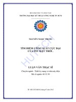
The photo effect
I
The highest fully occupied band is called the valence band
The next highest band, which can be partially occupied or totally
empty, is called the conduction band
The space between VB and CB is called the forbidden band
The energy gap between the band is called the band gap
Conductor band (CB
CB
CB
Forbidden band (FB)
VB
ẬP.<5seV
Valence band (VB)
—---
Conductor
-
FB
{Fe
CB
SeV
VB
VB
Semiconductor
Isolator
FB
rm
5/70
The photo effect
I
Photovoltaic (PV) cells are made of
special materials called
semiconductors such as silicon, which
is currently the most commonly used.
Basically, when light strikes the cell, a
certain portion of it is absorbed within
the semiconductor material. This
means that the energy of the absorbed
light is transferred to the
semiconductor. The energy knocks
electrons loose, allowing them to flow
freely.
Forbidden
band
2
~~
©
Ø2
22O2O©O©QC
co
@
The photo effect
I
Every PV cell has at least one electric field. Without an
electric field, the cell wouldn't work, and this field forms
when the N-type and P-type silicon are in contact.
Right at the junction, electrons and holes mix and form a
barrier, equilibrium is reached, and an electric field
separating the two sides is formed. This electric field acts
as a diode.
=~
orn
7/70
The photo effect
'When light, in the form of photons, hits solar cell, its energy frees
electron-hole pairs. Each photon with enough energy will normally
free exactly one electron, and result in a free hole as well. If this
happens close enough to the electric field, or if free electron and hole
happen to wander into its range of influence, the field will send the
electron to the N side and the hole to the P side. This causes further
disruption of electrical neutrality, and if we provide an external current
path, electrons will flow through the path to their original side (the P
side) to unite with holes that the electric field sent there, doing work
for us along the way. The electron flow provides the current, and the
cell's electric field causes a voltage.
SS
—Si
—
te
como
_
@
Principle of solar cells
I
Not all the energy of photons with wavelengths near the
band gap is converted to electricity. The solar cell surface
reflects a part of the incoming light, and some is
transmitted through the solar cell. Further more, electrons
can recombine with holes.
The spectral response is given by :
SÙ)= Hd)
9/70
€
Principle of solar cells
Ve
I
Ry
Reflection
Rear contact
Ps
‘Transmission
rm
10/70
€
Solar Cell Materials
I
Solar cells can be made from a wide range of
semiconductor materials. They are:
Silicon (Si)—including single-crystalline Si, multicrystalline Si,
and amorphous Si
Polycrystalline thin films—including copper indium diselenide
(CIS), cadmium telluride (CdTe), and thin-film silicon
Single-crystalline thin films—including high-efficiency material
such as gallium arsenide (GaAs)
= ~~
rm
11/70
€
Solar Cell Materials
_
The crystallinity of a material indicates how perfectly
ordered the atoms are in the crystal structure. Silicon, as
well as other solar cell semiconductor materials, can come
in various forms: single-crystalline, multicrystalline,
polycrystalline, or amorphous. In a single-crystal material,
the atoms making up the framework of the crystal are
repeated in a very regular, orderly manner from layer to
layer. In contrast, in a material composed of numerous
smaller crystals, the orderly arrangement is disrupted
moving from one crystal to another. One classification
scheme for silicon uses approximate crystal size and also
includes the methods typically used to grow or deposit
such material.
i
CĐ
rm
12/70
€
Solar Cell Materials
Type of Silicon
Abbreviation | Size Range
Single-crystal silicon
sc-Si
Multicrystalline silicon
Polycrystalline silicon
| mc-Si
pe-Si
Microcrystalline silicon | mc-Si
mmừùäẳẮ
I
| Deposition Method
>10cm
Czochralski, float zone
1mm-10cm _|
Cast, sheet, ribbon
1imm-10mm | Chemical-vapor deposition
<1mm
Plasma deposition
man
13/70
€
Solar Cell Materials
I
Absorption
The absorption coefficient of a material indicates how far light
having a specific wavelength (or energy) can penetrate the material
before being absorbed. A small absorption coefficient means that
light is not readily absorbed by the material. Again, the absorption
coefficient of a solar cell depends on two factors: the material
making up the cell, and the wavelength or energy of the light being
absorbed. Solar cell material has an abrupt edge in its absorption
coefficient. The reason is that light whose energy is below the
material's bandgap cannot free an electron. And so, it isn't
absorbed.
EE
~~
cor
14/70
Solar Cell Materials
I
Bandgap
The bandgap of a semiconductor material is an amount of energy.
Specifically, it's the minimum energy needed to move an electron
from its bound state within an atom to a free state. This free state is
where the electron can be involved in conduction. The lower
energy level of a semiconductor is called the "valence band.“ And
the higher energy level where an electron is free to roam is called
the "conduction band." The bandgap (often symbolized by Es) is
the energy difference between the conduction band and valence
band.
~~
rom
15/70
€
Solar Cell Materials
I
IIINIIIIIñf]
16/70
Solar Cell Types (Silicon)
I
Single-Crystal Silicon
To create silicon in a single-crystal state, we must first melt highpurity silicon. We then cause it to reform or solidify very slowly in
contact with a single crystal "seed.“ The silicon adapts to the
pattern of the single-crystal seed as it cools and gradually solidifies.
Not surprisingly, because we start from a seed, we say that this
process is "growing" a new rod (often called a "boule") of single
crystal silicon out of molten silicon.
Several different processes can be used to grow a boule of singlecrystal silicon. The most established and dependable processes are
the Czochralski (Cz)method and the float-zone (FZ) technique. We
also discuss "ribbon-growth" techniques.
EE
~~
cor
17/70
€
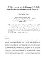
Solar Cell Types (Silicon)
I
Single-Crystal Silicon
The most widely used technique for
making single-crystal silicon is the
Czochralski process, in which a seed of
single crystal silicon contacts the top of
molten silicon. As the seed is slowly raised,
atoms of the molten silicon solidify in the
pattern of the seed and extend the singlecrystal structure.
Sead —
xả
dien
Heater
t
leet
cols a
Crucible
SS
—
com
18/70
Solar Cell Types (Silicon)
Multicrystalline Silicon
Multicrystalline silicon devices are generally less
efficient than those of single-crystal silicon, but they can
be less expensive to produce. The multicrystalline silicon
can be produced in a variety of ways. The most popular
commercial methods involve a casting process in which
molten silicon is directly cast into a mold and allowed to
solidify into an ingot. The starting material can be a
refined lower-grade silicon, rather that the higher-grade
semiconductor grade required for single-crystal material.
The cooling rate is one factor that determines the final
size of crystals in the ingot and the distribution of
impurities. The mold is usually square, producing an
ingot that can be cut and sliced into square cells that fit
more compactly into a PV module.
19/70
€
Solar Cell Types (Silicon)
I
Amorphous Silicon
Amorphous solids, like common glass, are materials whose atoms
are not arranged in any particular order. They don't form
crystalline structures at all, and they contain large numbers of
structural and bonding defects. But they have some economic
advantages over other materials that make them appealing for use
in solar electric, or photovoltaic (PV), systems. Today, amorphous
silicon is common in solar-powered consumer devices that have
low power requirements, such as wristwatches and calculators.
=
rom
20/70