SCHWING CONCRETE PUMP MANUALS
Bạn đang xem bản rút gọn của tài liệu. Xem và tải ngay bản đầy đủ của tài liệu tại đây (28.89 MB, 405 trang )
Home
TOC
Print
OPERATION MANUAL
ORIGINAL INSTRUCTIONS FOR CONCRETE LINE PUMPS
All SP “Rock Valve” Models
Part Number 30100750
Line Pump Division
5900 Centerville Rd
White Bear, MN. 55127
1-888-SCHWING (724-9464)
www.schwing.com
Home
TOC
Print
CALIFORNIA
Proposition 65 Warning
Diesel engine exhaust and some of its constituents are known
to the State of California to cause cancer, birth defects, and
other reproductive harm.
Version
3.0.8
Revision date
05/14
Home
TOC
ORIGINAL OPERATING INSTRUCTIONS FOR
ALL SP ÒROCK VALVE ” MODELS
swg99a001.eps
Part Number 30100750
Version 3.0.8
Copyright © 2014, Schwing
All rights reserved
Home
TOC
Table of Contents
Introduction
Manufacturer’s Statement........................................................................... 8
Safety alert symbol and signal word explanation ................................. 8
How to reach us .................................................................................... 9
How to order parts ................................................................................ 9
Model Number:........................................................................................... 9
Serial Number: ............................................................................................ 9
ID Tag Location........................................................................................ 10
ID Tag ....................................................................................................... 11
If your ID tag is missing ..................................................................... 11
Specifications
Unit Specifications.................................................................................... 14
Hydraulic Pressure Specifications ............................................................ 16
Concrete Pump.................................................................... bar (PSI) 16
Noise emission levels............................................................Decibels 16
Safety
How to Order Additional Safety Manuals ................................................ 18
Product Overview
First Commissioning................................................................................. 22
Installation of your new unit ............................................................... 22
Machine Description................................................................................. 23
Emergency Stop switches ................................................................... 23
Concrete pump hydraulic pumps ........................................................ 24
Concrete Pump Circuit........................................................................ 24
SP Circuit Diagram ................................................................................... 28
Phase A ............................................................................................... 28
Phase B................................................................................................ 30
Phase C................................................................................................ 32
Phase D ............................................................................................... 34
SP 2000 Circuit Diagram .......................................................................... 36
Phase A ............................................................................................... 36
Phase B................................................................................................ 38
Phase C................................................................................................ 40
Phase D ............................................................................................... 42
Phase E................................................................................................ 44
Phase F ................................................................................................ 46
Phase G ............................................................................................... 48
Phase H ............................................................................................... 50
Phase I................................................................................................. 52
Phase J................................................................................................. 54
Phase K ............................................................................................... 56
Component Locations ............................................................................... 58
Hopper Area........................................................................................ 63
iv
Operation Manual - All SP Rock Valve models
revDate
Home
TOC
Table of Contents
Safety Devices .........................................................................................
Emergency Stop Switches..................................................................
Automatic Shut-off Circuit Agitator ..................................................
Safety Valves (Pressure relief valves) ...............................................
Safety Guards.....................................................................................
Fuses ..................................................................................................
Warning Labels ..................................................................................
66
66
66
66
66
66
67
Operation
Preparation ...............................................................................................
Arrive to work on time, with a clear head. ........................................
Have the right machine for the job. ...................................................
Have the equipment that you will need for the job. ...........................
Have the right personal protective equipment for the job..................
Check the equipment before leaving the yard....................................
Towing the unit ........................................................................................
Licensing............................................................................................
Backing up. ........................................................................................
Changing lanes...................................................................................
Loading the unit for shipment............................................................
Unit Setup ................................................................................................
Selecting the proper set up location on the job site. ..........................
Laying out the pipeline ......................................................................
Setting the Stabilizers ........................................................................
Operating the Pump .................................................................................
Basic Troubleshooting .......................................................................
Before the first truck backs up to your hopper ..................................
Lubricate your pipeline. .....................................................................
To control the speed of the unit .........................................................
Pump the job ......................................................................................
Time Constraints................................................................................
To disable the entire unit in an emergency ........................................
Delays ................................................................................................
Keep the waterbox full.......................................................................
Use of the vibrator .............................................................................
Blockages...........................................................................................
Clean-out............................................................................................
Disposing of excess concrete .............................................................
Clean the hopper ................................................................................
Clean the rock valve and material cylinders ......................................
Be careful with acid ...........................................................................
Clean the waterbox ............................................................................
Preparation for travel .........................................................................
Special Pumping Situations .....................................................................
Rod side to piston side pumping (SP 2000).......................................
Quick Clean-out .................................................................................
Cold weather pumping.......................................................................
Preheating the hydraulic oil ...............................................................
Startup 250:Users:Danny:Desktop:Operation manuals:line pumps:All
SP Rock Valve models:Frame files:AllSPRockvalveTOC.fm
Operation Manual - All SP Rock Valve models
70
70
70
70
72
73
74
74
74
74
74
75
75
75
76
76
77
78
81
83
84
85
86
86
86
86
87
87
88
88
92
93
94
95
95
95
96
96
97
v
Home
TOC
Table of Contents
Maintenance
Filtration.................................................................................................. 100
General Information.......................................................................... 100
Specific Information ......................................................................... 100
Hydraulic Oils......................................................................................... 102
General Information.......................................................................... 102
Specific information.......................................................................... 102
Pressure, Hoses and Fittings ................................................................... 102
General Information.......................................................................... 102
Specific Information ......................................................................... 103
General Maintenance Tips ...................................................................... 104
Torque Specifications ....................................................................... 104
Adjusting relief valves. ..................................................................... 104
Removal of safety devices. ............................................................... 104
Preventative Maintenance....................................................................... 105
Daily Maintenance ............................................................................ 105
Weekly Maintenance ........................................................................ 106
Monthly maintenance........................................................................ 107
Quarterly Maintenance...................................................................... 109
Semiannual maintenance .................................................................. 110
Annual maintenance.......................................................................... 114
Scheduled maintenance checklist ........................................................... 115
Unscheduled maintenance ...................................................................... 116
Inspecting hydraulic hoses................................................................ 116
Changing rams .................................................................................. 116
Preparation for long term storage ..................................................... 116
Restarting unit after long term storage.............................................. 116
Tier IV engine Regeneration Control Logic ..................................... 121
Regeneration Monitoring and Warning Levels................................. 122
Appendix
Hydraulic Oil Viscosity Chart ................................................................ 126
Torque Specifications for Metric Bolts................................................... 127
Recommended Emergency Hose Kit ...................................................... 128
Fitting Wrench Sizes............................................................................... 129
Straight Fittings................................................................................. 129
Banjo Fittings.................................................................................... 129
Maintenance checklist............................................................................. 130
Output charts........................................................................................... 131
Using the chart. ................................................................................. 132
Nomograph ............................................................................................. 137
Using a Nomograph .......................................................................... 137
Weld On Ends / Coupling Comparison .................................................. 145
MInimum Pipe Wall Thickness .............................................................. 146
Glossary of Terms................................................................................... 147
Additional Reading Material................................................................... 152
List of Lubricants and Nitrogen.............................................................. 153
vi
Operation Manual - All SP Rock Valve models
revDate
Home
TOC
Table of Contents
End of Life Protocol............................................................................... 156
Startup 250:Users:Danny:Desktop:Operation manuals:line pumps:All
SP Rock Valve models:Frame files:AllSPRockvalveTOC.fm
Operation Manual - All SP Rock Valve models
vii
Home
TOC
Table of Contents
viii
Operation Manual - All SP Rock Valve models
revDate
Home
TOC
Introduction
swg99a001.eps
INTRODUCTION
Manufacturer’s Statement......................................................................... 8
Model Number: .......................................................................................... 9
Serial Number:............................................................................................ 9
ID Tag Location ......................................................................................... 10
ID Tag........................................................................................................ 11
Startup 250:Users:Danny:Desktop:Operation manuals:line
pumps:All SP Rock Valve models:Frame files:Intro.fm
Operation Manual - All SP Rock Valve Models
7
Home
TOC
Introduction
Introduction
This operation manual contains unit specifications,
product overview information, the safety manual,
operation information, and maintenance information
for your concrete pump unit.
Safety alert symbol and signal word
explanation
The triangle with the exclamation point inside is used
to alert you to an important safety point and is called a
safety alert symbol. One of the following signal words
will appear after the safety alert symbol:
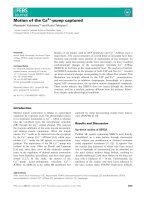
Manufacturer’s Statement
WARNING
Danger
000099.eps
Improper setup / operation creates
hazards. Do not operate this machine
without training. Understand the
warnings in safety manuals and on
decals.
Technical modifications that are made to units will be
documented in each new edition of the operation
manual.
The information contained in the operation manual is
absolutely necessary for the safety, proper setup,
operation, maintenance, and servicing of your concrete
pump. By learning this information and practicing it
every day, you can expect that your concrete pump unit
will give you efficient and reliable service year after
year.
For your own benefit and safety, read the information in
this manual, and follow the instructions to the letter.
Before you operate your concrete pump for the first
time, you should read the operating instructions several
times through. We recommend that you keep a copy
with the concrete pump for quick reference while on
the job site. The general knowledge must be in place
before you arrive on the job site. Any and all persons
who operate a concrete pump must be familiar with the
operating instructions. Even a temporary operator (for
example, if the normal operator is ill or on vacation)
must be familiar with the operation instructions. It
stands to reason that a person who has not operated a
particular concrete pump before will not know how to
safely operate that concrete pump. The machine is built
to the latest technology and safety regulations, but it
may still be dangerous to people and property if it is
operated, maintained, repaired, or used incorrectly.
Warning
Caution
•
•
•
•
If the safety alert symbol is followed by the
signal word DANGER, it indicates a
hazardous situation which, if not avoided,
WILL lead to death or serious injury.
If the safety alert symbol is followed by the
signal word WARNING, it indicates a
potentially hazardous situation which, if not
avoided, COULD result in death or serious
injury.
If the safety alert symbol is followed by the
signal word CAUTION, it indicates a
potentially hazardous situation which, if not
avoided, MAY result in minor to moderate
injury.
The signal word CAUTION used without the
safety alert symbol means the point addresses
a hazard which COULD cause damage to
equipment or property.
The illustrations contained in this manual are intended
to clarify text passages. They may look slightly
different from your unit, but this has only been allowed
if it does not fundamentally change the factual
information.
8
Operation Manual - All SP Rock Valve Models
revDate
Home
TOC
Introduction
Warnings have been placed in the text where needed.
Additional information used with the signal words is
printed in decal format, as shown below, to explain the
specific hazard. Occasionally bold text is used in
addition to the decal for emphasis.
All persons working near the concrete pump unit must
be able to recognize hazardous situations. They must
know how to avoid these situations and how to react
quickly and appropriately whenever hazardous
situations arise.
;;;;;;;;;;
;;;;;;;;;;
Heed the warnings shown on the decals!
Hazard and consequence will be shown
in this space.
000054.eps
DANGER
Hazard and consequence will be shown
in this space.
000057.eps
WARNING
How to reach us
If you encounter a circumstance that is not covered by
this manual, Schwing America’s Service Department
will be more than happy to assist you with all of your
parts and service needs. Call us at either of these #’s:
• Minnesota (main office) (651) 429 - 0999
• Call Center 1- 888-SCHWING (724-9464)
How to order parts
To place an order for spare parts, you can order on line
at schwingparts.com, or you can call our toll free parts
line from anywhere in the continental United States,
except Minnesota. Parts department hours are Monday
through Friday, 6:00 AM to 6:00 PM (central time).
Orders will also be accepted via fax, 24 hours/day.
• Spare Parts 1- 888-SCHWING (724-9464)
• Spare Parts (fax) (651) 429 - 2112
Whenever you call the factory for spare parts or
service, have the model number handy. You can find the
model and serial number on the ID tag that is mounted
to the subframe of the unit. For future reference, the
model number and serial number of your machine can
be found on this page.
NOTE!
CAUTION
000036.eps
Hazard and consequence will be shown
in this space.
When replacing parts always use original
Schwing replacement parts
Model Number:
Serial Number:
Startup 250:Users:Danny:Desktop:Operation manuals:line
pumps:All SP Rock Valve models:Frame files:Intro.fm
Operation Manual - All SP Rock Valve Models
9
Home
TOC
Introduction
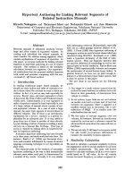
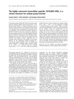
ID Tag Location
The ID tag for this machine is located on the right hand
side of the tongue on the passenger side as shown in
Figure 1.
SWG99a002.eps
Figure 1
Location of ID tag and serial number
10
Operation Manual - All SP Rock Valve Models
revDate
Home
TOC
Introduction
ID Tag
SUBSIDIARY OF
SUBSIDIARIA DE
This product is covered by one or more U.S. patents - see patent decal
MODEL
MODELO
WEIGHT
###
LBS.
PESO
MAX. HYD. PRESSURE
PRESIÓN. HID. MAX.
###
Este producto está cubierto por una o más patentes de Estados Unidos – vea la etiqueta
SERIAL #
# DE SERIE
SP ?????
TONGUE
LBS.
WEIGHT
PESO DE ENGANCHE
###
Sys. 1
GmbH.
Herne / Germany
Phone: (02325) 7871
www.schwing.de
30100673
5900 Centerville Rd
White Bear, MN 55127
Phone: 651-429-0999
www.schwing.com
###
Sys. 2
YEAR
AÑO
123456789
SPM
###
MAX.
MATERIAL
PRESSURE
CPM
###
Sys. 3
200?
###
PSI
PRESIÓN MATERIAL
###
Sys. 4
###
Sys. 5
newSPIDtag.eps
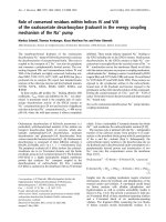
Figure 2
ID Tag and serial number
The ID Tag provides information about the entire unit
the pumpkit, the hydraulic systems, and the year of
manufacture. The unit serial number is on the tag and
also stamped into the subframe directly below the ID
tag, as shown in Figure 2.
NOTE!
All numbers used on ID tag illustrations in
this book are for reference only and should
not be used in any calculations regarding
your unit. For information specific to your
unit, check the ID tag and serial number
affixed to the unit itself as shown in Figure
1.
If your ID tag is missing
If the tag has been removed from the unit and you need
information about your concrete pump unit, read the
unit serial number that is stamped into the steel
subframe. The unit serial number is located on the
tongue directly below the ID tag as shown in Figure 2.
When you locate the number, call the Schwing Service
Department for the information. The unit files are
arranged by this serial number and the service
personnel can find out anything about the unit from the
file that corresponds to this number. New ID tags are
available from the Service Department when you
provide the unit serial number.
Startup 250:Users:Danny:Desktop:Operation manuals:line
pumps:All SP Rock Valve models:Frame files:Intro.fm
Operation Manual - All SP Rock Valve Models
11
Home
TOC
Introduction
NOTES
12
Operation Manual - All SP Rock Valve Models
revDate
Home
TOC
Specifications
swg99a001.eps
SPECIFICATIONS
Unit Specifications ................................................................................... 14
Hydraulic Pressure Specifications ............................................................ 16
Operation Manual - All SP Rock Valve Models
Home
TOC
Specifications
Specifications
Unit Specifications
MODEL
SP 1250
SP 1000 HP
SP 1000
80/55 x 1400:180
90/50 x 1000:150
90/50 x 1000:180
Piston side
Piston side
Piston side
34
26
35
95 yd3/hr
35 yd3/hr
70 yd3/hr
C6.6TA-ECU (Tier3)
129.5Kw (173 Hp)
C4.4TA-ECU (Tier3)
104 Kw (139 Hp)
C4.4TA-ECU (Tier3)
104 Kw (139 Hp)
NA
75 Kw (100 Hp)
75 Kw (100 Hp)
100 Kw
80 Kw
80 Kw
284 L/min (70 gpm)
181 L/min (48 gpm)
246 L/min (65 gpm)
Diesel
2200 rpm
2200 rpm
2200 rpm
Electric
1800 rpm
1800 rpm
1800 rpm
330 bar (4785 psi)
278 bar (4050 psi)
300 bar (4350 psi)
CONCRETE PUMP KIT
Strokes/minute (max.)
Max. Output
Power
Power (Current Electric Motor)
Power (hyd. pumps)
Output (hyd. pumps) Req’d.
Speed (hyd. pumps)
Pressure (max. hyd.)
Theoretical Concrete Output
95
yd3/hr
35
yd3/hr
70 yd3/hr
Max. Pressure on Concrete
64.9 bar (942 psi)
100 bar (1450 psi)
75.8 bar (1100 psi)
Max. Horizontal Pumping Distance
297.8 m (977 ft.)
463.3 m (1520 ft.)
353.6 m (1160 ft.)
Max. Vertical Pumping Distance
86.9 m (285 ft.)
146.3 m (480 ft.)
100.6 m (330 ft.)
Max. Aggregate Size
38.1 mm (1.5 in.)
12.7 mm (0.5 in.)
38.1 mm (1.5 in.)
Min. Concrete Slump
0 mm (0 in.)
0 mm (0 in.)
0 mm (0 in.)
Pumping Cylinder Diameter
177.8 mm (7 in.)
152.4 mm (6 in.)
180mm (7 in.)
Stroke Length
1397 mm (55 in.)
990.6 mm (39 in.)
990.6 mm (39 in.)
Differential Cylinder Diameter
79.8 mm (3.14 in.)
89.9 mm (3.54 in.)
89.9 mm (3.54 in.)
Long Rock
HP Short Rock
Long Rock
1295.4 mm (51 in.)
1295.4 mm (51 in.)
1295.4 mm (51 in.)
Concrete Valve
Charging Hopper Height
Fuel Tank Capacity
189.3 L (50 gal.)
113.6 L (30 gal.)
113.6 L (30 gal.)
Gross Weight
4182 kg (9200 lbs.)
3295 kg (7250 lbs.)
3295 kg (7250 lbs.)
Length
5486.4 mm (216 in.)
4165.6 mm (164 in.)
4165.6 mm (164 in.)
Width
1930.4 mm (76 in.)
1651 mm (65 in.)
1651 mm (65 in.)
Height
2209.8 mm (87 in.)
1879.6 mm (74 in.)
1879.6 mm (74 in.)
30.5 m (100 ft.)
30.5 m (100 ft.)
30.5 m (100 ft.)
Remote Control Cable Length
14
Operation Manual - All SP Rock Valve Models
Home
TOC
Specifications
MODEL
CONCRETE PUMP KIT
Strokes/minute (max.)
Max. Output
Power (Tier3/Stage 3 A engine)
Power (Tier4 engine)
Power (Current Electric Motor)
Power (hyd. pumps)
Output (hyd. pumps) Req’d.
SP 750-18
SP 750-15
SP 2000
SP 500
90/50 x 1000:180
80/50 x 1000:150
120/80 X 1600:200
80/50 x 1000:150
Piston side
Piston side
Piston/Rod side
35
35
30/24
32.5 @ 2500 RPM
70 yd3/hr
50 yd3/hr
91 yd3/hr/118 yd3/hr
45 yd3/hr
C4.4T (Tier3)
75 Kw (100Hp)
C4.4T (Tier3)
75 Kw (100Hp)
C6.6TA-ECU (Tier3)
129.5 Kw (173 Hp)
C4.4T (Tier3)
60 Kw (80 Hp)
C3.4T4i/IIIB
C3.4T4i/IIIB
NA
C3.4T4F/IV
56 Kw (75 Hp)
56 Kw (75 Hp)
113 Kw (150 Hp)
56 Kw (75 Hp)
60 Kw
52 Kw
122 Kw
41 Kw
430 L/min (114 gpm)
193 L/min (50 gpm)
2200 RPM*
240 L/min (65 gpm) 209 L/min (54 gpm)
Diesel
2200 rpm*
2200 rpm*
2300 rpm*
electric
1800 rpm
1800 rpm
1800 rpm
300 bar (4350 psi)
266.7 bar (3867 psi)
300 bar (4350 psi)
266 bar (3867 psi)
70 yd3/hr
50 yd3/hr
118 yd3/hr
45 yd3/hr
75.8 bar (1100 psi)
75.8 bar (1100 psi)
108 bar (1566 psi)/60
bar (870 psi)
76 bar (1100 psi)
Max. Horizontal Pumping Distance
353.6 m (1160 ft.)
353.6 m (1160 ft.)
457 m (1500 ft.)
353.6 m (1160 ft.)
Max. Vertical Pumping Distance
100.6 m (330 ft.)
100.6 m (330 ft.)
121 m (400 ft.)
100.6 m (330 ft.)
Max. Aggregate Size
38.1 mm (1.5 in.)
38.1 mm (1.5 in.)
63 mm (2.5 in.)
38.1 mm (1.5 in.)
Min. Concrete Slump
0 mm (0 in.)
0 mm (0 in.)
0 mm (0 in.)
0 mm (0 in.) 152.4
Pumping Cylinder Diameter
177.8 mm (7 in.)
152.4 mm (6 in.)
200 mm (8 in.)
mm (6 in.) 990.6
Stroke Length
990.6 mm (39 in.)
990.6 mm (39 in.)
1600 mm (63 in.)
mm (39 in.) 79.8
Differential Cylinder Diameter
89.9 mm (3.54 in.)
79.9 mm (3.14 in.)
120 mm (4.75 in.)
mm (3.14 in.) Short
Long Rock
Long Rock
M Rock
Rock 1219.2 mm
1295.4 mm (51 in.)
1295.4 mm (51 in.)
1373 mm (54 in.)
(48 in.) 75.7 L (20
113.6 L (30 gal.)
75.7 L (20 gal.)
189 L (50 gal.)
gal.)
Gross Weight
3357 kg (7400 lbs.)
2994 kg (6600 lbs.)
5724 kg 12,620 (lbs.)
2948 kg (6500 lbs.)
Length
4165.6 mm (164 in.) 4165.6 mm (164 in.)
5816 mm (229 in.)
4318 mm (170 in.)
Speed (hyd. pumps)
Pressure (max. hyd.)
Theoretical Concrete Output
Max. Pressure on Concrete
Concrete Valve
Charging Hopper Height
Fuel Tank Capacity
Width
1651 mm (65 in.)
1651 mm (65 in.)
1930 mm (76 in.)
1676.4 mm (66 in.)
Height
1879.6 mm (74 in.)
1879.6 mm (74 in.)
2373 mm (93.4 in.)
1879.6 mm (74 in.)
30.5 m (100 ft.)
30.5 m (100 ft.)
30.5 m (100 ft.)
30.5 m (100 ft.)
Remote Control Cable Length
* Max RPM of the hydraulic pumps is calculated while the pump is under a full load. Depending on the unit, it is acceptable for
the max RPM to vary slightly from the published estimate.
Operation Manual - All SP Rock Valve Models
15
Home
TOC
Specifications
Hydraulic Pressure Specifications
Oil should be at 40° to 50° Celsius before testing.
Concrete Pump
bar (PSI)
SP-1250
SP-1000HP
SP-1000
SP-750-18
SP-750-15
SP 500
SP-2000
Agitator
Accumulator dump valve
Accumulator secondary relief
Soft switch relief
Stroke limiter circuit
Nitrogen pressure
Noise emission levels
330 (4785)
280 (4050)
300 (4350)
300 (4350)
266 (3867)
266 (3867)
300 (4350)
125 (1812)
200 (2900)
220 (3200)
100 (1450)
0-25 (0-363)
100 (1450)
Decibels
SP 500
SP 750
SP 1000
SP 1250
SP 2000
16
107 dB
110 dB
113 dB
113 dB
113 dB
Operation Manual - All SP Rock Valve Models
Home
TOC
Safety
swg99a001.eps
SAFETY
How to Order Additional Safety Manuals .................................................. 18
Safety Manual (Separate Document) ...........Immediately following page 20
Startup 250:Users:Danny:Desktop:Operation manuals:line
pumps:All SP Rock Valve models:Frame files:Safety.fm
Operation Manual - All SP Rock Valve Models
17
Home
TOC
Safety
Safety
Schwing phone numbers
The information contained in this section of the
operation manual is absolutely necessary for the safe
setup, operation, maintenance, and servicing of your
concrete pump and placing boom.
The Safety Manual is a separate document from the
rest of this manual. Because it is a separate document,
the page numbering and formatting will be different
than the rest of your manual. This was done to allow
the Safety Manual to be inserted in many different
publications while appearing exactly the same in all
places. The Safety Manual has its own alphabetical
index, which is found at the end of the Safety Manual.
•
•
•
•
Spare Parts . . . . . . . . . . . . . . . . . (888) SCHWING
Spare Parts (fax) . . . . . . . . . . . . . .(651) 429 - 2112
Spare Parts (toll free fax) . . . . . . .(877) 554 - 5119
In Minnesota,
or outside of continental U.S. . . . .(651) 429 - 0999
NOTE!
To order manuals, copy the order form
shown on page 20, and Fax it to Schwing at
one of the above numbers, or mail it to:
Schwing Spare Parts Department
5900 Centerville Rd
St. Paul, MN, 55127
How to Order Additional Safety
Manuals
To place an order for additional Safety Manuals (or any
other manual), you can call our toll free parts line from
anywhere in the continental United States except
Minnesota, where you must use the main Schwing
office number. Schwing Spare Parts Department hours
are Monday through Friday, 6:00 AM - 6:00 PM
(Central Time). Orders will also be accepted via fax, 24
hours/day.
We will ship one set of each of the following manuals
free of charge for each unit that is listed with its serial
number and current location:
Safety Manual,
• English: . . . . . . . . . . . . . . . . . . . . . . . . . .30327535
• Spanish: . . . . . . . . . . . . . . . . . . . . . . . . .30381024
Co-worker Safety Rules, laminated,
• English: . . . . . . . . . . . . . . . . . . . . . . . . . .30381022
• Spanish: . . . . . . . . . . . . . . . . . . . . . . . . .30381027
Co-worker Safety Rules, unlaminated,
• English: . . . . . . . . . . . . . . . . . . . . . . . . . .30381023
• Spanish: . . . . . . . . . . . . . . . . . . . . . . . . .30381028
Small line Safety Manual,
• English: . . . . . . . . . . . . . . . . . . . . . . . . . .30381680
• Spanish: . . . . . . . . . . . . . . . . . . . . . . . . .30381841
18
Operation Manual - All SP Rock Valve Models
revDate
Home
TOC
Safety
August 29, 2008
Safety/Service Bulletin 1023-08
Subject: Release of Safety Manual version 6.x.1
Dear Schwing Customer,
The Safety Manual has been updated to version 6.0.1 and has several changes, most of which
pertain to the more common incidents currently being reported in the concrete pumping industry
(hose whipping, tip overs and electrocution). One notable pagination change occurred. The
pipewall thickness chart, which has always appeared on page 73 of the Safety Manual, has been
pushed back to page 75. In the past, releases such as this would include the complete paperback
manual and a non-laminated version of the updated Co-worker Safety Rules. In an effort to “Go
Green”, we have decided to ship a CD containing six PDF files: Version 6.0.1 of Safety Manual
(English & Spanish), version 6.0.1 of the Co-worker Safety Manual (English & Spanish), and
version 6.0.1 of the Line Pump Safety Manual (English & Spanish). This package, as in the past,
also includes an order form for hard copies of any of those documents. Just fill out the attached
form(s) and fax it to us at the number listed. We will ship one set of manuals free of charge for
each unit that is listed with its serial number and current location. Additional manuals are
available at a nominal fee. The Co-worker Safety Rules are available as laminated books intended
to be kept on the pump for easy reference. Please instruct your operators to make the co-worker
information available to the placing crew and laborers, and to read the information to the workers
if they believe the workers wouldn’t understand the printed text. If you are planning any safety
training for your customers, the Co-worker Safety Rules booklet is also available in a nonlaminated version at a fraction of the cost. If you choose to order the un-laminated version, the
part numbers are 30381023 for English and 30381028 for Spanish. You could also print them
yourself from the file on the enclosed disc. Of course, the non-laminated version is not intended to
be kept on the pump. It is our objective to get a copy of each of these publications into the hands
of every operator and the workers around the pump. Please help us make the Safety Manual
effective for jobsite safety by obtaining a copy for each of your operators, and encourage them to
read and understand the rules. Older versions of the manual should be discarded when the new
version is in hand.
Thank you in advance for your consideration in this matter.
Best Regards,
Danny L. Mace
Manager, Product Safety Department
Schwing America, Inc.
safemanbulletinletter.fm
Startup 250:Users:Danny:Desktop:Operation manuals:line
pumps:All SP Rock Valve models:Frame files:Safety.fm
Operation Manual - All SP Rock Valve Models
19
Home
TOC
Safety
a
Safety Manual v 6.0.1 Order Form
Please complete this form and mail to:
Or send via fax to:
Fax # (651) 429 - 8261
(publications dept.)
5900 Centerville Road
White Bear, Mn. 55127
Telephone (651) 429-0999
Attention: Publications
Company:
Street Address:
We cannot ship manuals to a P.O. box
City, State, Zip:
Phone (
Attention:
)
Manual part number:____________________
Model number:
Manual part number:____________________
Serial number:
Manual part number:____________________
Model number:
Manual part number:____________________
Serial number:
Manual part number:____________________
Model number:
Manual part number:____________________
Serial number:
Manual part number:____________________
Model number:
Manual part number:____________________
Serial number:
Manual part number:____________________
Model number:
Manual part number:____________________
Serial number:
Safety Manual, Bound, English v 6.0.1 ..................................................................................
Safety Manual, Bound, Spanish v 6.1.1 ..................................................................................
Co-worker, Bound & Laminated, English v 6.0.1 ....................................................................
Co-worker, Bound & Laminated, Spanish v 6.1.1 ..................................................................
Line Pump, Bound, English v 6.0.1 .........................................................................................
Line Pump, Bound, Spanish v 6.1.1 .......................................................................................
Feel free to copy or otherwise reproduce this form if more copies are needed.
20
Operation Manual - All SP Rock Valve Models
Part #30327535
Part #30381024
Part #30352799
Part #30381027
Part #30381680
Part #30381841
internal250:servicebulletins:601order form.ai
revDate
Home
TOC
Overview
swg99a001.eps
OVERVIEW
First Commissioning ................................................................................. 22
Machine Description ................................................................................. 23
SP Circuit Diagram ................................................................................... 28
SP 2000 Circuit Diagram .......................................................................... 36
Component Locations............................................................................... 58
Safety Devices .......................................................................................... 66
Startup 250:Users:Danny:Desktop:Operation
manuals:line pumps:All SP Rock Valve models:Frame
Operation Manual - All SP Rock Valve Models
21
Home
TOC
Overview
Product Overview
First Commissioning
Installation of your new unit
When your new Schwing was delivered, it was
accompanied by several documents in addition to this
operation manual. One of those important documents is
called the “DELIVERY INSPECTION REPORT”.
Each of the applicable 35 items listed should be
checked before your new pump is sent to the first job.
Operational
Repair
Required
Comments*
(If repair is required)
1. Engine Coolant
2. Engine oil level
3.Transmission oil level
4. Oil level system l and ll
5. Oil level system lll
6. Transfer case or FTD oil level
7. Oil in gear compartment of Hyd. Pump 1
8. Oil level in dist. gear box (banana pumps)
9. Oil level in agitator gear box
10. Flushing oil level (gate valve system)
11. Oil level in compressor
12. Agitator greased
13. Rock valve greased (if equipped)
14. Drive line greased
15. Outriggers & boom greased
16. Manual & remote throttles set to proper
RPM (
RPM)
17. Setting of relief valve system l
18. Setting of relief valve system ll
19. Setting of relief valve system lll
20. Pressure gauges work system l&ll&lll
21. Hydraulic lines checked for leakage
(heat oil to 80˚ c)
22. Hydraulic oil cooler checked for
leakage and proper air flow
23. Water pump
24. Agitator
25. Forward-reverse for pumpkit
26. Outriggers
27. Remote control (boom) functions
28. Manual check of all hand valves
29. Holding valves on boom
30. All boom pin retainers in place
31. End hose cable hook installed
32. Tail light and clearance lights
33. Safety decals (see decal sheet)
34. Tools/Spare Parts (see tool check list)
35. Visual inspection of paint job
* Please note any other comments on back of white copy
22
Operation Manual - All SP Rock Valve Models
revDate
Home
TOC
Overview
Machine Description
It is recommended that you read this section of the
manual while you are near the concrete pump so that
you can identify the components that are discussed.
The Schwing trailer-mounted concrete pump is
mounted on a trailer chassis. The pump is hydraulically
or electrically driven.
Emergency Stop switches
Pressing one of the RED EMERGENCY PUSH STOP
switches (Figure 3) will stop the engine.
SWG98n135.eps
Figure 3
Emergency Stop Switches (4)
Startup 250:Users:Danny:Desktop:Operation
manuals:line pumps:All SP Rock Valve models:Frame
Operation Manual - All SP Rock Valve Models
23