Marine engineering vol 2 part 16
Bạn đang xem bản rút gọn của tài liệu. Xem và tải ngay bản đầy đủ của tài liệu tại đây (2.62 MB, 62 trang )
MARINE ENGINEERING PRACTICE
Volume 2
Part 16
SHIP'S GEAR:
A REVIEW OF DECK MACHINERY
by
D. H. BEATTIE
and W. M. SOMERVILLE
THE INSTITUTE OF MARINE ENGINEERS
Published by The Institute of Marine Engineers
80 Coleman Street
London
EC2R 5BJ
Copyright © 1978 The Institute of Marine Engineers
A Charity Registered in England and Wales
Reg. No. 212992
Reprinted 1991
Reprinted 1994
Reprinted 1998
Reprinted 2000
All rights reserved. No part of this publication may be reproduced, stored
in a retrieval system, or transmitted in any form of by any means, electronic,
mechanical, photocopying, recording or otherwise, without the prior
permission of the publisher. Enquiries should be addressed to The Institute
of Marine Engineers.
ISBN: 0 900976 78 0
Printed by Hobbs the Printers in the UK
CONTENTS
1.
1.1
1.2
1.3
2.
2.1
2.2
3.
3.1
3.1.1
3.1.2
3.2
3.3
3.3.1
3.3.2
3.3.3
4.
4.1
4.2
4.2.1
4.2.2
4.2.2.1
4.2.2.2
4.2.2.3
4.2.2.4
4.2.2.4.1
4.2.2.4.2
4.2.2.4.3
5.
5.1
5.2
5.3
5.4
5.5
5.6
5.7
5.8
5.9
5.9.1
5.9.2
5.9.3
5.9.4
5.9.5
5.9.6
6.
Anchor Handling Equipment
Windlasses
WinchWindlass
Anchor Capstan
Mooring Equipment
Non-automatic MooringWinches
Automatic MooringWinches
Cargo Handling Equipment
Derrick Rig Systems
Fixed Outreach Systems
SwingingDerrick Rigs
Heavy Lifting Systems
Deck Cranes
Cargo Cranes (hook)
Twin Cranes
Grabbing Cranes
Control of Deck Equipment
Steam
Electrical Control Systems
Direct Current Supplies
AC Systems
Squirrel CageMotors
Wound Rotor Induction Motors
Ward Leonard Controls for AC Ships
Electronic Control Systems
Electronic Control of Ward Leonard Systems
Direct Electronic Control of AC Motors
Direct Electronic Control of DC Motors
Maintenance
General
Motor Bearings
Squirrel CageInduction Motors
Wound Rotor Induction Motors
DC Motors
Ward Leonard Sets
Brakes
Cable terminations
Controls
Open Contactors
Block Contactors
Relays
Resistances
Rectifiers
Thyristors
Fault fmding
Page
1
I
2
2
4
4
4
6
6
6
7
7
10
10
10
13
17
17
18
18
24
24
27
30
35
37
39
39
46
46
46
47
47
48
49
49
51
51
52
53
53
54
55
55
57
LIST
FIG.
FIG.
FIG.
FIG.
FIG.
FIG.
FIG.
FIG.
FIG.
FIG.
FIG.
FIG.
FIG.
FIG.
12345678910 11 12 13 14 -
OF ILLUSTRATIONS
Typical windlass arrangement.
Typical winch/windlass arrangement.
Typical anchor capstan arrangement.
Union purchase rig.
Patented swinging derrick system.
Heavy derrick rig.
Patented heavy lift derrick.
A S-ton deck crane.
Two 1S-ton twin deck cranes.
Heavy lift deck crane combined with S-ton deck crane.
Typical electro-hydraulic grab.
Typical 4-rope grab.
Steam valves for one double acting cylinder of a two-cylinder steam engine.
Back pressure valve for automatically regulating differential pressure across
mooring winch engine.
FIG.15 - Relationship between speed and load for shunt, series and compound d.c. motors
at rated supply voltage.
FIG.16 - Variation of speed with load for various resistances in series with shunt motor
armature at fixed field strength.
FIG. 17 - Contactor switched series resistance control of D.C. winch.
FIG. 18 - Single-speed A. C. motor reversing drive.
FIG. 19 - Typical torque/speed curves for single and double-cage rotor induction motors.
FIG. 20 - Two-speed reversing power circuit for A.C. motor with independent windings.
FIG. 21 - Two-speed reversing power circuit for A.C. motor with tapped winding.
FIG. 22 - Schematic diagram for three-speed pole-changing cargo winch induction motor.
FIG. 23 - Typical load/speed characteristics for a slipring induction motor with rotor
resistance control.
FIG. 24 - A. C. slipring motor control system for windlass drive.
FIG. 25 - Basic Ward Leonard control system.
FIG. 26 - Speed/load characteristic of basic Ward Leonard system.
FIG. 27 - Modified Ward Leonard control system.
FIG. 28 - Speed/load characteristic of modified Ward Leonard system.
FIG. 29 - Control schematic for hoist, luff and slew motions of Ward Leonard driven
deck crane.
FIG. 30 - Differential crane limit switch arrangement.
FIG. 31 - Slack rope switch.
FIG. 32 - A selection of thyristors, illustrating range and encapsulation.
FIG. 33 - Typical thyristor characteristics.
FIG. 34 - The control of voltage and power by delaying the thyristor gate signal.
FIG. 35 .. Schematic power circuit for the thyristor control of a Ward Leonard drive.
FIG. 36· Thyristor and diode reversing drive for squirrel cage induction motor.
FIG. 37 - Back-to-back thyristor reversing drive for slipring induction motor.
FIG. 38 - Torque/speed curves for thyristor-controlled induction motor drive.
FIG. 39 - Full bridge thyristor power circuit.
FIG. 40 - Phase and d.c. voltages relating (0 full thyristor bridge at firing pulse delays of
0° 30° 60° 90° and 120°.
FIG. 41 - Transformer-fed half-bridge circuit.
FIG.42 - Voltage-wave form from controlled transformer-fed half bridge.
FIG. 43 -Armature reversing thyristor motor control scheme.
FIG. 44 - Field reversing thyristor motor control scheme.
FIG.45 - 'Back-to-Back' bridge or 'static' thyristor motor control scheme.
FIG. 46 -A Typical Arrangement of one type of watertight motor brake.
The authors would like to thank the undernoted
permission to reproduce illustrations.
FIG. I
FIG. 2
FIG. 3
FIG. 4
FIG. 5
FIG. 6
FIG. 7
FIG. 8
FIG. 9
FIG.10
FIG. 11
FIG. 12
companies for their kind
Clarke Chapman Marine
Clarke Chapman Marine
Clarke Chapman Marine
Clarke Chapman Marine
Cargospeed Equipment Ltd.
British Standards Institution
Blohm & Voss A. G.
Clarke Chapman Marine
Clarke Chapman Marine
Clarke Chapman Marine
Clyde Booth - Rodley
Butters Cranes Ltd.
INTRODUCTION
This booklet describes electrical and steam-powered machinery
including its control system. Hydraulic power transmission is covered
in Marine Engineering Practice Volume I Part 7 - Hydraulic Power
Transmission in Marine Machinery by C.M. Joy C.Eng. and electric
power is covered in Electricity Applied to Marine Engineering by
W. Laws.
The range of deck machinery currently in use is extensive and varied to
suit the owner's particular requirements. However, the equipment generally used
can be classified into three categories:
1) Anchor handling equipment;
2) Mooring equipment;
3) Cargo handling equipment.
Although other types of deck machinery are in use e.g. towing winches,
trawl winches, etc, it is not the intention to discuss these highly specialized
machines, but merely to describe, in general terms, the type of equipment to
be found on the decks of most modern vessels.
1. ANCHOR HANDLING EQUIPMENT
1.1 WINDLASSES (see Fig. 1)
The efficient working of the anchor windlass is essential to the safety of
the ship and therefore its design and performance is subject to the approval of
the appropriate classification society. Classification society rules governing
windlass performance vary. Basically they require that:
a) the windlass cable lifter brakes are able to control the running anchor
and cable when the cable lifter is disconnected from the gearing during
"letting go"; average cable speeds vary between 5-7.5 m/s (1000-1500)
during this operation;
b) the windlass can heave a certain weight of cable at a specified speed;
this "full load" varies but is generally between 4 and 6 times the weight
of one anchor and the speed of haul at full load is usually between
0.12-0.2 m/sec (25-40 ft/min).
The normal windlass arrangement utilizes one prime mover to drive two
declutchable cablelifters and also two warping ends. The warping ends are not
declutchable and rotate continuously when the windlass is in use. When mooring,
light line speeds of 0.75-1.0 m/sec (150-200 ft/min) are required.
Due to the low speed of rotation
of the cablelifter whilst heaving anchor
(2-7 rev/min), a high gear reduction is required when the windlass is driven by
a high-speed electric or hydraulic motor. This reduction is generally obtained
by the use of a high-ratio worm gear, followed by one or two steps of spur
gearing between the warping end shaft and the cable lifter . Alternatively,
multi-steps of spur gearing are used.
As windlasses. are required for intermittent
duty only, the gearing is
designed with an adequate margin on strength rather than wear. Slipping clutches
are commonly fitted on electrically driven windlasses, either between the motor
and the gearbox or incorporated in the gearbox. This avoids the inertia of the
driving motor being transmitted through the gear system in the event of shock
loading on the cable. Such shocks can occur, for example, when the anchor is
pulled hard into the hawse pipe when being housed.
Windlasses are normally controlled from a local position, the operator
manually applying the cablelifter brake, as required, to control the speed of the
running cable. Whilst heaving anchor, the operator is positioned at the windlass
or at the ships side if he needs to watch the anchor being housed. Remotely
cOntrolled systems are available which permit all normal windlass functions to
to be carried out from the bridge, thus obviating the need for crew members to
be on standby duty on the forecastle for long hours while the ship is negotiating
an estuary or other restricted waterway.
The windlass is in the most vulnerable position as far as exposure to the
elements is concerned and should be designed and constructed so that maintenance is reduced to the absolute minimum. Normally primary gearing is enclosed
and splash lubricated, maintenance being limited to pressure grease points for
gunmetal sleeve bearings. However, due to the large size of the final set of bevel
or spur reduction gears, and the clutching arrangements required, these gears
are often of the open type and are lubricated with open gear compound.
1.2. WINCH WINDLASS UNIT
This arrangement (Fig 2) uses a forward mooring wi!1ch to drive a windlass
unit thus reducing the number of prime movers required. The port and starboard
unit can, if required, be interconnected mechanically by means of clutches to
provide the following facility:
a)
b)
a standby drive should one prime mover fail;
the power of both prime movers to one windlass should this be
required.
1.3 ANCHOR CAPSTAN
With this type of equipment the driving machinery is situated below deck and
the cablelifters are mounted on ve"rtical shafts. The capstan barrel may be
mounted on top of the cablelifter but on larger equipment above 76 rom (3 in.)
diameter cable - it is usual to have the capstan barrel mounted on a separate
shaft as shown in Fig. 3.
2
2. MOORING EQUIPMENT
These are, at the present time, no accepted Classification Society rules for
the selection of mooring equipment, the size and type of equipment adopted
for a vessel generally being based on past experience. However, certain independent authorities and major oil companies have instituted their own investigations
into the question of mooring techniques and equipment and a basis for selection
of tanker mooring equipment is available. Hauling load duties of warping capstans
and mooring winches vary between 30-300 kN (3-30 tons) at 0.3-0.6 m/sec
(60-120 ft/min) and twice full load is normally provided for recovering light
lines.
The size of wire rope used on mooring winch barrels is limited by the weight
of wire manageable by the crew; this is currently accepted as 48 mm (2 in )
diameter maximum. The basic problems associated with the use of wire ropes
is that they are difficult to handle, they do not float and when used in multilayers, due to inadequate spooling, the top tensioned layer cuts down into the
underlying layers causing damage. In order to counteract this latter problem, a
divided barrel can be used so that the wire may be stored in one portion and a
single layer of wire transferred to the second portion when tensioned. The low
density, high breaking strength synthetic rope (polypropylene, nylon, terylene,
etc.) offers certain advantages over the wire rope, its one main disadvantage
being a tendency to fuse if scrubbed against itself or the barrel. These ropes are
currently in use with double drum warping equipment and storage reels on
tankers and bulk carriers.
The fitting of synthetic ropes direct to mooring barrels is also currently being
tested in practice, apparently with some success.
Mooring winches are currently manufactured with steam, electric or hydraulic
drives. The two basic types are described below.
2.1. NON-AUTOMATIC MOORING WINCHES
These winches provide the facility for tensioning the hauling wire up to the
stalling load of the winch, usually 1.5 time the hauling load; thereafter the
load is held by the prime mover brake or preferably by the barrel brake with
the barrel de-clutched. The winch cannot payout
wire unless the brake is
overhauled (when the rope tension overcomes the braking torque) or recover
wire unless manually operated. Thus wire will become slack during service unless
constantly attended, because of tidal variations, loading/unloading, etc.
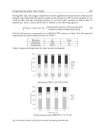
2.2. AUTOMATIC MOORING WINCHES
These winches provide the maRual control facilities of the non-automatic
winches. However, in addition they incorporate a control feature such that, in
the "automatic" setting, the winch may be overhauled and wire is paid off the
barrel at a predetermined maximum tension. In addition, wire is recovered at
a lower tension should it tend to become slack. Thus there is a certain range of
4
tension associated with each step of automatic control when the wire is stationary;
it is not desirable to reduce this ran~e to the minimum possible as this results in
hunting of the controls.
It should be noted that the principal reason for incorporating automatic controls
as described is to limit the tension at which the winch automatically renders
the wire so avoiding broken wires and also preventing mooring wires becoming
slack.
The load sensing devices used with automatic mooring winches are varied and
cannot be described here in detail.
Spring loaded gearwheels and torsion bars are widely used for sensing variations
in rope tension with steam and electric winches. With this "dead motor" system,
the prime mover is normally un~nergized and only becomes active in response
to predetermined variations in rope tension.
Conversely, the "live motor" system makes use of a prime mover which is
continuously energized in the hauling mode. With steam and hydraulic mooring
winches, pressure sensing devices can be used and the motor current can be
monitored with electric winches.
The control system for an electric mooring winch is described in part 2 of this
part.
Mooring winches are usually controlled from the local position i.e. at the winch.
However, on vessels of large beam, such as tankers or where docking operations
are a regular occurrence (for example, with vessels regularly navigating the St.
Lawrence Seaway), remote and shipside controllers are of great advantage. As
mooring techniques vary so widely the position and type of control must be
engineered to suit the application. It is considered, especially on vessels where
mooring lines may be long and ship position critical, that the greatest asset
to the operator is knowledge of the wire tensions existing during the mooring
operation, coupled with an indication of the amount of wire paid off the barrel:
It is quite feasible to record these at a central position and mooring lines would
then only have to be adjusted periodically as indicated by the recording instruments. At present, this practice is used extensively on oil drilling rigs but could
be developed for mooring ships.
The majority of automatic mooring winches are of spur geared design in order
to improve the backward efficiency of the gear train for reversing purposes,
the gearing and bearings being totally enclosed and splash lubricated from the
oil sump. On larger mooring winches for VLCC it is now common practice to
design the brake to withstand the breaking load of the mooring wire, although
British Standard Specification BS.MA 32 only calls for a holding load of not less
than 80 per cent of the breaking strength pf the rope. Worm geared automatic
mooring winches are uncommon as the low forward, backward and standstill
efficiencies associated with this type of gearing create design and operational
problems.
3. CARGO HANDLING EQUIPMENT
Everything on board a modern cargo ship is geared to achieve the shortest
possible port turnround time and this requirement is especially applicable to its
cargo handling equipment.
Broadly speaking cargo handling can be divided into the following categories.
3.1. DERRICK RIG SYSTEMS
Although gradually being ousted by deck cranes, this system has been the
most popular method of handling cargo since the conception of the modern
cargo vessel and even before that.
Derricks rigs are usually based on the fixed outreach or swinging derrick system.
3.1.1. Fixed Outreach Systems
The union purchase system (Fig. 4) is the most common fixed outreach
system. The system utilizes two derricks and two winches with the derricks in
fixed positions. One derrick is arranged over the quayside and the other over
the hold. By a combination of hoisting on both winches and hoisting on one
winch and paying out on the other winch it is possible to transfer from the
quayside to the hold or vice versa. Although it may appear crude, this system has
been a tried favourite for years but it has several important disadvantages:
I)
2)
It can only be used between a fixed point on the quayside and a
fixed point in the hold; this creates a serious problem of manhandling
the cargo into its stowed position;
Due to the sharing of the load between two derricks, overloading of
one derrick can occur if the operation is not properly managed and
arising from this, many harbour authorities have expressed their
concern about its use.
3.1.2. Swinging Derrick Rigs
Many patent swinging derrick rigs have appeared over recent years (see Fig. 5).
All these rigs have been developed to enable accurate "spotting" of the load.
These designs usually (but not always) include a hoisting, topping and slewing
winch and many ingenious ideas have been devised to overcome or alleviate
the stability problem which can arise when the derrick is in certain attitudes
(usually the outboard position).
Whilst these rigs can perform all the. functions of a deck crane they have the
basic disadvantage of being confined to one hatch, i.e. they cannot slew through
0
360 • The rewards will be great for the inventor who can overcome this defect
and no doubt many minds are already on the problem.
3.2. HEAVY LIFTING SYSTEMS
The conventional method of lifting heavy loads is shown in Fig. 6 and
consists of one or two hoisting winches lifting on a multi-fall system. In addition,
the topping and slewing motions operate thrQugh a multi-part rope system to
ensure control of the load ilt all time.
The introduction of patented heavy lift systems (and the introduction of heavy
deck cranes) has created a decline in the heavy lift derrick. A typical patented
heavy derrick is shown in Fig. 7.
With this system loads up to 300 tons can be lifted and it has the unique
advantage of be~ng able to operate in two holds as the derrick (in the unloaded
condition) is capable of being traversed between the derrick posts.
The load is raised on two winches through multi-part tackle on an endless rope
principle.
A similar system of two winches is used for topping and slewing such that when
both winches heave the derrick will rise -and when one winch is heaving and the
other paying out the derrick will slew. Recent new buildings have been fitted
with two of these patented heavy lifting derricks and with the use of a lifting
beam connected to the two hooks it is possible to lift loads of up to 600 tons.
Special precautions have to be taken when lifting loads of this magnitude to
ensure adequate stability of the vessel and correct functioning of ships equipment
as angles of inclination of up to 17~0 are often encountered.
7
3.3. DECK CRANES
Historically this is the most recent method of handling cargo onboard ship.
In spite of the. fact the deck cranes have been known for some time (in the
literature advertising the maiden voyage of Titanic, mention is made of the fast
electric cranes for handling passenger's baggage) nevertheless they were slow to
be widely adopted. Thanks mainly to Scandinavian ship owners, this resistance
has been broken and even the most conservative shipping companies are turning
to deck cranes.
3.3.1. Cargo Cranes (Hook)
A few years ago cargo cranes rarely exceeded 20 tonnes lifting capacity. Today,
with increased volume of heavy machinery being tansported, particularly to the
emerging nations where port facilities are often totally inadequate or non-existent,
the advantages of the deck crane have proved to be very useful. With its facility
for accurately "spotting" cargo, readiness for action and requiring only one
operator, the deck crane has now firmly established a place for itself and it is
quite common to see a ship's outfit of six cranes which can range in size from 5
to 40 tonnes capacity.
As can be seen in Fig. 8, a typical crane consists of a jib which can be lowered to
the horizontal for stowage purposes, and a hoisting unit which can be on a single
fall of rope or multi falls dependin§ on the lifting capacity. Facility is provided
for slewing the crane through 360 , but limit switches are usually provided to
restrict rotation if there are deck obstructions.
Cranes are mostly of the "self contained" type utilizing the available ship's
electrical supply to operate a suitable motor for driving a Ward Leonard
Generator or a hydraulic power pack. Power is then supplied to individual
motors for hoisting, luffing and slewing. Only occasionally does one see cranes
using a.c. squirrel cage motors, although they are becoming popular in Japan.
3.3.2. Twin Cranes
The introduction of the twin crane is without doubt, the greatest innovation
in the deck crane and heavy lift market.
The basic idea, like all great ideas, is extremely simple and consists of two
independent cranes of equal capacity mounted on a common platform which
can be rotated independently (see Fig. 9).
Each crane can be used individually for normal cargo working, but when a heavy
lift is required the jibs are slewed parallel to each other and a lifting beam is
connected between the cargo hooks. Special arrangements are usually made to
synchronize the hoisting and luffmg motions of the two cranes and with this
arrangement it is pOSSible (ignoring for the moment the weight of the lifting
beam) to lift a load of twice the safe working load of one crane.
When operating in the twin mode, the individual slewing motions are rendered
inoperative and only the platform slewing motion can be used. Although with
twin crane arrangements the cranes involved are of equal capacity and identical
speeds, a variation of the idea has been used with cranes of unequal capacity.
10
The circumstances arise when a heavy lift crane (say 50 tonnes) is required to
operate in two holds and a smaller crane (say 5 tonnes) is required to operate
in the hatch not being used by the hea~ lift crane.
The heavy lift crane is mounted concentric with the crane foundation (see
Fig. 10) to reduce the loading and the light crane is offset. With this system the
cranes do not work in tandem, but nevertheless the facility for using the heavy
lift crane in either hold outweighs the cost involved.
11
3.3.3. Grabt>ing Cranes
With the increasing numbers of dry bulk carriers, it was inevitable that cranes
(and derrick rig systems) with the facility for using grabs would be required.
Originally, these cranes were normal ~argo cranes adapted for grabbing duties.
These adaptations consisted in the beginning, of fitting dumping or hand
released grabs operating on a single fall of rope. Due to the slowness of operation,
limitation of size and inability to handle cargoes such as iron ore, rock phosphate.
etc. these grabs have now almost disappeared.
13
The electro-hydraulic grab (see Fig. 11), which has been steadily replacing the
dumping and hand released type of grabs, has several good features:
1)
2)
3)
high payload/weight ratio;
no shock loading during closing or opening;
easily fitted to existing cranes.
FIG. 11 - Typical electro-hydraulic grab.
Without doubt, however, the real work-horse in the marine grabbing field is
the rope operated grab, which is based on the well proven principle used on land
based cranes.
14
Two rope drums are used. One rope drum holds the grab stationary during the
opening and closing action. The other drum controls the opening and closing
of the grab. When the grab is being hoisted or lowered both drums operate
simultaneously.
Refinements in the control system ensure that the grab remains closed when
being hoisted in "closed" position and open when being lowered in the "open"
position.
The most common arrangement utilizes four ropes, Le. two holding ropes and
two closing ropes (see Fig. 12).
Holding
rop
fixed to grab
----,,_,
Closing rope rfleved
thro
necessary closing
action
Clam shell jaws
FIG.12 - Typical 4-rope grab.
15
Pre-programmed grabbing cycles have been introduced to reduce operator
fatigue and increase output but to date they have not been used extensively.
REFERENCES
British Standard: Marine Series:
"Glossary of Terms and Graphical Symbols for Ship's Deck Machinery"
B.S. MA30;
"Ships' Deck Machinery - Cargo Winch" B.S. MA31;
"Ships' Deck Machinery - Mooring Winches" B.S. MA32;
"Ships' Deck Machinery - Warping Winches" B.S. MA33;
"Ships Deck Machinery - Capstans" B.S. MA34.
For background on the design methods used by the manufacturers of the
equipment, interested readers are referred to the standard works on the theory
of machines, mechanics, structural design, etc.
16
4. THE CONTROL OF DECK EQUIPMENT
Since all traditional deck equipment has been evolved to assist manual effort
in the handling of ship and cargo it is reasonable that, with the introduction of
power to drive the machinery, the aim has been for the control systems to
simulate the continuous speed control and load limiting characteristics of human
muscle.
4.1. STEAM
The first introduction of power was in the form of the steam engine with
single or multiple double acting cylinders. In the simplest form reversing was
obtained by the classic Stephensons link mechanism, and control obtained by
throttling the steam through an adjustable supply valve. The natural characteristic
of these steam engines was self regulating as the greater expansion of the steam
on light load gave higher speeds. Conversely, as the load increased the speed
decreased and the winch would stall safely if overloaded.
It was also relatively easy to requce the steam flow to a winch so as to hold
a suspended load by maintaining pressure against piston and valve leakage.
Foot-operated brakes were added to give better control in operation and, where
required, manual screw-applied brakes were fitted to provide holding effort.
As ship sizes increased the maintenance of steam lines on deck became more of
a problem, and the introduction and increasing use of motor ships led to a
decline in the use of steam in favour of electrical drives, except in certain
situations where the risk of fire or explosion precluded the use of electricity for
example, on the main deck of tankers.
The modem steam engine controls are readily recognisable as variants of the
basic form, engineered for greater reliability.
Steam admission to the cylinder is usually by a double piston valve moved by an
eccentric fixed on the crankshaft. This type of valve is pressure balanced and the
engine can be reversed by a similar valve, controlled by a hand lever, which reverses the steam and exhaust connections to the cylinders. A typical arrangement of reversing and engine valves is shown in Figure 13.
When steam engines are used on mooring winches the same controls are provided,
but an additional valve is required to control the tension in the mooring line
when stalled. The engine is set to heave and the inlet valve is opened fully.
The pressure on the exhaust side of the engine is controlled by a "back pressure
valve" to maintain a pressure differential across the piston which corresponds to
the required mooring line tension.
In its simplest form the back pressure valve may be held shut by a spring of
adjustable force; hence it is able to open when the exhaust pressure on the top
of the valve is sufficient to overcome the spring. PressUI"C
in. ,.the
axhaust port
t jl~
';',
of a stalled steam engine is provided by the small, but ever present, leakage of
steam from the high pressure line past pistons and valves.
17
FIG. 13 - Steam valves for one double acting cylinder of a two-cylinder steam engine.
Other demands on the steam supply can cause fluctuations in the main line
pressure and, since the exhaust pressure is fIxed by the spring setting, it follows
that differential pressure, and hence tension, will vary. To counteract this
tendency the back pressure valve may be made to accept line pressure steam on a
driving piston which supplements or replaces a weaker spring. The driving
piston of the back pressure valve is provided with a small controlled leak so that
the closing force may be regulated by a flow control valve in the feed from the
steam line. With this type of valve, illustrated in Figure 14, the exhaust pressure
is reduced or increased in sympathy with the supply pressure, and thus the
differential pressure on the pistons and tension are maintained more constant.
4.2. ELECTRICAL CONTROL SYSTEMS:
4.2.1. Systems with direct current supplies
The fIrst ships to use electrical power were equipped with direct current
generators supplying fIxed voltage busbars that fed all services on board.
Widespread use of direct current was made prior to 1940.
18