ADAU Audio Codecs from analog device
Bạn đang xem bản rút gọn của tài liệu. Xem và tải ngay bản đầy đủ của tài liệu tại đây (3.32 MB, 69 trang )
Quad ADC with Diagnostics
ADAU1977
Data Sheet
FEATURES
GENERAL DESCRIPTION
Programmable microphone bias (5 V to 9 V) with diagnostics
Four 10 V rms capable direct-coupled differential inputs
On-chip PLL for master clock
Low EMI design
109 dB ADC dynamic range
−95 dB THD + N
Selectable digital high-pass filter
24-bit ADC with 8 kHz to 192 kHz sample rates
Digital volume control with autoramp function
I2C/SPI control
Software-controllable clickless mute
Software power-down
Right justified, left justified, I2S justified, and TDM modes
Master and slave operation modes
40-lead LFCSP package
Qualified for automotive applications
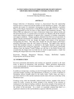
The ADAU1977 incorporates four high performance analog-todigital converters (ADCs) with direct-coupled inputs capable of
10 V rms. The ADC uses multibit sigma-delta (Σ-Δ) architecture
with continuous time front end for low EMI. The ADCs can be
connected to the electret microphone (ECM) directly and provide the bias for powering the microphone. Built-in diagnostic
circuitry detects faults on input lines and includes comprehensive
diagnostics for faults on microphone inputs. The faults reported
are short to battery, short to microphone bias, short to ground,
short between positive and negative input pins, and open input
terminals. In addition, each diagnostic fault is available as an
IRQ flag for ease in system design. An I2C/SPI control port is
also included. The ADAU1977 uses only a single 3.3 V supply.
The part internally generates the microphone bias voltage. The
microphone bias is programmable in a few steps from 5 V to 9 V.
The low power architecture reduces the power consumption.
An on-chip PLL can derive the master clock from an external
clock input or frame clock (sample rate clock). When fed with
a frame clock, the PLL eliminates the need for a separate high
frequency master clock in the system. The ADAU1977 is
available in a 40-lead LFCSP package.
APPLICATIONS
Automotive audio systems
Active noise cancellation system
AVDD2
AVDD3
AVDD1
VBAT
SW
VBOOST_IN
VBOOST_OUT
FUNCTIONAL BLOCK DIAGRAM
ADAU1977
BOOST
CONVERTER
IOUT 50mA
PGND
PROGRAMMABLE GAIN
DECIMATOR/HPF
DC CALIBRATION
ATTENUATOR 14dB
AIN1P
AIN1N
AIN2P
AIN2N
AIN3P
AIN3N
AIN4P
ADC
ADC
ADC
ADC
AIN4N
AGND1
VBAT
AVDDx
AGND3
AVDD2
BG
REF
DIAGNOSTICS
I2C/SPI
CONTROL
PLL
AGND2
SA_MODE
PLL_FILT
MCLKIN
VREF
DGND
AGND3
AGND2
PGND
LRCLK
BCLK
SDATAOUT1
SDATAOUT2
SCL/CCLK
SDA/COUT
ADDR1/CIN
ADDR0/CLATCH
FAULT
PD/RST
AGND2
AGNDx
AGND1
IOVDD
10296-001
PROG
BIAS
DVDD
AVDD1
AVDD3
MICBIAS
MB_GND
3.3V TO 1.8V
REGULATOR
SERIAL AUDIO PORT
5V TO 9V
Figure 1.
Rev. C
Document Feedback
Information furnished by Analog Devices is believed to be accurate and reliable. However, no
responsibility is assumed by Analog Devices for its use, nor for any infringements of patents or other
rights of third parties that may result from its use. Specifications subject to change without notice. No
license is granted by implication or otherwise under any patent or patent rights of Analog Devices.
Trademarks and registered trademarks are the property of their respective owners.
One Technology Way, P.O. Box 9106, Norwood, MA 02062-9106, U.S.A.
Tel: 781.329.4700 ©2013–2014 Analog Devices, Inc. All rights reserved.
Technical Support
www.analog.com
ADAU1977* Product Page Quick Links
Last Content Update: 08/30/2016
Comparable Parts
Tools and Simulations
View a parametric search of comparable parts
• ADAU1977 IBIS Model
Evaluation Kits
Design Resources
• ADAU1977/ADAU1978/ADAU1979 Evaluation Board
• ADSP-SC584 Evaluation Hardware for the ADSP-SC58x/
ADSP-2158x SHARC Family (349-ball CSPBGA)
• ADUSB2EBZ Evaluation Board
•
•
•
•
Documentation
Discussions
Data Sheet
• ADAU1977: Quad ADC with Diagnostics Data Sheet
User Guides
• UG-600: Evaluating the ADAU1977/ADAU1978/
ADAU1979
View all ADAU1977 EngineerZone Discussions
Software and Systems Requirements
• ADAU1977 Sound CODEC Linux Driver
ADAU1977 Material Declaration
PCN-PDN Information
Quality And Reliability
Symbols and Footprints
Sample and Buy
Visit the product page to see pricing options
Technical Support
Submit a technical question or find your regional support
number
* This page was dynamically generated by Analog Devices, Inc. and inserted into this data sheet. Note: Dynamic changes to
the content on this page does not constitute a change to the revision number of the product data sheet. This content may be
frequently modified.
ADAU1977
Data Sheet
TABLE OF CONTENTS
Features .............................................................................................. 1
Register Details ............................................................................... 37
Applications ....................................................................................... 1
Master Power and Soft Reset Register ..................................... 37
General Description ......................................................................... 1
PLL Control Register ................................................................. 38
Functional Block Diagram .............................................................. 1
DC-to-DC Boost Converter Control Register ....................... 39
Revision History ............................................................................... 3
MICBIAS and Boost Control Register .................................... 40
Specifications..................................................................................... 4
Block Power Control and Serial Port Control Register ......... 41
Analog Performance Specifications ........................................... 4
Serial Port Control Register1 .................................................... 42
Diagnostic and Fault Specifications ........................................... 5
Serial Port Control Register2 .................................................... 43
Digital Input/Output Specifications........................................... 6
Channel Mapping for Output Serial Ports Register............... 44
Power Supply Specifications........................................................ 6
Channel Mapping for Output Serial Ports Register............... 46
Digital Filters Specifications ....................................................... 7
Timing Specifications .................................................................. 8
Serial Output Drive and Overtemperature Protection
Control Register ......................................................................... 48
Absolute Maximum Ratings.......................................................... 10
Post ADC Gain Channel 1 Control Register .......................... 49
Thermal Resistance .................................................................... 10
Post ADC Gain Channel 2 Control Register .......................... 50
ESD Caution ................................................................................ 10
Post ADC Gain Channel 3 Control Register .......................... 51
Pin Configuration and Function Descriptions ........................... 11
Post ADC Gain Channel 4 Control Register .......................... 52
Typical Performance Characteristics ........................................... 13
High-Pass Filter and DC Offset Control Register and
Master Mute ................................................................................ 53
Theory of Operation ...................................................................... 15
Overview...................................................................................... 15
Power Supply and Voltage Reference ....................................... 15
Power-On Reset Sequence ........................................................ 15
PLL and Clock............................................................................. 16
DC-to-DC Boost Converter...................................................... 17
Microphone Bias ......................................................................... 18
Analog Inputs .............................................................................. 18
ADC ............................................................................................. 22
ADC Summing Modes .............................................................. 22
Diagnostics .................................................................................. 23
Serial Audio Data Output Ports—Data Format ..................... 25
Control Ports ................................................................................... 30
I2C Mode ...................................................................................... 31
SPI Mode ..................................................................................... 34
Register Summary .......................................................................... 36
Diagnostics Control Register .................................................... 54
Diagnostics Report Register Channel 1 .................................. 55
Diagnostics Report Register Channel 2 .................................. 56
Diagnostics Report Register Channel 3 .................................. 57
Diagnostics Report Register Channel 4 .................................. 58
Diagnostics Interrupt Pin Control Register 1......................... 59
Diagnostics Interrupt Pin Control Register 2......................... 60
Diagnostics Adjustments Register 1 ........................................ 61
Diagnostics Adjustments Register 2 ........................................ 62
ADC Clipping Status Register .................................................. 63
Digital DC High-Pass Filter and Calibration Register .......... 64
Applications Circuit ....................................................................... 65
Outline Dimensions ....................................................................... 66
Ordering Guide .......................................................................... 66
Automotive Products ................................................................. 66
Rev. C | Page 2 of 68
Data Sheet
ADAU1977
REVISION HISTORY
1/14—Rev. B to Rev. C
3/13—Rev. 0 to Rev. A
Change to Features Section .............................................................. 1
Change to Dynamic Range (A-Weighted) Parameter, Table 1 .... 4
Change to Figure 9 .......................................................................... 13
Change to Figure 36 ........................................................................ 32
Change to Figure 46 ........................................................................ 65
Changed CP-40-9 to CP-40-14 .........................................Universal
Changes to Hysteresis AINxP and AINxN Shorted Together
Parameter, Table 2 ............................................................................. 4
Changes to Thermal Resistance Section and Table 8 ................... 9
Changes to SPI Mode Section ....................................................... 32
Changes to Channel Mapping for Output Serial Ports Register
Section and Table 34 ....................................................................... 44
Changes to Figure 46 ...................................................................... 63
Changes to Ordering Guide ........................................................... 64
9/13—Rev. A to Rev. B
Changes to Figure 1 .......................................................................... 1
Moved Revision History Section ..................................................... 3
Changes to Figure 14 ...................................................................... 16
Changes to Figure 46 ...................................................................... 65
1/13—Revision 0: Initial Version
Rev. C | Page 3 of 68
ADAU1977
Data Sheet
SPECIFICATIONS
Performance of all channels is identical, exclusive of the interchannel gain mismatch and interchannel phase deviation specifications.
AVDDx/IOVDD = 3.3 V; DVDD (internally generated) = 1.8 V; VBAT = 14.4 V; TA = −40°C to +105°C, unless otherwise noted; master
clock = 12.288 MHz (48 kHz fS, 256 × fS mode); input sample rate = 48 kHz; measurement bandwidth = 20 Hz to 20 kHz; word width =
24 bits; load capacitance (digital output) = 20 pF; load current (digital output) = ±1 mA; digital input voltage high = 2.0 V; digital input
voltage low = 0.8 V.
ANALOG PERFORMANCE SPECIFICATIONS
Table 1.
Parameter
LINE INPUT APPLICATION
Full-Scale Differential Input Voltage
Full-Scale Single-Ended Input Voltage
MICROPHONE INPUT APPLICATION
Differential Input Voltage
QUASI DC INPUT
Single-Ended Input Voltage
Input Common-Mode Voltage
Peak Input Voltage
MICROPHONE BIAS
Output Voltage
Load Regulation
Output Current
Output Noise
Power Supply Rejection Ratio (PSRR)
Interchannel Isolation at MICBIAS Pin
Start-Up Time
BOOST CONVERTER
Input Voltage
Input Current
Output Current
Load Regulation
Input Overcurrent Threshold
Switching Frequency
External Load Capacitor at VBOOST_OUT Pin
ANALOG-TO-DIGITAL CONVERTERS
Input Resistance
Differential
Single-Ended (Rin1977)
ADC Resolution
Dynamic Range (A-Weighted) 1
Line Input
Microphone Input
Total Harmonic Distortion Plus Noise
(THD + N)
Test Conditions/Comments
See Figure 46
DC-coupled, VCM at AINxP/AINxN = 7 V
DC-coupled, VCM at AINxP/AINxN = 7 V
See Figure 46, MICBIAS = 8.5 V
DC-coupled, VCM at AINxP = 5.66 V, AINxN = 2.83 V
Min
Typ
Max
VCM at AINxP/AINxN pins
VCM + V ac peak at AINxP/AINxN pins
0
0
8
14
V peak
V dc
V
Programmable from 5 V to 9 V in steps of 0.5 V; the
output voltage is within the specified load
regulation
From no load to maximum load of 25 mA at 5 V
From no load to maximum load of 45 mA at 9 V
At MICBIAS = 5 V
At MICBIAS = 9 V
20 Hz to 20 kHz, MICBIAS = 5 V
20 Hz to 20 kHz, MICBIAS = 9 V
350 mV rms, 1 kHz ripple on VBOOST_IN at 10 V
Referred to full scale at 1 kHz
With CLOAD = 1 nF
5
9
V
+1
+1
25
45
32
54
%
%
mA
mA
µV rms
µV rms
dB
dB
ms
3.63
10
5
V rms
V rms
2
V rms
5
−1
−1
−1
+1
V
mA
mA
mA
mA
%
−1
+1
%
22
mA peak
MHz
MHz
µF
fS = 48 kHz L = 2.2 µH
fS = 48 kHz, L = 4.7 µH
4.7
Between AINxP and AINxN
Between AINxP and AINxN
Input = 1 kHz, −60 dBFS
Referred to full-scale differential input = 10 V rms
Referred to full-scale differential input = 2 V rms
Input = 1 kHz, −1 dBFS (0 dBFS = 10 V rms input)
Rev. C | Page 4 of 68
+0.2
+0.3
22
35
60
60
40
2.97
L = 4.7 µH, fSW = 1.536 MHz, MICBIAS = 9 V at 45 mA load
L = 2.2 µH, fSW = 3.072 MHz, MICBIAS = 9 V at 45 mA load
MICBIAS = 5 V
MICBIAS = 9 V
From no load to maximum load of 50 mA at MICBIAS
=5V
From no load to maximum load of 88 mA at MICBIAS
=9V
Unit
103
3.3
195
220
50
88
900
3.072
1.536
10
50
25
24
kΩ
kΩ
Bits
109
95
−95
dB
dB
dB
−89
Data Sheet
Parameter
Digital Gain Post ADC
Gain Error
Interchannel Gain Mismatch
Gain Drift
Common-Mode Rejection Ratio (CMRR)
Power Supply Rejection Ratio (PSRR)
Interchannel Isolation
Interchannel Phase Deviation
REFERENCE
Internal Reference Voltage
Output Impedance
ADC SERIAL PORT
Output Sample Rate
1
ADAU1977
Test Conditions/Comments
Gain step size = 0.375 dB
Min
−35.625
−10
−0.25
Typ
Max
+60
+10
+0.25
Unit
dB
%
dB
ppm/°C
dB
dB
dB
dB
Degrees
1.54
V
kΩ
192
kHz
0.6
60
56
70
100
0
1 V rms, 1 kHz
1 V rms, 20 kHz
100 mV rms, 1 kHz on AVDDx = 3.3 V
VREF pin
1.47
1.50
20
8
For fS ranging from 44.1 kHz to 192 kHz.
DIAGNOSTIC AND FAULT SPECIFICATIONS
Applicable to differential microphone input using MICBIAS on AINxP and AINxN pins.
Table 2.
Parameter
INPUT VOLTAGE THRESHOLDS FOR FAULT DETECTION1
Hysteresis AINxP or AINxN Shorted to VBAT
Hysteresis AINxP and AINxN Shorted Together
Hysteresis AINxP or AINxN Shorted to Ground
Hysteresis AINxP Shorted to MICBIAS
Hysteresis AINxP or AINxN Open Circuit 2
FAULT DURATION
Test Conditions/
Comments
Min
Typ
Max
Unit
SHT_B_TRIP = 10
SHT_B_TRIP = 01
SHT_B_TRIP = 00
SHT_B_TRIP = 11
SHT_T_TRIP = 00
0.79 × VBAT
0.84 × VBAT
0.89 × VBAT
0.93 × VBAT
MICBIAS(0.5 ± 0.015)
MICBIAS(0.5 ± 0.001)
SHT_T_TRIP = 10
MICBIAS(0.5 ± 0.05)
SHT_G_TRIP = 10
SHT_G_TRIP = 01
SHT_G_TRIP = 00
SHT_G_TRIP = 11
SHT_M_TRIP = 10
SHT_M_TRIP = 01
SHT_M_TRIP = 00
SHT_M_TRIP = 11
Refer to the
AINxP shorted to
MICBIAS and the
AINxN shorted
to ground
specifications for
upper and lower
thresholds.
Programmable
0.04 × VREF
0.08 × VREF
0.12 × VREF
0.19 × VREF
0.82 × MICBIAS
0.87 × MICBIAS
0.92 × MICBIAS
0.95 × MICBIAS
0.86 × VBAT
0.91 × VBAT
0.96 × VBAT
0.99 × VBAT
MICBIAS(0.5 ±
0.047)
MICBIAS(0.5 ±
0.03)
MICBIAS(0.5 ±
0.08)
0.13 × VREF
0.16 × VREF
0.22 × VREF
0.28 × VREF
0.89 × MICBIAS
0.94 × MICBIAS
1.0 × MICBIAS
1.0 × MICBIAS
V
V
V
V
V
SHT_T_TRIP = 01
0.85 × VBAT
0.9 × VBAT
0.95 × VBAT
0.975 × VBAT
MICBIAS(0.5 ±
0.035)
MICBIAS(0.5 ±
0.017)
MICBIAS(0.5 ±
0.071)
0.1 × VREF
0.133 × VREF
0.2 × VREF
0.266 × VREF
0.85 × MICBIAS
0.9 × MICBIAS
0.95 × MICBIAS
0.975 × MICBIAS
10
100
150
ms
V
V
V
V
V
V
V
V
V
V
The threshold limits are tested with VREF = 1.5 V, MICBIAS = 5 V to 8.5 V, and VBAT = 11 V to 18 V set using an external source. When VBAT ≤ MICBIAS, a short to VBAT
cannot be distinguished from a short to MICBIAS, and reporting a short to VBAT fault takes precedence over a short to MICBIAS fault.
2
The AINxP open terminal fault cannot be distinguished from the AINxN open terminal fault because the voltage at the AINxP and AINxN pins remain at MICBIAS and
ground, respectively, when either of these two terminals becomes open circuit.
1
Rev. C | Page 5 of 68
ADAU1977
Data Sheet
DIGITAL INPUT/OUTPUT SPECIFICATIONS
Table 3.
Parameter
INPUT
High Level Input Voltage (VIH)
Low Level Input Voltage (VIL)
Input Leakage Current
Input Capacitance
OUTPUT
High Level Output Voltage (VOH)
Low Level Output Voltage (VOL)
Test Conditions/Comments
Min
Max
Unit
0.3 × IOVDD
±10
5
V
V
µA
pF
0.4
V
V
0.7 × IOVDD
IOH = 1 mA
IOL = 1 mA
IOVDD − 0.60
POWER SUPPLY SPECIFICATIONS
L = 4.7 µH, AVDDx = 3.3 V, DVDD = 1.8 V, IOVDD = 3.3 V, fS = 48 kHz (master mode), unless otherwise noted.
Table 4.
Parameter
DVDD
AVDDx
IOVDD
VBAT 1
IOVDD Current
Normal Operation
Power-Down
AVDDx Current
Normal Operation
Power-Down
Boost Converter Current
Normal Operation
Power-Down
DVDD Current
Normal Operation
Power-Down
VBAT Current
Normal Operation
Power-Down
POWER DISSIPATION
Normal Operation
AVDDx
Power-Down, All Supplies
1
Test Conditions/Comments
On-chip LDO
Master clock = 256 fS
fS = 48 kHz
fS = 96 kHz
fS = 192 kHz
fS = 48 kHz to 192 kHz
Min
1.62
3.0
1.62
Typ
1.8
3.3
3.3
14.4
Max
1.98
3.6
3.6
18
Unit
V
V
V
V
450
880
1.75
20
µA
µA
mA
µA
Boost off, 4-channel ADC, DVDD internal
Boost on, 4-channel ADC, DVDD internal
Boost off, 4-channel ADC, DVDD external
Boost on, 4-channel ADC, DVDD external
14
14.5
9.6
10.1
270
mA
mA
mA
mA
µA
Boost on, 4-channel ADC, MICBIAS = 8.5 V, no load
Boost on, 4-channel ADC, MICBIAS = 8.5 V, 42 mA
34
168
180
mA
mA
µA
DVDD external = 1.8 V
4.5
65
mA
µA
VBAT = 14.4 V
575
575
Master clock = 256 fS, 48 kHz
DVDD internal, MICBIAS = 8.5 V at 42 mA load
PD/RST pin held low
265
9
625
625
µA
µA
mW
mW
When VBAT ≤ MICBIAS, a short to VBAT cannot be distinguished from a short to MICBIAS, and reporting a short to VBAT fault takes precedence over a short to MICBIAS fault.
Rev. C | Page 6 of 68
Data Sheet
ADAU1977
DIGITAL FILTERS SPECIFICATIONS
Table 5.
Parameter
ADC DECIMATION FILTER
Pass Band
Pass-Band Ripple
Transition Band
Stop Band
Stop-Band Attenuation
Group Delay
HIGH-PASS FILTER
Cutoff Frequency
Phase Deviation
Settling Time
ADC DIGITAL GAIN
Gain Step Size
Mode
All modes, typical at fS = 48 kHz
Factor
Min
0.4375 × fS
Typ
Max
21
±0.015
24
27
0.5 × fS
0.5625 × fS
479
35
kHz
dB
kHz
kHz
dB
µs
µs
0.9375
10
Hz
Degrees
79
fS = 8 kHz to 96 kHz
fS = 192 kHz
All modes, typical at 48 kHz
At −3 dB point
At 20 Hz
All modes
22.9844/fS
0
60
0.375
Rev. C | Page 7 of 68
Unit
dB
dB
ADAU1977
Data Sheet
TIMING SPECIFICATIONS
Table 6.
Parameter
INPUT MASTER CLOCK (MCLK)
Duty Cycle
fMCLK
RESET
Reset Pulse
PLL
Lock Time
I2C PORT
fSCL
tSCLH
tSCLL
tSCS
tSCH
tDS
tDH
tSCR
tSCF
tSDR
tSDF
tBFT
tSUSTO
SPI PORT
tCCPH
tCCPL
fCCLK
tCDS
tCDH
tCLS
tCLH
tCLPH
tCOE
tCOD
tCOTS
ADC SERIAL PORT
tABH
tABL
tALS
tALH
tABDD
Limit at
Min
Max
Unit
Description
40
60
See Table 10
%
MHz
MCLKIN duty cycle; MCLKIN at 256 × fS, 384 × fS, 512 × fS, and 768 × fS
MCLKIN frequency, PLL in MCLK mode
15
ns
RST low
10
ms
400
kHz
µs
µs
µs
µs
ns
300
300
300
300
ns
ns
ns
ns
µs
µs
SCL frequency
SCL high
SCL low
Setup time; relevant for repeated start condition
Hold time; after this period of time, the first clock pulse is generated
Data setup time
Data hold time
SCL rise time
SCL fall time
SDA rise time
SDA fall time
Bus-free time; time between stop and start
Setup time for stop condition
30
30
30
ns
ns
MHz
ns
ns
ns
ns
ns
ns
ns
ns
CCLK high
CCLK low
CCLK frequency
CIN setup to CCLK rising
CIN hold from CCLK rising
CLATCH setup to CCLK rising
CLATCH hold from CCLK rising
CLATCH high
COUT enable from CLATCH falling
COUT delay from CCLK falling
COUT tristate from CLATCH rising
18
ns
ns
ns
ns
ns
BCLK high, slave mode
BCLK low, slave mode
LRCLK setup to BCLK rising, slave mode
LRCLK hold from BCLK rising, slave mode
SDATAOUTx delay from BCLK falling
0.6
1.3
0.6
0.6
100
0
1.3
0.6
35
35
10
10
10
10
40
10
10
10
10
5
Rev. C | Page 8 of 68
Data Sheet
ADAU1977
tALS
LRCLK
tALH
tABH
BCLK
tABL
SDATAOUTx
LEFT JUSTIFIED
MODE
tABDD
MSB
MSB – 1
tABDD
SDATAOUTx
I2S MODE
MSB
tABDD
SDATAOUTx
RIGHT JUSTIFIED
MODE
LSB
MSB
8-BIT CLOCKS
(24-BIT DATA)
12-BIT CLOCKS
(20-BIT DATA)
10296-002
14-BIT CLOCKS
(18-BIT DATA)
16-BIT CLOCKS
(16-BIT DATA)
Figure 2. Serial Output Port Timing
tCLH
tCLS
tCOE
tCLPH
tCCPL
tCCPH
CLATCH
CCLK
CIN
tCDH
tCDS
10296-003
tCOTS
COUT
tCOD
Figure 3. SPI Port Timing
tSCH
tDS
tSDR
STOP
tSCH
START
SDA
tSDF
tSCLH
tBFT
tSCR
tSCLL
tDH
tSCF
tSCS
Figure 4. I2C Port Timing
Rev. C | Page 9 of 68
tSUSTO
10296-004
SCL
ADAU1977
Data Sheet
ABSOLUTE MAXIMUM RATINGS
THERMAL RESISTANCE
Table 7.
Parameter
Analog Supply (AVDDx)
Digital Supply
DVDD
IOVDD
Input Current (Except Supply Pins)
Analog Input Voltage (AINx, VBAT Pins)
Digital Input Voltage (Signal Pins)
Operating Temperature Range (Ambient)
Junction Temperature Range
Storage Temperature Range
Rating
−0.3 V to +3.63 V
−0.3 V to +1.98 V
−0.3 V to +3.63 V
±20 mA
−0.3 V to +18 V
−0.3 V to +3.63 V
−40°C to +105°C
−40°C to +125°C
−65°C to +150°C
θJA represents thermal resistance, junction-to-ambient, and θJC
represents the thermal resistance, junction-to-case. All
characteristics are for a standard JEDEC board per JESD51.
Table 8. Thermal Resistance
Package Type
40-Lead LFCSP
ESD CAUTION
Stresses above those listed under Absolute Maximum Ratings
may cause permanent damage to the device. This is a stress
rating only; functional operation of the device at these or any
other conditions above those indicated in the operational
section of this specification is not implied. Exposure to absolute
maximum rating conditions for extended periods may affect
device reliability.
Rev. C | Page 10 of 68
θJA
32.8
θJC
1.93
Unit
°C/W
Data Sheet
ADAU1977
40
39
38
37
36
35
34
33
32
31
AVDD1
AIN4P
AIN4N
AIN3P
AIN3N
AIN2P
AIN2N
AIN1P
AIN1N
AVDD3
PIN CONFIGURATION AND FUNCTION DESCRIPTIONS
PIN 1
INDICATOR
ADAU1977
TOP VIEW
(Not to Scale)
30
29
28
27
26
25
24
23
22
21
VBAT
AGND3
MB_GND
MICBIAS
VBOOST_IN
VBOOST_OUT
SW
SW
PGND
PGND
10296-005
DGND
IOVDD
SDATAOUT1
SDATAOUT2
LRCLK
BCLK
SDA/COUT
SCL/CCLK
ADDR0/CLATCH
ADDR1/CIN
11
12
13
14
15
16
17
18
19
20
AGND1 1
VREF 2
PLL_FILT 3
AVDD2 4
AGND2 5
PD/RST 6
MCLKIN 7
FAULT 8
SA_MODE 9
DVDD 10
NOTES
1. THE EXPOSED PAD MUST BE CONNECTED TO THE GROUND PLANE ON THE PCB.
Figure 5. Pin Configuration, 40-Lead LFCSP
Table 9. Pin Function Descriptions
Pin No.
1
2
3
4
5
6
7
8
9
10
11
12
13
14
15
16
17
18
19
20
21
22
23
24
25
26
27
28
Mnemonic
AGND1
VREF
PLL_FILT
AVDD2
AGND2
PD/RST
MCLKIN
FAULT
SA_MODE
DVDD
DGND
IOVDD
SDATAOUT1
SDATAOUT2
LRCLK
BCLK
SDA/COUT
SCL/CCLK
ADDR0/CLATCH
ADDR1/CIN
PGND
PGND
SW
SW
VBOOST_OUT
VBOOST_IN
MICBIAS
MB_GND
In/Out 1
P
O
O
P
P
I
I
O
I
O
P
P
O
O
I/O
I/O
I/O
I
I
I
P
P
I
I
O
I
O
P
29
30
AGND3
VBAT
P
I
Description
Analog Ground.
Voltage Reference. Decouple this pin to AGNDx with 10 µF||100 nF capacitors.
PLL Loop Filter. Return this pin to AVDDx using recommended loop filter components.
Analog Power Supply. Connect this pin to analog 3.3 V supply.
Analog Ground.
Power-Down Reset (Active Low).
Master Clock Input.
Fault Output. Programmable logic output.
Standalone Mode. Connect this pin to IOVDD using a 10 kΩ pull-up resistor for standalone mode.
1.8 V Digital Power Supply Output. Decouple this pin to DGND with a 0.1 µF capacitor.
Digital Ground.
Digital Input and Output Power Supply. Connect this pin to a supply in the range of 1.8 V to 3.3 V.
ADC Serial Data Output Pair 1.
ADC Serial Data Output Pair 2.
Frame Clock for the ADC Serial Port.
Bit Clock for the ADC Serial Port.
Serial Data Output I2C/Control Data Output (SPI).
Serial Clock Input I2C/Control Clock Input (SPI).
Chip Address Bit 0 Setting I2C/Chip Select Input for Control Data (SPI).
Chip Address Bit 1 Setting I2C/Control Data Input (SPI).
Power Ground Boost Converter.
Power Ground Boost Converter.
Inductor Switching Terminal.
Inductor Switching Terminal.
Boost Converter Output. Decouple this pin to PGND with a 10 µF capacitor.
MICBIAS Regulator Input. Connect this pin to VBOOST_OUT (Pin 25).
Microphone Bias Output. Decouple this pin to AGNDx using a 10 µF capacitor.
Analog Return Ground for the Microphone Bias Regulator. Connect this pin directly to AGNDx
for best noise performance.
Analog Ground.
Voltage Sense for Diagnostics. Connect this pin to a load dump suppressed battery voltage.
Decouple this to AGNDx using a 0.1 µF capacitor.
Rev. C | Page 11 of 68
ADAU1977
Pin No.
31
32
33
34
35
36
37
38
39
40
1
Mnemonic
AVDD3
AIN1N
AIN1P
AIN2N
AIN2P
AIN3N
AIN3P
AIN4N
AIN4P
AVDD1
EP
Data Sheet
In/Out1
P
I
I
I
I
I
I
I
I
P
Description
Analog Power Supply. Connect this pin to an analog 3.3 V supply.
Analog Input Channel 1 Inverting Input.
Analog Input Channel 1 Noninverting Input.
Analog Input Channel 2 Inverting Input.
Analog Input Channel 2 Noninverting Input.
Analog Input Channel 3 Inverting Input.
Analog Input Channel 3 Noninverting Input.
Analog Input Channel 4 Inverting Input.
Analog Input Channel 4 Noninverting Input.
Analog Power Supply. Connect this pin to an analog 3.3 V supply.
Exposed Pad. The exposed pad must be connected to the ground plane on the printed circuit
board (PCB).
I = input, O = output, I/O = input/output, and P = power.
Rev. C | Page 12 of 68
Data Sheet
ADAU1977
0
–10
–20
–50
–80
–90
–100
–110
–120
–130
–140
–160
0
2
4
6
8
10
12
14
16
18
20
FREQUENCY (kHz)
10296-006
–150
0
–10
–20
–20
–30
–30
–40
–40
–50
–50
AMPLITUDE (dBFS)
0
–10
–60
–70
–80
–90
–100
–110
–70
–80
–90
–100
–110
–120
–130
–130
–140
–140
–150
–150
0
2
4
6
8
10
12
14
16
18
20
FREQUENCY (kHz)
20k
–60
–120
–160
10k
Figure 9. CMRR Differential Input, Referenced to 1 V Differential Input
–160
10296-007
AMPLITUDE (dBFS)
Figure 6. Fast Fourier Transform, 2 mV Differential Input at fS = 48 kHz
1k
FREQUENCY (Hz)
100
0
2
4
6
8
10
12
14
16
18
FREQUENCY (kHz)
20
10296-010
–60
–70
CMRR (dB)
AMPLITUDE (dBFS)
–30
–40
0
–5
–10
–15
–20
–25
–30
–35
–40
–45
–50
–55
–60
–65
–70
–75
–80
–85
–90
–95
–100
20
10296-009
TYPICAL PERFORMANCE CHARACTERISTICS
Figure 10. Fast Fourier Transform, No Input
Figure 7. Fast Fourier Transform, −1 dBFS Differential Input
0.10
0
–10
0.08
–20
–30
0.06
–40
0.04
MAGNITUDE (dB)
–60
–70
–80
–90
–100
–110
0.02
0
–0.02
–0.04
–120
–130
–0.06
–140
–0.08
–160
0
2
4
6
8
INPUT AMPLITUDE (V rms)
10
12
–0.10
0
2000 4000 6000 8000 10000 12000 14000 16000 18000
FREQUENCY (Hz)
Figure 11. ADC Pass-Band Ripple at fS = 48 kHz
Figure 8. THD + N vs. Input Amplitude
Rev. C | Page 13 of 68
10296-011
–150
10296-008
THD + N (dB)
–50
ADAU1977
Data Sheet
0
–10
–20
–40
–50
–60
–70
–80
–90
–100
0
5000 10000 15000 20000 25000 30000 35000 40000
FREQUENCY (Hz)
10296-012
MAGNITUDE (dB)
–30
Figure 12. ADC Filter Stop-Band Response at fS = 48 kHz
Rev. C | Page 14 of 68
Data Sheet
ADAU1977
THEORY OF OPERATION
The ADAU1977 incorporates four high performance ADCs
with an integrated boost converter for microphone bias, the
associated microphone diagnostics for fault detection, and a
phase-locked loop circuit for generating the necessary on-chip
clock signals.
POWER SUPPLY AND VOLTAGE REFERENCE
The ADAU1977 requires a single 3.3 V power supply. Separate
power supply input pins are provided for the analog and boost
converter. These pins should be decoupled to AGND with 100 nF
ceramic chip capacitors placed as close as possible to the pins to
minimize noise pickup. A bulk aluminum electrolytic capacitor
of at least 10 μF must be provided on the same PCB as the ADC.
It is important that the analog supply be as clean as possible for
best performance.
The supply voltage for the digital core (DVDD) is generated
using an internal low dropout regulator. The typical DVDD
output is 1.8 V and must be decoupled using a 100 nF ceramic
capacitor and a 10 µF capacitor. Place the 100 nF ceramic
capacitor as close as possible to the DVDD pin.
The voltage reference for the analog blocks is generated
internally and output at the VREF pin (Pin 2). The typical
voltage at the pin is 1.5 V with an AVDDx of 3.3 V.
All digital inputs are compatible with TTL and CMOS levels.
All outputs are driven from the IOVDD supply. The IOVDD
can be in the range of 1.8 V to 3.3 V. The IOVDD pin must
be decoupled with a 100 nF capacitor placed as close to the
IOVDD pin as possible. It is recommended to connect the
AGND, DGND, PGND, and exposed pad to a single GND
plane on the PCB for best performance.
The ADC internal voltage reference is output from the VREF pin
and should be decoupled using a 100 nF ceramic capacitor in
parallel with a 10 μF capacitor. The VREF pin has limited
current capability. The voltage reference is used as a reference to
the ADC; therefore, it is recommended not to draw current
from this pin for external circuits. When using this reference,
use a noninverting amplifier buffer to provide a reference to
other circuits in the application.
In reset mode, the VREF pin is disabled to save power and is
enabled only when the RST pin is pulled high.
POWER-ON RESET SEQUENCE
The ADAU1977 requires that a single 3.3 V power supply be
provided externally at the AVDDx pin. The part internally generates
DVDD (1.8 V), which is used for the digital core of the ADC.
The DVDD supply output pin (Pin 10) is provided to connect
the decoupling capacitors to DGND. The typical recommended
values for the decoupling capacitors are 100 nF in parallel with
10 µF. During a reset, the DVDD regulator is disabled to reduce
power consumption. After the PD/RST pin (Pin 6) is pulled high,
the part enables the DVDD regulator. However, the internal ADC
and digital core reset is controlled by the internal POR signal
(power-on reset) circuit, which monitors the DVDD level.
Therefore, the device does not come out of a reset until DVDD
reaches 1.2 V and the POR signal is released. The DVDD settling
time depends on the charge-up time for the external capacitors
and on the AVDDx ramp-up time.
The internal POR circuit is provided with hysteresis to ensure
that a reset of the part is not initiated by an instantaneous glitch
on DVDD. The typical trip points are 1.2 V with RST high and
0.6 V (±20%) with RST low. This ensures that the core is not
reset until the DVDD level falls below the 0.6 V trip point.
As soon as the PD/RST pin is pulled high, the internal regulator
starts charging up the CEXT on the DVDD pin. The DVDD chargeup time is based on the output resistance of the regulator and
the external decoupling capacitor. The time constant can be
calculated as
tC = ROUT × CEXT (ROUT = 20 Ω typical)
For example, if CEXT is 10 µF, then tC is 200 µs and is the time to
reach the DVDD voltage, within 63.6%.
The POR circuit releases an internal reset of the core when DVDD
reaches 1.2 V (see Figure 13). Therefore, it is recommended to
wait for at least the tC period to elapse before sending I2C or SPI
control signals.
AVDDx
PD/RST
tRESET
tC
DVDD (1.8V)
1.2V
tD
0.48V
10296-013
OVERVIEW
POR
Figure 13. Power-On Reset Timing
When applying a hardware reset to the part by pulling the
PD/RST pin (Pin 6) low and then high, there are certain time
restrictions. During the RST low pulse period, the DVDD starts
discharging. The discharge time constant is decided by the internal
resistance of the regulator and CEXT. The time required for DVDD
to fall from 1.8 V to 0.48 V (0.6 V − 20%) can be estimated using
the following equation:
tD = 1.32 × RINT × CEXT
where RINT = 64 kΩ typical. (RINT can vary due to process by ±20%.)
For example, if CEXT is 10 µF, then tD is 0.845 sec.
Rev. C | Page 15 of 68
ADAU1977
Data Sheet
Depending on CEXT, tD may vary and in turn decide the minimum
hold period for the RST pulse. The RST pulse must be held low
for the tD time period to initialize the core properly.
The required RST low pulse period can be reduced by adding a
resistor across CEXT. The new tD value can then be calculated as
tD = 1.32 × REQ × CEXT
where REQ = 64 kΩ || REXT.
The resistor ensures that DVDD not only discharges quickly during
a reset or an AVDDx power loss but also resets the internal blocks
correctly. Note that some power loss in this resistor is to be
expected because the resistor constantly draws current from
DVDD. The typical value for CEXT is 10 µF and for REXT is 3 kΩ.
This results in a time constant of
tD = 1.32 × REQ × CEXT = 37.8 ms
where REQ = 2.866 kΩ (64 kΩ || 3 kΩ).
Using this equation at a set CEXT value, the REXT can be
calculated for a desired RST pulse period.
There is also a software reset register (S_RST, Bit 7 of Register 0x00)
available that can be used to reset the part, but it must be noted
that during an AVDDx power loss, the software reset may not
ensure proper initialization because DVDD may not be stable.
+3.3V
AVDD1
AVDD3
AVDD2
3.3V TO 1.8V
REGULATOR
TO INTERNAL
BLOCKS
DVDD
C
0.1µF
CEXT
10µF
MLCC X7R
REXT
3kΩ
+1.8V OR +3.3V
The PLL_LOCK bit (Bit 7) of Register 0x01 indicates the lock
status of the PLL. It is recommended that after initial power-up
the PLL lock status be read to ensure that the PLL outputs the
correct frequency before unmuting the audio outputs.
Table 10. Required Input MCLK for Common Sample Rates
MCS
(Bits[2:0])
000
001
010
011
100
000
001
010
011
100
000
001
010
011
100
000
001
010
011
100
000
001
010
011
100
fS (kHz)
32
32
32
32
32
44.1
44.1
44.1
44.1
44.1
48
48
48
48
48
96
96
96
96
96
192
192
192
192
192
Frequency Multiplication Ratio
128 × fS
256 × fS
384 × fS
512 × fS
768 × fS
128 × fS
256 × fS
384 × fS
512 × fS
768 × fS
128 × fS
256 × fS
384 × fS
512 × fS
768 × fS
64 × fS
128 × fS
192 × fS
256 × fS
384 × fS
32 × fS
64 × fS
96 × fS
128 × fS
192 × fS
MCLKIN Frequency
(MHz)
4.096
8.192
12.288
16.384
24.576
5.6448
11.2896
16.9344
22.5792
33.8688
6.144
12.288
18.432
24.576
36.864
6.144
12.288
18.432
24.576
36.864
6.144
12.288
18.432
24.576
36.864
IOVDD
Figure 14. DVDD Regulator Output Connections
PLL AND CLOCK
The ADAU1977 has a built-in analog PLL to provide a jitterfree master clock to the internal ADC. The PLL must be
programmed for the appropriate input clock frequency. The
PLL Control Register 0x01 is used for setting the PLL.
The CLK_S bit (Bit 4) of Register 0x01 is used for setting the
clock source for the PLL. The clock source can be either the
MCLKIN pin or the LRCLK pin (slave mode). In LRCLK mode,
the PLL can support sample rates between 32 kHz and 192 kHz.
The PLL can accept the audio frame clock (sample rate clock) as
input, but the serial port must be configured as a slave and the
frame clock must be fed to the part from the master. It is strongly
recommended that the PLL be disabled, reprogrammed with the
new setting, and then reenabled. A lock bit is provided that can be
polled via the I2C to check whether the PLL has acquired lock.
The PLL requires an external filter, which is connected at the
PLL_FILT pin (Pin 3). The recommended PLL filter circuit for
MCLK or LRCLK mode is shown in Figure 15. Using NPO
capacitors is recommended for temperature stability. Place the
filter components close to the device for best performance.
In MCLK input mode, the MCS bits (Bits[2:0] of Register 0x01)
must be set to the desired input clock frequency for the MCLKIN
pin. Table 10 shows the input MCLK required for the most
common sample rates and the MCS bit settings.
Rev. C | Page 16 of 68
AVDDx
AVDDx
5.6nF
39nF
4.87kΩ
2.2nF
1kΩ
PLL_LF
PLL_LF
LRCLK MODE
MCLK MODE
Figure 15. PLL Filter
390pF
10296-014
C
0.1µF
10296-114
ADAU1977
Data Sheet
ADAU1977
DC-TO-DC BOOST CONVERTER
The boost converter generates a supply voltage for the
microphone bias circuit from a fixed 3.3 V supply. The boost
converter output voltage is programmable using Register 0x03.
The boost converter output voltage is approximately 1 V above
the set microphone bias voltage. The boost converter uses the
clock from the PLL, and the switching frequency is dependent
on the sample rate of the ADC. The FS_RATE bits (Bits[6:5] of
Register 0x02) must be set to the desired sample rate. The boost
converter switching frequency can be selected to be 1.5 MHz or
3 MHz using Bit 4 of Register 0x02. For the 1.5 MHz switching
frequency, the recommended value for the inductor is 4.7 µH,
whereas for the 3 MHz switching frequency, the recommended
value for the inductor is 2.2 µH.
Table 11 lists the typical switching frequency based on the
sample rates.
Capacitor Selection
The boost converter output is available at the VBOOST_OUT pin
(Pin 25) and must be decoupled to PGND using a 10 µF ceramic
capacitor to remove the ripple at the switching frequency. The
capacitor must have low ESR and good temperature stability.
The MLCC X7R/NPO dielectric type with 25 V is recommended.
Care must be taken to place this capacitor as close as possible to
the VBOOST_OUT pin (Pin 25).
Table 11. Typical Switching Frequency Based on the Sample Rates
Base Sample Rate (kHz)
32
44.1
48
Boost Converter Switching Frequency
Inductor = 2.2 µH
Inductor = 4.7 µH
(1024/12) × fS
(1024/22) × fS
(1024/16) × fS
(1024/30) × fS
(1024/16) × fS
(1024/32) × fS
Sample Rates (kHz)
8/16/32/64
11.025/22.05/44.1/88.2/176.4
12/24/48/96/192
Rev. C | Page 17 of 68
ADAU1977
Data Sheet
MICROPHONE BIAS
The block diagram shown in Figure 16 represents the typical
input circuit.
The microphone bias is generated by the input voltage at the
VBOOST_IN pin (Pin 26) via a linear regulator to ensure low
noise performance and to reject the high frequency noise from
the boost converter. If the internal boost converter output is
used, the VBOOST_OUT pin (Pin 25) must be connected to
the VBOOST_IN pin (Pin 26). If an external supply is used for
the microphone bias, the supply can be fed at the VBOOST_IN
pin (Pin 26); in this case, leave the VBOOST_OUT pin (Pin 25)
open. The microphone bias voltage is programmable from 5 V
to 9 V by using the MB_VOLTS bits (Bits[7:4] of Register 0x03).
The microphone bias output voltage is available at the MICBIAS pin
(Pin 27). This pin can be decoupled to AGND using a maximum of
up to a 10 µF capacitor with an ESR of at least 1 Ω. For higher
value capacitors, especially those above 1 nF, the ESR of the capacitor should be ≥ 1 Ω to ensure the stability of the microphone
bias regulator. Register 0x03 can be used to enable the microphone
bias. Table 11 lists the switching frequency of the boost converter
based on the inductor value and common sample rates.
In most audio applications, the dc content of the signal is removed
by using a coupling capacitor. However, the ADAU1977 consists
of a unique input structure that allows direct coupling of the
input signal, eliminating the need for using a large coupling
capacitor at the input. Each input has a fixed 14 dB attenuator
connected to AGND for accommodating a 10 V rms differential
input. The typical input resistance is approximately 26 kΩ from
each input to AGND.
In dc-coupled applications, if the VCM at AINxP and AINxN is
the same, the dc content in the ADC output is close to 0. If the
input pins are presented with different common-mode dc levels,
the difference between the two levels appears at the ADC output
and can be removed by enabling the high-pass filter.
The high-pass filter has a 1.4 Hz, 6 dB per octave cutoff at a
48 kHz sample rate. The cutoff frequency scales directly with
the sample frequency. However, care is required in dc-coupled
applications to ensure that the common-mode dc voltage does
not exceed the specified limit. The common-mode loop can
accommodate a common-mode dc voltage from 0 V to 7 V. The
input required for the full-scale ADC output (0 dBFS) is typically
10 V rms differential.
ANALOG INPUTS
The ADAU1977 has four differential analog inputs. The ADCs
can accommodate both dc- and ac-coupled input signals.
R
2R
VX
R
AINxP
R
VREF
AINxN
2R
VY
R
R
Figure 16. Analog Input Block
Rev. C | Page 18 of 68
10296-015
R
VID = V INPUT DIFFERENTIAL
VICM+ = VCM AT AINx+
VICM– = VCM AT AINx–
Data Sheet
ADAU1977
Line Inputs
This section describes some of the possible ways to connect the
ADAU1977 for line level inputs.
Line Input Balanced or Differential Input DC-Coupled Case
For example, in the case of a typical power amplifier for an automobile, the output can swing around 10 V rms differential with
approximately 7.2 V common-mode dc input voltage (assuming
a 14.4 V battery and bridge-tied load connection). The signal at
each input pin has a 5 V rms or 14.14 V p-p signal swing. With
a common-mode dc voltage of 7.2 V, the signal can swing between
(7.2 V + 7.07 V) = +14.27 V p-p and (7 V − 7.07 V) = 0.13 V at
each input. Therefore, this results in approximately a 28.54 V p-p
differential signal swing and measures around −0.16 dBFS (ac
only with dc high-pass filter) at the ADC output. See Figure 17.
Line Input Balanced or Differential Input AC-Coupled Case
For an amplifier output case with ac coupling, refer to Figure 18
for information about connecting the line level inputs to the
ADAU1977. In this case, the AINxP/AINxN pins must be
pulled up to the required common-mode level using the
resistors on MICBIAS. The VCM must be such that the input
never swings below a ground. In other words, if the input signal
is 14 V p-p, the VCM must be around 14 V/2 = 7 V to ensure that
the signal never swings below a ground. The microphone bias
can provide the required clean reference for generating the VCM.
The R1 value can be calculated as follows:
R1 = Rin1977 (MB − VCM)/VCM
where:
VCM is the peak-to-peak input swing divided by 2.
MB = 8.5 V.
Rin1977 is the single-ended input resistance (see Table 1).
Line Input Unbalanced or Single-Ended Pseudo Differential
AC-Coupled Case
For a single-ended application, the signal swing is reduced by half
because only one input is used for the signal, and the other input is
connected to 0 V. As a result, the input signal capability is reduced
to 5 V rms in a single-ended application. With a common-mode dc
voltage of 7.2 V, the signal can swing between (7.2 V + 7.07 V)
= +14.27 V p-p and (7.2 V − 7 V) = 0.13 V. Therefore, this
results in approximately a 14.14 V p-p differential signal swing
and measures around −6.16 dBFS (ac only with dc high-pass
filter) at the ADC output. See Figure 19.
The values of the resistors (R1/R2) and capacitors (C1/C2) are
similar to those for the balanced ac-coupled case described in
the Line Input Balanced or Differential Input AC-Coupled Case
section.
Line Input Unbalanced or Single-Ended AC-Coupled Case
For a single-ended application, the signal swing is reduced by half
because only one input is used for the signal, and the other input is
connected to 0 V. As a result, the input signal capability is reduced
to 5 V rms in a single-ended application. With a common-mode dc
voltage of 7.2 V, the signal can swing between (7.2 V + 7.07 V) =
+14.27 V p-p and (7.2 V − 7 V) = 0.13 V. Therefore, this results
in approximately a 14.14 V p-p differential signal swing and
measures around −6.16 dBFS (ac only with dc high-pass filter)
at the ADC output. The difference in the common-mode dc
voltage between the positive and negative input (7.2 V) would
appear at the ADC output if the signal was not high-pass filtered.
See Figure 20.
The values of the resistor (R1) and capacitor (C1) are similar to
those for the balanced ac-coupled case described in the Line
Input Balanced or Differential Input AC-Coupled Case section.
However, in this case the equivalent input resistance of AINxP/
AINxN is reduced and can be calculated as R1 || Rin1977.
Input Resistance = R1 × Rin1977/(R1 + Rin1977)
where Rin1977 is the single-ended value from Table 1.
The C1 and C2 values can be determined for the required low
frequency cutoff using the following equation:
C1 or C2 = 1/(2 × π × fC × Input Resistance)
Rev. C | Page 19 of 68
ADAU1977
Data Sheet
TYPICAL AUDIO POWER
AMPLIFIER OUTPUT
AINx+
ATTENUATOR
14dB
ADAU1977
VDIFF = 10V rms AC
VCM = 7V DC
10296-016
AINx–
Figure 17. Connecting the Line Level Inputs—Differential DC-Coupled Case
C3
TYPICAL AUDIO POWER
AMPLIFIER OUTPUT
MICBIAS
R1
R2
C1
AINx+
ATTENUATOR
14dB
ADAU1977
VDIF f = 10V RMS AC
10296-017
AINx–
C2
Figure 18. Connecting the Line Level Inputs—Differential AC-Coupled Case
C3
TYPICAL AUDIO POWER
AMPLIFIER OUTPUT
MICBIAS
R1
C1
R2
AINx+
ATTENUATOR
14dB
C2
ADAU1977
VIN = 5V rms AC
10296-018
AINx–
Figure 19. Connecting the Line Level Inputs—Pseudo Differential AC-Coupled Case
C3
TYPICAL AUDIO POWER
AMPLIFIER OUTPUT
C1
MICBIAS
R1
AINx+
ATTENUATOR
14dB
ADAU1977
VIN = 5V rms AC
Figure 20. Connecting the Line Level Inputs—Single-Ended AC-Coupled Case
Rev. C | Page 20 of 68
10296-019
AINx–
Data Sheet
ADAU1977
Microphone Inputs
level of 2/3 × MICBIAS on the AINxP and 1/3 × MICBIAS on
the AINxN pins, this results in around −14 dBFS (ac only with
dc high-pass filter) at the ADC output because the input is 14 dB
below the full-scale input of 10 V rms differential. See Figure 21.
This section describes some ways to connect the ADAU1977 for
microphone input applications. The MICBIAS voltage and the
bias resistor value depend on the ECM selected. The ADAU1977
can provide the MICBIAS from 5 V up to 9 V in 0.5 V steps. In
an application requiring multiple microphones, care must be
taken not to exceed the MICBIAS output current rating.
ECM Pseudo Differential Input AC-Coupled Case
For a typical MEMS ECM module, the output signal swing is
low. With a typical 3.3 V supply, the ECM module can output a
2 V rms differential signal. The signal at the input pin has a 1 V rms
or 2.8 V p-p signal swing. For this application, it is recommended
to bias the input pins using resistors to 7 V dc, similar to the
case described in the Line Input Unbalanced or Single-Ended
Pseudo Differential AC-Coupled Case section. See Figure 22.
ECM Balanced or Differential Input DC-Coupled Case
For example, in a typical ECM, the output signal swing depends
on the MICBIAS voltage. With a typical 8.5 V supply, the ECM can
output a 2 V rms differential signal. The signal at each input pin
has a 1 V rms or 2.8 V p-p signal swing. With a common-mode dc
MICBIAS
TYPICAL
ECM MODULE
R
MICROPHONE
AINx+
ATTENUATOR
14dB
AINx–
ADAU1977
R
10296-020
VIN = 2V rms AC DIFFERENTIAL
VCM+ ≈ 2/3 × MICBIAS
VCM– ≈ 1/3 × MICBIAS
R = TYPICAL 300Ω TO 500Ω
NOTES
1. THE DIAGNOSTICS FEATURE IS AVAILABLE.
Figure 21. Connecting the Microphone Inputs—Differential Input DC-Coupled Case
TYPICAL ECM
WITH PREAMP
MODULE
VDD
C3
MICBIAS
R1
R2
AINx+
ATTENUATOR
14dB
AINx–
NOTES
1. THE DIAGNOSTICS FEATURE IS NOT AVAILABLE.
Figure 22. Connecting the Microphone Inputs—Pseudo Differential Input AC-Coupled Case
Rev. C | Page 21 of 68
10296-021
ADAU1977
VMAX = 5V rms AC
ADAU1977
Data Sheet
ADC
The ADAU1977 contains four Δ-Σ ADC channels configured
as two stereo pairs with configurable differential/single-ended
inputs. The ADC can operate at a nominal sample rate of 32 kHz
up to 192 kHz. The ADCs include on-board digital antialiasing
filters with 79 dB stop-band attenuation and linear phase response.
Digital outputs are supplied through two serial data output pins
(one for each stereo pair) and a common frame clock (LRCLK)
and bit clock (BCLK). Alternatively, one of the TDM modes can
be used to support up to 16 channels on a single TDM data line.
With smaller amplitude input signals, a 10-bit programmable
digital gain compensation for an individual channel is provided
to scale up the output word to full scale. Care must be taken to
avoid overcompensation (large gain compensation), which leads
to clipping and THD degradation in the ADC.
The ADCs also have a dc-offset calibration algorithm to null
the systematic dc offset of the ADC. This feature is useful for dc
measurement applications.
Inductor Selection
For the boost converter to operate efficiently, the inductor selection
is critical. The two most important parameters for the inductor
are the saturation current rating and the dc resistance. The recommended saturation rating for the inductor must be >1 A. The dc
resistance affects the efficiency of the boost converter. Assuming
that the board trace resistances are negligible for 80% efficiency,
the dc resistance of the inductor should be less than 50 mΩ.
Table 12 lists some of the recommended inductors for the
application.
Each protection circuit has two modes for recovery after a fault
event: autorecovery and manual recovery. The recovery mode
can be selected using Bit 0 of Register 0x03. The autorecovery
mode attempts to enable the boost converter after a set recovery
time, typically 20 ms. The manual recovery mode enables the boost
converter only if the user writes 1 to the MRCV bit (Bit 1). If the
fault persists, the boost converter remains in shutdown mode
until the fault is cleared.
The boost converter is capable of supplying the 42 mA of total
output current at the MICBIAS output. The boost converter has
overcurrent protection at the input; the threshold is around
900 mA peak. Ensure that the 3.3 V power supply feeding the
boost converter has built-in overcurrent protection because there is
no protection internal to ADAU1977 for a short circuit to any of
the ground pins (AGND/DGND/PGND) at the VBOOST_OUT
or VBOOST_IN pin.
By default, the boost converter is disabled on power-up to allow
the flexibility of connecting an external voltage source at the
VBOOST_IN pin to power the microphone bias circuit. The boost
converter can be enabled by using the BOOST_EN bit (Bit 2 of
Register 0x03).
ADC SUMMING MODES
The four ADCs can be grouped into either a single stereo ADC
or a single mono ADC to increase the signal-to-noise ratio (SNR)
for the application. Two options are available: one option for
summing two channels of the ADC and another option for
summing all four channels of the ADC. Summing is performed
in the digital block.
Table 12. Recommended Inductors1
2-Channel Summing Mode
Value
2.2 μH
4.7 μH
When the SUM_MODE Bits (Bits[7:6] of Register 0x0E) are
set to 01, the Channel 1 and Channel 2 ADC data are combined
and output from the SDATAOUT1 pin. Similarly, the Channel 3
and Channel 4 ADC data are combined and output from the
SDATAOUT2 pin. As a result, the SNR improves by 3 dB. For
this mode, both Channel 1 and Channel 2 must be connected to
the same input signal source. Similarly, Channel 3 and Channel 4
must be connected to the same input signal source.
1
Manufacturer
Würth Elektronik
Würth Elektronik
Manufacturer Part Number
7440430022
7440530047
Check with the manufacturer for the appropriate temperature ratings for a
given application.
The boost converter has a soft start feature that prevents inrush
current from the input source.
The boost converter has built-in overcurrent and overtemperature
protection. The input current to the boost converter is monitored
and if it exceeds the set current threshold for 1.2 ms, the boost
converter shuts down. The fault condition is recorded into
Register 0x02 and asserts the fault interrupt pin. This condi
tion is cleared after reading the BOOST_OV bit (Bit 2) or the
BOOST_OC bit (Bit 0) in Register 0x02. The overcurrent
protection bit, OC_EN (Bit 1), or the overvoltage protection bit,
OV_EN (Bit 3), is on by default, and it is recommended not to
disable the bit.
4-Channel Summing Mode
When the SUM_MODE Bits (Bits[7:6] of Register 0x0E) are set
to 10, the Channel 1 through Channel 4 ADC data are combined
and output from the SDATAOUT1 pin. As a result, the SNR
improves by 6 dB. For this mode, all four channels must be
connected to the same input signal source.
Rev. C | Page 22 of 68
Data Sheet
ADAU1977
DIAGNOSTICS
Table 15. Setting the Short to MICBIAS Threshold
The diagnostics block monitors the input pins in real time and
reports a fault as an interrupt signal on the FAULT pin (Pin 8),
which triggers sending an interrupt request to an external
controller. The diagnostics status registers (Register 0x11 through
Register 0x14) for Channel 1 through Channel 4 are also updated.
Refer to the register map table (Table 25) and the register details
tables (Table 42, Table 43, Table 44, and Table 45) for more information about the diagnostics register content. The diagnostics
can be enabled or disabled for each channel using Bits[3:0] of
Register 0x10. The diagnostics are provided only when MICBIAS
is enabled and the microphone is connected as recommended
in the appropriate application circuit (see Figure 21).
SHT_M_TRIP
(Register 0x17, Bits[5:4])
00
01
10
11
Diagnostics Reporting
The diagnostics status is reported individually for each channel
in Register 0x11 through Register 0x14. The faults listed in
Table 13 are reported on each input pin.
Table 13. Faults Reported
Fault
Short to Battery
Short to MICBIAS
Short to Ground
Short Between Positive and Negative Inputs
Open Input
AINxP
Yes
Yes
Yes
Yes
Yes
AINxN
Yes
No
Yes
Yes
Yes
Diagnostics Adjustments
Short Circuit to Battery Supply
When an input terminal is shorted to the battery, the voltage at
the terminal approaches the battery voltage. Any voltage higher
than the set threshold is reported as a fault. The threshold can
be set using the SHT_B_TRIP bits, Bits[1:0] of Register 0x17
(see Table 14).
Short Circuit to Ground
When an input terminal is shorted to ground, the terminal
voltage reaches close to 0 V. Any voltage lower than the set
threshold is reported as a fault. The threshold is referenced to
VREF and, therefore, scales with the voltage at the VREF pin.
The threshold can be set using the SHT_G_TRIP bits, Bits[3:2]
of Register 0x17 (see Table 16).
Table 16.
SHT_G_TRIP
(Register 0x17, Bits[3:2])
00
01
10
11
Short to Ground Threshold
0.2 × VREF
0.133 × VREF
0.1 × VREF
0.266 × VREF
Microphone Terminal Short Circuited
When both input terminals are shorted, both the AINxP and
AINxN input terminals are at the same voltage—around
MICBIAS/2. Any voltage between the set thresholds is reported
as a fault. The upper and lower threshold voltages can be set
using the SHT_T_TRIP bits, Bits[7:6] of Register 0x17 (see
Table 17).
The following equations can be used to calculate the upper and
lower thresholds:
Upper Threshold = MICBIAS(0.5 + x)
Table 14. Setting the Short to Battery Threshold
SHT_B_TRIP
(Register 0x17, Bits[1:0])
00
01
10
11
Short to MICBIAS Threshold
0.95 × MICBIAS
0.9 × MICBIAS
0.85 × MICBIAS
0.975 × MICBIAS
Lower Threshold = MICBIAS(0.5 − x)
where x can be set using the SHT_T_TRIP bits, Bits[7:6] of
Register 0x17 (see Table 17).
Short to Battery Threshold
0.95 × VBAT
0.9 × VBAT
0.85 × VBAT
0.975 × VBAT
Table 17.
Short Circuit to MICBIAS
This feature is supported only on the AINxP terminal. When
an AINxP terminal is shorted to MICBIAS, the voltage at the
AINxP terminal approaches the MICBIAS voltage. Any voltage
higher than the set threshold is reported as a fault. The threshold
can be set using the SHT_M_TRIP bits, Bits[5:4] of Register 0x17
(see Table 15).
SHT_T_TRIP
(Register 0x17, Bits [7:6])
00
01
10
11
Rev. C | Page 23 of 68
x
0.035
0.017
0.071
Reserved
ADAU1977
Data Sheet
Microphone Terminals Open
In the event that any of the input terminals becomes open
circuited, AINxP is pulled to MICBIAS and AINxN is pulled to
a common ground. When the AINxP terminal is at a voltage
that is higher than the short to the MICBIAS threshold (set
using Bits[5:4] of Register 0x17) and the AINxN terminal
voltage is at a voltage that is less than the short to the ground
threshold (set using Bits[3:2] of Register 0x17), a fault is
reported. The fault cannot indicate which terminal is open
circuited because any terminal that is open circuited pulls AINxP
to MICBIAS and AINxN to a common ground.
FAULT Pin
The FAULT pin is an output pin that can be programmed to be
active high or active low logic using the IRQ_POL bit (Bit 4 of
Register 0x15). In addition, the FAULT pin can be set using the
IRQ_DRIVE bit (Bit 5 of Register 0x15) to drive always or to drive
only during a fault and is otherwise set to high-Z. The fault status
is registered in the IRQ_RESET bit (Bit 6 of Register 0x15). The
IRQ_RESET bit is a latched bit and is set in the event of a fault
and cleared only after the fault status bit is read.
Fault Timeout
To prevent the false triggering of a fault event, the fault timeout
adjust bits (Bits[5:4] of Register 0x18) are provided. These bits
can be used to set the time that the fault needs to persist before
AINx+/
AINx–
being reported. The timeout can be set to 0 ms, 50 ms, 100 ms,
or 150 ms using the FAULT_TO bits (Bits[5:4] of Register 0x18).
The default value is 100 ms. A fault is recorded only if the
condition persists for more than a set minimum timeout.
Fault Masking
The faults can be masked to prevent triggering an interrupt
on the FAULT pin. Fault masking can be set using Bits[6:0] of
Register 0x16. The mask can be set for the faults listed in Table 18.
Table 18. Fault Masking
Fault
Short to Battery
Short to MICBIAS
Short to Ground
Short Between Positive and Negative Inputs
Open Input
AINxP
Yes
Yes
Yes
Yes
Yes
AINxN
Yes
No
Yes
Yes
Yes
When a fault mask bit is set, it is applied to all the channels.
There is no individual fault mask available per channel using this
bit. To mask individual channels, use the DIAG_MASK[4:1] bits
(Bits[3:0] of Register 0x15).
Diagnostics Sequence
The sequence shown in Figure 23 is recommended for reading
the faults reported by diagnostics.
NORMAL
NORMAL
FAULT EVENT
FAULT
TIMEOUT
FAULT
TIMEOUT
FAULT
TIMEOUT
FAULT
TIMEOUT
FAULT
TIMEOUT
IRQ TO
SYSTEM MICRO
IRQ TO
SYSTEM MICRO
IRQ TO
SYSTEM MICRO
IRQ TO
SYSTEM MICRO
I2C SEQUENCE
I2C SEQUENCE
I2C SEQUENCE
I2C SEQUENCE
IRQ TO
SYSTEM MICRO
I2C
Figure 23. Diagnostics Sequence
Rev. C | Page 24 of 68
I2C SEQUENCE
10296-023
FAULT
PIN