Dự án Khu xử lý chất thải rắn Huyện Thới Lai (Cần Thơ) Tổng mặt bằng 0918755356
Bạn đang xem bản rút gọn của tài liệu. Xem và tải ngay bản đầy đủ của tài liệu tại đây (750.32 KB, 1 trang )
Integrated
utilization site
Oil tank
area
Category
E
Category
E
Category
E
Category
B
Category
E
Category
E
Category
E
Category
E
Category
E
Category
E
Category
D
Weighb
ridge
Weighbri
dge room
Primary rainwater
collection pool
Grade II
Grade II
Grade II
Grade II
Grade II
Grade II
Green rate
Volume fraction
Building density
Road area ratio
Calculated volume
fraction area
Total building area
Green area
Booster station
Garbage
unloading hall
10 trolleys
Technical-economic indicators
Total land acquisition
area
Floor space of building
structures
Grade II
Parking space for motor vehicles
Area of roads (including
parking lot)
Area of maintenance
firm ground
Grade II
Total well length
Grade II
Grade II
Grade II
Grade II
Grade II
Grade II
Number of Building Production Fire rating
storeys
height
category
Leachate treatment
station
Building
area (M2)
Calculated
volume fraction
area (M2)
1 (local 5)
Underground
1
Ramp
Item
Floor space
(M2)
List of building structures (phase I)
Subitem
No.
Main workshop
Chimney
Ramp
Integrated water pump house
Cooling tower
Oil tank area
Leachate treatment station
Weighbridge
Weighbridge room
Guard room
Integrated utilization site
Provisional yard of solidified
fly ash
Dormitory building
Staff canteen
Primary rainwater collection
pool (underground)
Total
Dump pit
Landscape area in
front of the plant
Boiler
room
Slag
pit
Main workshop
Guard
room
Flue gas treatment room
Steam turbine room
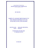
General Planar Location and
Green Arrangement Diagram
Design bases: 1. Code for Design of General Layout of Industrial
Enterprises (GB 50187-2012)
2. Code for Fire Protection Design of Buildings (GB 50016-2014)
3. Code for Design of Roads in Factories and Mines (GB J22-87)
4. Code for Design of Fire Protection for Thermal Power Plants and
Substations (GB 50229-2006)
5. Technical Code for Domestic waste Incinerating Treatment
Project (CJJ 90-2009)
6. Red line drawing of areas provided by Party A
Notes: 1. Dimensions in the drawing take the unit of the meter
2. Dimension indicated in the drawing is outside axis dimension of a
single building
3. Coordinate point indicated in the drawing is the coordinate of
cross point of outside axis of a single building
Chimney
Production
fire pool
Production
fire pool
Staff canteen
Dormitory
building
Integrated water
pump house
Cooling
tower
Provisional yard of
solidified fly ash
Pedestrian
brick/garden brick
Road
Elevation of new
building and
indoor terrace
Building firm
ground
Wall
Revetment
Planned red line
area
Parking space on
concrete pavement
General
drawing
Feasibility
Arbor/green land
Incineration and Power Generation Project of
Domestic Waste in Can Tho, Vietnam
General layout
Attached figure 4
(The original China GDE Engineering Co., Ltd.)