Sổ tay kết cấu thép - Section 10
Bạn đang xem bản rút gọn của tài liệu. Xem và tải ngay bản đầy đủ của tài liệu tại đây (320.34 KB, 46 trang )
10.1
SECTION 10
COLD-FORMED STEEL DESIGN
R. L. Brockenbrough, P.E.
President, R. L. Brockenbrough & Associates, Inc.,
Pittsburgh, Pennsylvania
This section presents information on the design of structural members that are cold-formed
to cross section shape from sheet steels. Cold-formed steel members include such products
as purlins and girts for the construction of metal buildings, studs and joists for light com-
mercial and residential construction, supports for curtain wall systems, formed deck for the
construction of floors and roofs, standing seam roof systems, and a myriad of other products.
These products have enjoyed significant growth in recent years and are frequently utilized
in some shape or form in many projects today. Attributes such as strength, light weight,
versatility, non-combustibility, and ease of production, make them cost effective in many
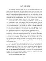
applications. Figure 10.1 shows cross sections of typical products.
10.1 DESIGN SPECIFICATIONS AND MATERIALS
Cold-formed members for most application are designed in accordance with the Specification
for the Design of Cold-Formed Steel Structural Members, American Iron and Steel Institute,
Washington, DC. Generally referred to as the AISI Specification, it applies to members cold-
formed to shape from carbon or low-alloy steel sheet, strip, plate, or bar, not more than 1-
in thick, used for load carrying purposes in buildings. With appropriate allowances, it can
be used for other applications as well. The vast majority of applications are in a thickness
range from about 0.014 to 0.25 in.
The design information presented in this section is based on the AISI Specification and
its Commentary, including revisions being processed. The design equations are written in
dimensionless form, except as noted, so that any consistent system of units can be used. A
synopsis of key design provisions is given in this section, but reference should be made to
the complete specification and commentary for a more complete understanding.
The AISI Specification lists all of the sheet and strip materials included in Table 1.6 (Art.
1.4) as applicable steels, as well several of the plate steels included in Table 1 (A36, A242,
A588, and A572). A283 and A529 plate steels are also included, as well as A500 structural
tubing (Table 1.7). Other steels can be used for structural members if they meet the ductility
requirements. The basic requirement is a ratio of tensile strength to yield stress not less than
1.08 and a total elongation of at least 10% in 2 in. If these requirements cannot be met,
alternative criteria related to local elongation may be applicable. In addition, certain steels
that do not meet the criteria, such as Grade 80 of A653 or Grade E of A611, can be used
10.2
SECTION TEN
FIGURE 10.1 Typical cold-formed steel members.
for multiple-web configurations (roofing, siding, decking, etc.) provided the yield stress is
taken as 75% of the specified minimum (or 60 ksi or 414 MPa, if less) and the tensile stress
is taken as 75% of the specified minimum (or 62 ksi or 428 MPa if less). Some exceptions
apply. Suitability can also be established by structural tests.
10.2 MANUFACTURING METHODS AND EFFECTS
As the name suggests, the cross section of a cold-formed member is achieved by a bending
operation at room temperature, rather than the hot rolling process used for the heavier struc-
tural steel shapes. The dominant cold forming process is known as roll-forming. In this
process, a coil of steel is fed through a series of rolls, each of which bends the sheet
progressively until the final shape is reached at the last roll stand. The number of roll stands
may vary from 6 to 20, depending upon the complexity of the shape. Because the steel is
fed in coil form, with successive coils weld-spliced as needed, the process can achieve speeds
up to about 300 ft/min and is well suited for quantity production. Small quantities may be
produced on a press-brake, particularly if the shape is simple, such as an angle or channel
cross section. In its simplest form, a press brake consists of a male die which presses the
steel sheet into a matching female die.
In general, the cold-forming operation is beneficial in that it increases the yield strength
of the material in the region of the bend. The flat material between bends may also show
an increase due to squeezing or stretching during roll forming. This increase in strength is
attributable to cold working and strain aging effects as discussed in Art. 1.10. The strength
increase, which may be small for sections with few bends, can be conservatively neglected.
Alternatively, subject to certain limitations, the AISI Specification includes provisions for
using a section-average design yield stress that includes the strength increase from cold-
forming. Either full section tension tests, full section stub column tests, or an analytical
method can be employed. Important parameters include the tensile-strength-to-yield-stress
COLD-FORMED STEEL DESIGN
10.3
TABLE 10.1
Safety Factors and Resistance Factors Adopted by the AISI Specification
Category
ASD
safety
factor,
⍀
LRFD
resistance
factor,
Tension members 1.67 0.95
Flexural members
(a) Bending strength
Sections with stiffened or partially stiffened compression flanges 1.67 0.95
Sections with unstiffened compression flanges 1.67 0.90
Laterally unbraced beams 1.67 0.90
Beams having one flange through-fastened to deck or sheathing (C- or Z-sections) 1.67 0.90
Beams having one flange fastened to a standing seam roof system 1.67 0.90
(b) Web design
Shear strength controlled by yielding (Condition a, Art. 10.12.4) 1.50 1.00
Shear strength controlled by buckling (Condition b or c, Art. 10.12.4) 1.67 0.90
Web crippling of single unreinforced webs 1.85 0.75
Web crippling of I-sections 2.00 0.80
Web crippling of two nested Z-sections 1.80 0.85
Stiffeners
(a) Transverse stiffeners 2.00 0.85
(b) Shear stiffeners 1.50 / 1.67 1.00 / 0.90
Concentrically loaded compression members 1.80 0.85
Combined axial load and bending
(a) Tension component 1.67 0.95
(b) Compression component 1.80 0.85
(c) Bending component 1.67 0.90 / 0.95
Cylindrical tubular members
(a) Bending 1.67 0.95
(b) Axial compression 1.80 0.85
Wall studs
(a) Compression 1.80 0.85
(b) Bending 1.67 0.90 / 0.95
Diaphragm construction 2.00 / 3.00 0.50 / 0.65
Welded connections
(a) Groove welds
Tension or compression 250 0.90
Shear, welds 2.50 0.80
Shear, base metal 2.50 0.90
(b) Arc spot welds
Shear, welds 2.50 0.60
Shear, connected part 2.50 0.50 / 0.60
Shear, minimum edge distance 2.50 0.60 / 0.70
Tension 2.50 0.60
(c) Arc seam welds
Shear, welds 2.50 0.60
Shear, connected part 2.50 0.60
(d) Fillet welds
Welds 2.50 0.60
Connected part, longitudinal loading
Weld length / sheet thickness
Ͻ
25 2.50 0.60
Weld length / sheet thickness
Ն
25 2.50 0.55
Connected part, transverse loading 2.50 0.60
10.4
SECTION TEN
TABLE 10.1
Safety Factors and Resistance Factors Adopted by the AISI Specification (Continued)
Category
ASD
safety
factor,
⍀
LRFD
resistance
factor,
(e) Flare groove welds
Welds 2.50 0.60
Connected part, longitudinal loading 2.50 0.55
Connected part, transverse loading 2.50 0.55
(f ) Resistance welds 2.50 0.65
Bolted connections
(a) Minimum spacing and edge distance*
When F
u
/ F
sy
Ն
1.08 2.00 0.70
When F
u
/ F
sy
Ͻ
1.08 2.22 0.60
(b) Tension strength on net section
With washers, double shear connection 2.00 0.65
With washers, single shear connection 2.22 0.55
Without washers, double or single shear 2.22 0.65
(c) Bearing strength 2.22 0.55 / 0.70
(d) Shear strength of bolts 2.40 0.65
(e) Tensile strength of bolts 2.00 / 2.25 0.75
Screw connections 3.00 0.50
* F
u
is tensile strength and F
sy
is yield stress.
ratio of the virgin steel and the radius-to-thickness ratio of the bends. The forming operation
may also induce residual stresses in the member but these effects are accounted for in the
equations for member design.
10.3 NOMINAL LOADS
The nominal loads for design should be according to the applicable code or specification
under which the structure is designed or as dictated by the conditions involved. In the absence
of a code or specification, the nominal loads should be those stipulated in the American
Society of Civil Engineers Standard, Minimum Design Loads for Buildings and Other Struc-
tures, ASCE 7. The following loads are used for the primary load combinations in the AISI
Specification:
D
ϭ
Dead load, which consists of the weight of the member itself, the weight of all
materials of construction incorporated into the building which are supported by the mem-
ber, including built-in partitions; and the weight of permanent equipment
E
ϭ
Earthquake load
L
ϭ
Live loads due to intended use and occupancy, including loads due to movable objects
and movable partitions and loads temporarily supported by the structure during mainte-
nance. (L includes any permissible load reductions. If resistance to impact loads is taken
into account in the design, such effects should be included with the live load.)
COLD-FORMED STEEL DESIGN
10.5
L
r
ϭ
Roof live load
S
ϭ
Snow load
R
r
ϭ
Rain load, except for ponding
W
ϭ
Wind load
The effects of other loads such as those due to ponding should be considered when signif-
icant. Also, unless a roof surface is provided with sufficient slope toward points of free
drainage or adequate individual drains to prevent the accumulation of rainwater, the roof
system should be investigated to assure stability under ponding conditions.
10.4 DESIGN METHODS
The AISI Specification is structured such that nominal strength equations are given for various
types of structural members such as beams and columns. For allowable stress design (ASD),
the nominal strength is divided by a safety factor and compared to the required strength
based on nominal loads. For Load and Resistance Factor Design (LRFD), the nominal
strength is multiplied by a resistance factor and compared to the required strength based on
factored loads. These procedures and pertinent load combinations to consider are set forth
in the specification as follows.
10.4.1 ASD Requirements
ASD Strength Requirements. A design satisfies the requirements of the AISI Specification
when the allowable design strength of each structural component equals or exceeds the
required strength, determined on the basis of the nominal loads, for all applicable load
combinations. This is expressed as
R
Յ
R /
⍀
(10.1)
n
where R
ϭ
required strength
R
n
ϭ
nominal strength (specified in Chapters B through E of the Specification)
⍀ ϭ
safety factor (see Table 10.1)
R
n
/
⍀ ϭ
allowable design strength
ASD Load Combinations. In the absence of an applicable code or specification or if the
applicable code or specification does not include ASD load combinations, the structure and
its components should be designed so that allowable design strengths equal or exceed the
effects of the nominal loads for each of the following load combinations:
1. D
2. D
ϩ
L
ϩ
(L
r
or S or R
r
)
3. D
ϩ
(W or E)
4. D
ϩ
L
ϩ
(L
r
or S or R
r
)
ϩ
(W or E )
Wind or Earthquake Loads for ASD. When the seismic load model specified by the
applicable code or specification is limit state based, the resulting earthquake load (E)is
permitted to be multiplied by 0.67. Additionally, when the specified load combinations in-
clude wind or earthquake loads, the resulting forces are permitted to be multiplied by 0.75.
However, no decrease in forces is permitted when designing diaphragms.
10.6
SECTION TEN
Composite Construction under ASD. For the composite construction of floors and roofs
using cold-formed deck, the combined effects of the weight of the deck, the weight of the
wet concrete, and construction loads (such as equipment, workmen, formwork) must be
considered.
10.4.2 LRFD Requirements
LRFD Strength Requirements. A design satisfies the requirements of the AISI Specification
when the design strength of each structural component equals or exceeds the required
strength determined on the basis of the nominal loads, multiplied by the appropriate load
factors, for all applicable load combinations. This is expressed as
R
Ͻ
R (10.2)
un
where R
u
ϭ
required strength
R
n
ϭ
nominal strength (specified in chapters B through E of the Specification)
ϭ
resistance factor (see Table 10.1)
R
n
ϭ
design strength
LRFD Load Factors and Load Combinations. In the absence of an applicable code or
specification, or if the applicable code or specification does not include LRFD load combi-
nations and load factors, the structure and its components should be designed so that design
strengths equal or exceed the effects of the factored nominal loads for each of the following
combinations:
1. 1.4D
ϩ
L
2. 1.2D
ϩ
1.6L
ϩ
0.5(L
r
or S or R
r
)
3. 1.2D
ϩ
1.6(L
r
or S or R
r
)
ϩ
(0.5L or 0.8W)
4. 1.2D
ϩ
1.3W
ϩ
0.5L
ϩ
0.5(L
r
or S or R
r
)
5. 1.2D
ϩ
1.5E
ϩ
0.5L
ϩ
0.2S
6. 0.9D
Ϫ
(1.3W or 1.5E)
Several exceptions apply:
1. The load factor for E in combinations (5) and (6) should equal 1.0 when the seismic load
model specified by the applicable code or specification is limit state based.
2. The load factor for L in combinations (3), (4), and (5) should equal 1.0 for garages, areas
occupied as places of public assembly, and all areas where the live load is greater than
100 psf.
3. For wind load on individual purlins, girts, wall panels and roof decks, multiply the load
factor for W by 0.9.
4. The load factor for L
r
in combination (3) should equal 1.4 in lieu of 1.6 when the roof
live load is due to the presence of workmen and materials during repair operations.
Composite Construction under LRFD. For the composite construction of floors and roofs
using cold-formed deck, the following additional load combination applies:
1.2D
ϩ
1.6C
ϩ
1.4C (10.3)
SW
where D
S
ϭ
weight of steel deck
C
W
ϭ
weight of wet concrete
C
ϭ
construction load (including equipment, workmen, and form work but excluding
wet concrete
COLD-FORMED STEEL DESIGN
10.7
10.5 SECTION PROPERTY CALCULATIONS
Because of the flexibility of the manufacturing method and the variety of shapes that can be
manufactured, properties of cold-formed sections often must be calculated for a particular
configuration of interest rather than relying on tables of standard values. However, properties
of representative or typical sections are listed in the Cold-Formed Steel Design Manual,
American Iron and Steel Institute, 1996, Washington, DC (AISI Manual).
Because the cross section of a cold-formed section is generally of a single thickness of
steel, computation of section properties may be simplified by using the linear method. With
this method, the material is considered concentrated along the centerline of the steel sheet
and area elements are replaced by straight or curved line elements. Section properties are
calculated for the assembly of line elements and then multiplied by the thickness, t. Thus,
the cross section area is given by A
ϭ
L
ϫ
t, where L is the total length of all line elements;
the moment of inertia of the section is given by I
ϭ
I
Ј ϫ
t, where I
Ј
is the moment of
inertia determined for the line elements; and the section modulus is calculated by dividing
I by the distance from the neutral axis to the extreme fiber, not to the centerline of the
extreme element. As subsequently discussed, it is sometimes necessary to use a reduced or
effective width rather than the full width of an element.
Most sections can be divided into straight lines and circular arcs. The moments of inertia
and centroid location of such elements are defined by equations from fundamental theory as
presented in Table 10.2.
10.6 EFFECTIVE WIDTH CONCEPT
The design of cold-formed steel differs from heavier construction in that elements of mem-
bers typically have large width-to-thickness (w / t) ratios and are thus subject to local buck-
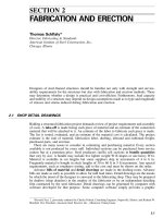
ling. Figure 10.2 illustrates local buckling in beams and columns. Flat elements in com-
pression that have both edges parallel to the direction of stress stiffened by a web, flange,
lip or stiffener are referred to as stiffened elements. Examples in Fig. 10.2 include the top
flange of the channel and the flanges of the I-cross section column.
To account for the effect of local buckling in design, the concept of effective width is
employed for elements in compression. The background for this concept can be explained
as follows.
Unlike a column, a plate does not usually attain its maximum load carrying capacity at
the buckling load, but usually shows significant post buckling strength. This behavior is
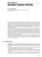
illustrated in Fig. 10.3, where longitudinal and transverse bars represent a plate that is simply
supported along all edges. As the uniformly distributed end load is gradually increased, the
longitudinal bars are equally stressed and reach their buckling load simultaneously. However,
as the longitudinal bars buckle, the transverse bars develop tension in restraining the lateral
deflection of the longitudinal bars. Thus, the longitudinal bars do not collapse when they
reach their buckling load but are able to carry additional load because of the transverse
restraint. The longitudinal bars nearest the center can deflect more than the bars near the
edge, and therefore, the edge bars carry higher loads after buckling than do the center bars.
The post buckling behavior of a simply supported plate is similar to that of the grid
model. However, the ability of a plate to resist shear strains that develop during buckling
also contributes to its post buckling strength. Although the grid shown in Fig. 10.3a buckled
into only one longitudinal half-wave, a longer plate may buckle into several waves as illus-
trated in Figs. 10.2 and 10.3b. For long plates, the half-wave length approaches the width
b.
After a simply supported plate buckles, the compressive stress will vary from a maximum
near the supported edges to a minimum at the mid-width of the plate as shown by line 1 of
10.8
SECTION TEN
TABLE 10.2
Moment of Inertia for Line Elements
Source: Adapted from Cold-Formed Steel Design Manual, American Iron and Steel Institute, 1996,
Washington, DC.
COLD-FORMED STEEL DESIGN
10.9
FIGURE 10.2 Local buckling of compression elements. (a) In beams; (b)in
columns. (Source: Commentary on the Specification for the Design of Cold-
Formed Steel Structural Members, American Iron and Steel Institute, Washington,
DC, 1996, with permission.)
Fig. 10.3c. As the load is increased the edge stresses will increase, but the stress in the mid-
width of the plate may decrease slightly. The maximum load is reached and collapse is
initiated when the edge stress reaches the yield stress—a condition indicated by line 2 of
Fig. 10.3c.
The post buckling strength of a plate element can be considered by assuming that after
buckling, the total load is carried by strips adjacent to the supported edges which are at a
uniform stress equal to the actual maximum edge stress. These strips are indicated by the
dashed lines in Fig. 10.3c. The total width of the strips, which represents the effective width
of the element b, is defined so that the product of b and the maximum edge stress equals
the actual stresses integrated over the entire width. The effective width decreases as the
applied stress increases. At maximum load, the stress on the effective width is the yield
stress.
Thus, an element with a small enough w/t will be able to reach the yield point and will
be fully effective. Elements with larger ratios will have an effective width that is less than
the full width, and that reduced width will be used in section property calculations.
The behavior of elements with other edge-support conditions is generally similar to that
discussed above. However, an element supported along only one edge will develop only one
effective strip.
Equations for calculating effective widths of elements are given in subsequent articles
based on the AISI Specification. These equations are based on theoretical elastic buckling
theory but modified to reflect the results of extensive physical testing.
10.10
SECTION TEN
FIGURE 10.3 Effective width concept. (a) Buckling of grid model; (b) buckling of
plate; (c) stress distributions.
COLD-FORMED STEEL DESIGN
10.11
10.7 MAXIMUM WIDTH-TO-THICKNESS RATIOS
The AISI Specification gives certain maximum width-to-thickness ratios that must be adhered
to.
For flange elements, such as in flexural members or columns, the maximum flat width-
to-thickness ratio, w/t, disregarding any intermediate stiffeners, is as follows:
Stiffened compression element having one longitudinal edge connected to a web or flange
element, the other stiffened by
(a) a simple lip, 60
(b) other stiffener with I
S
Ͻ
I
a
,90
(c) other stiffener with I
S
Ն
I
a
,90
Stiffened compression element with both longitudinal edges connected to other stiffened
elements, 500
Unstiffened compression element, 60
In the above, I
S
is the moment of inertia of the stiffener about its centroidal axis, parallel to
the element to be stiffened, and I
a
is the moment of inertia of a stiffener adequate for the
element to behave as a stiffened element. Note that, although greater ratios are permitted,
stiffened compression elements with w / t
Ͼ
250, and unstiffened compression elements with
w/t
Ͼ
30 are likely to develop noticeable deformations at full design strength, but ability to
develop required strength will be unaffected.
For web elements of flexural members, the maximum web depth-to-thickness ratio, h/t,
disregarding any intermediate stiffeners, is as follows:
Unreinforced webs, 200
Webs with qualified transverse stiffeners that include (a) bearing stiffeners only, 260
(b) bearing and intermediate stiffeners, 300
10.8 EFFECTIVE WIDTHS OF STIFFENED ELEMENTS
10.8.1 Uniformly Compressed Stiffened Elements
The effective width for load capacity determination depends on a slenderness factor
defined
as
1.052 w ƒ
ϭ
(10.4)
ͩͪ
Ί
tE
͙
k
where k
ϭ
plate buckling coefficient (4.0 for stiffened elements supported by a web along
each longitudinal edge; values for other conditions are given subsequently)
ƒ
ϭ
maximum compressive stress (with no safety factor applied)
E
ϭ
Modulus of elasticity (29,500 ksi or 203 000 MPa)
10.12
SECTION TEN
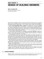
FIGURE 10.4 Illustration of uniformly compressed stiffened element. (a) Actual element; (b) stress on
effective element. (Source: Specification for the Design of Cold-Formed Steel Structural Members, Amer-
ican Iron and Steel Institute, Washington, DC, 1996, with permission.)
For flexural members, when initial yielding is in compression, ƒ
ϭ
F
y
, where F
y
is the yield
stress; when the initial yielding is in tension, ƒ
ϭ
the compressive stress determined on the
basis of effective section. For compression members, ƒ
ϭ
column buckling stress.
The effective width is as follows:
when
Յ
0.673, b
ϭ
w (10.5)
when
Ͼ
0.673, b
ϭ
w (10.6)
where the reduction factor
is defined as
ϭ
(1
Ϫ
0.22/
)/
(10.7)
Figure 10.4 shows the location of the effective width on the cross section, with one-half
located adjacent to each edge.
Effective widths determined in this manner, based on maximum stresses (no safety factor)
define the cross section used to calculate section properties for strength determination. How-
ever, at service load levels, the effective widths will be greater because the stresses are
smaller, and another set of section properties should be calculated. Therefore, to calculate
effective width for deflection determination, use the above equations but in Eq. 10.4, sub-
stitute the compressive stress at design loads, ƒ
d
.
10.8.2 Stiffened Elements with Stress Gradient
Elements with stress gradients include webs subjected to compression from bending alone
or from a combination of bending and uniform compression. For load capacity determination,
the effective widths b
1
and b
2
illustrated in Fig. 10.5 must be determined. First, calculate
the ratio of stresses
ϭ
ƒ /ƒ (10.8)
21
where ƒ
1
and ƒ
2
are the stresses as shown, calculated on the basis of effective section, with
no safety factor applied. In this case ƒ
1
is compression and treated as
ϩ
, while ƒ
2
can be
either tension (
Ϫ
) or compression (
ϩ
). Next, calculate the effective width, b
e
,asifthe
element was in uniform compression (Art. 10.8.1) using ƒ
1
for ƒ and with k determined as
follows:
3
k
ϭ
4
ϩ
2(1
Ϫ
)
ϩ
2(1
Ϫ
) (10.9)
Effective widths b
1
and b
2
are determined from the following equations:
COLD-FORMED STEEL DESIGN
10.13
FIGURE 10.5 Illustration of stiffened element with stress gradient. (a) Actual element; (b) stress on ef-
fective element varying from compression to tension; (c) stress on effective element with non-uniform com-
pression. (Source: Specification for the Design of Cold-Formed Steel Structural Members, American Iron
and Steel Institute, Washington, DC, 1996, with permission.)
b
ϭ
b /(3
Ϫ
) (10.10)
1 e
b
ϭ
b / 2 (10.11)
2 e
The sum of b
1
and b
2
must not exceed the width of the compression portion of the web
calculated on the basis of effective section.
Effective width for deflection determination is calculated in the same manner except that
stresses are calculated at service load levels based on the effective section at that load.
10.14
SECTION TEN
FIGURE 10.6 Illustration of uniformly compressed unstiffened element. (a) Actual element; (b) stress
on effective element. (Source: Specification for the Design of Cold-Formed Steel Structural Members,
American Iron and Steel Institute, Washington, DC, 1996, with permission.)
10.9 EFFECTIVE WIDTHS OF UNSTIFFENED ELEMENTS
10.9.1 Uniformly Compressed Unstiffened Elements
The effective widths for uniformly compressed unstiffened elements are calculated in the
same manner as for stiffened elements (Art. 10.8.1), except that k in Eq. 10.4 is taken as
0.43. Figure 10.6 illustrates the location of the effective width on the cross section.
10.9.2 Unstiffened Elements and Edge Stiffeners with Stress Gradient
The effective width for unstiffened elements (including edge stiffeners) with a stress gradient
is calculated in the same manner as for uniformly loaded stiffened elements (Art. 10.9.1)
except that (1) k in Eq. 10.4 is taken as 0.43, and (2) the stress ƒ
3
is taken as the maximum
compressive stress in the element. Figure 10.7 shows the location of ƒ
3
and the effective
width for an edge stiffener consisting of an inclined lip. (Such lips are more structurally
efficient when bent at 90
Њ
, but inclined lips allow nesting of certain sections.)
10.10 EFFECTIVE WIDTHS OF UNIFORMLY COMPRESSED
ELEMENTS WITH EDGE STIFFENER
A commonly encountered condition is a flange with one edge stiffened by a web, the other
by an edge stiffener (Fig. 10.7). To determine its effective width for load capacity determi-
nation, one of three cases must be considered. The case selection depends on the relation
between the flange flat width-to-thickness ratio, w/t, and the parameter S defined as
S
ϭ
1.28
͙
E/ƒ (10.12)
For each case an equation will be given for determining I
a
, the moment of inertia required
for a stiffener adequate so that the flange element behaves as a stiffened element, I
S
is the
moment of inertia of the full section of the stiffener about its centroidal axis, parallel to the
element to be stiffened. A
Ј
S
is the effective area of a stiffener of any shape, calculated by
methods previously discussed. The reduced area of the stiffener to be used in section property
calculations is termed A
S
and its relation to A
Ј
S
is given for each case. Note that for edge
stiffeners, the rounded corner between the stiffener and the flange is not considered as part
of the stiffener in calculations. The following additional definitions for a simple lip stiffener
illustrated in Fig. 10.7 apply. The effective width d
S
Ј
is that of the stiffener calculated ac-
cording to Arts. 10.9.1 and 10.9.2. The reduced effective width to be used in section property
COLD-FORMED STEEL DESIGN
10.15
FIGURE 10.7 Illustration of element with edge stiffener. (a) Actual element; (b) stress on effective element and
stiffener. (Source: Specification for the Design of Cold-Formed Steel Structural Members, American Iron and Steel
Institute, Washington, DC 1996, with permission.)
calculations is termed d
S
and its relation to d
S
Ј
is given for each case. For the inclined stiffener
of flat depth d at an angle
as shown in Fig. 10.7,
32
I
ϭ
(dtsin
)/12 (10.13)
S
A
Ј ϭ
d
Ј
t (10.14)
SS
Limit d/t to 14.
Case I: w/ t
Յ
S/3
For this condition, the flange element is fully effective without an edge stiffener so b
ϭ
w, I
a
ϭ
0, d
S
ϭ
d
S
Ј
, A
S
ϭ
A
Ј
S
.
Case II: S/3
Ͻ
w/t
Ͻ
S
43
I
ϭ
399t {[(w/t)/S]
Ϫ ͙
k /4} (10.15)
au
where k
u
ϭ
0.43. The effective width b is calculated according to Art. 10.8.1 using the
following k:
10.16
SECTION TEN
n
k
ϭ
C (k
Ϫ
k )
ϩ
k (10.16)
2 au u
where n
ϭ
1/2, C
2
ϭ
I
S
/I
a
, and C
1
ϭ
2
Ϫ
C
2
. The coefficients C
1
and C
2
give the proportion
of the effective width to be placed along either edge of the flange, Fig. 10.7. The plate
buckling coefficient k
a
and other terms are determined as follows:
For a simple lip stiffener with 140
ЊՆ
Ն
40
Њ
and D / w
Յ
0.8 (see Fig. 10.7),
k
ϭ
5.25
Ϫ
5(D/w)
Յ
4.0 (10.17)
a
d
ϭ
Cd
Ј
(10.18)
S 2 S
For other stiffeners,
k
ϭ
4.0 (10.19)
a
A
ϭ
CA
Ј
(10.20)
S 2 S
Case III: w/t
Ն
S
4
I
ϭ
t {[115(w/t)/S]
ϩ
5} (10.21)
a
The following are calculated as for Case II, but with n
ϭ
1/3: C
1
, C
2
, b, k, d
S
, and A
S
.
For all cases, effective width for deflection determination is calculated in the same manner
except that stresses are calculated at service load levels based on the effective section at that
load.
10.11 TENSION MEMBERS
The nominal tensile strength, T
n
, of an axial loaded tension member is the smallest of three
limit states: (1) yielding in the gross section, Eq. 10.22; (2) fracture in the net section away
from the connections, Eq. 10.23; and (3) fracture in the net section at connections (Art.
10.18.2)
T
ϭ
AF (10.22)
ngy
T
ϭ
AF (10.23)
nnu
where A
g
is the gross cross section area, A
n
is the net cross section area, F
y
is the design
yield stress and F
u
is the tensile strength.
As with all of the member design provisions, these nominal strengths must be divided
by a safety factor,
⍀
, for ASD (Art. 10.4.1) or multiplied by a resistance factor,
,for
LRFD (Art. 10.4.2). See Table 10.1 for
⍀
and
values for the appropriate member or
connection category.
10.12 FLEXURAL MEMBERS
In the design of flexural members consideration must be given to bending strength, shear
strength, and web crippling, as well as combinations thereof, as discussed in subsequent
articles. Bending strength must consider both yielding and lateral stability. In some appli-
cations, deflections are also an important consideration.
COLD-FORMED STEEL DESIGN
10.17
10.12.1 Nominal Strength Based on Initiation of Yielding
For a fully braced member, the nominal strength, M
n
, is the effective yield moment based
on section strength:
M
ϭ
SF (10.24)
ney
where S
e
is the elastic section modulus of the effective section calculated with the extreme
fiber at the design yield stress, F
y
. The stress in the extreme fiber can be compression or
tension depending upon which is farthest from the neutral axis of the effective section. If
the extreme fiber stress is compression, the effective width (Art. 10.8–10.10) and the effective
section can be calculated directly based on the stress F
y
in that compression element. How-
ever, if the extreme fiber stress is tension, the stress in the compression element depends on
the effective section and, therefore, a trial and error solution is required (Art. 10.22).
10.12.2 Nominal Strength Based on Lateral Buckling
For this condition, the nominal strength, M
n
, of laterally unbraced segments of singly-, dou-
bly-, and point-symmetric sections is given by Eq. 10.25. These provisions apply to I-, Z-,
C-, and other singly-symmetric sections, but not to multiple-web decks, U- and box sections.
Also, beams with one flange fastened to deck, sheathing, or standing seam roof systems are
treated separately. The nominal strength is
M
ϭ
SM/S (10.25)
nccƒ
where S
ƒ
ϭ
Elastic section modulus of the full unreduced section for the extreme compres-
sion fiber
S
c
ϭ
Elastic section modulus of the effective section calculated at a stress M
c
/S
ƒ
in
the extreme compression fiber
M
c
ϭ
Critical moment calculated as follows:
For M
e
Ն
2.78 M
y
M
ϭ
M (10.26)
cy
For 2.78 M
y
Ͼ
M
e
Ͼ
0.56M
y
10M
10
y
M
ϭ
M 1
Ϫ
(10.27)
ͩͪ
cy
936M
e
For M
e
Յ
0.56M
y
M
ϭ
M (10.28)
ce
where M
y
ϭ
Moment causing initial yield at the extreme compression fiber of the full section
ϭ
S
ƒ
F
y
M
e
ϭ
Elastic critical moment calculated according to (a) or (b) below:
(a) For singly-, doubly-, and point symmetric sections:
M
ϭ
CrA
͙
for bending about the symmetry axis. (10.29)
ebo eyt
10.18
SECTION TEN
For singly-symmetric sections, x-axis is the axis of symmetry oriented such
that the shear center has a negative x-coordinate. For point-symmetric sec-
tions, use 0.5 M
e
.
Alternatively, M
e
can be calculated using the equation for doubly-symmetric
I-sections or point-symmetric sections given in (b).
M
e
ϭ
C
s
A
ex
[j
ϩ
C
s
]/C
TF
for bending (10.30)
22
͙
j
ϩ
r (
/
)
otex
about the centroidal axis perpendicular to the symmetry axis for singly-
symmetric sections only
C
s
ϭϩ
1 for moment causing compression on the shear center side of the centroid
C
s
ϭϪ
1 for moment causing tension on the shear center side of the centroid
ex
ϭ
2
E
2
(KL/r )
xx x
(10.31)
ey
ϭ
2
E
2
(KL/r )
yy y
(10.32)
t
ϭ
2
1
EC
w
GJ
ϩ
ͫͬ
22
Ar (KL)
ott
(10.33)
A
ϭ
Full cross-sectional area
C
b
ϭ
12.5M
max
2.5M
ϩ
3M
ϩ
4M
ϩ
3M
max A B C
(10.34)
where M
max
ϭ
absolute value of maximum moment in the unbraced segment
M
A
ϭ
absolute value of moment at quarter point of unbraced segment
M
B
ϭ
absolute value of moment at centerline of unbraced segment
M
C
ϭ
absolute value of moment at three-quarter point of unbraced segment C
b
is
permitted to be conservatively taken as unity for all cases.
For cantilevers or overhangs where the free end is unbraced, C
b
ϭ
1.0. For
members subject to combined compressive axial load and bending moment
(Art. 10.15), C
b
ϭ
1.0.
E
ϭ
Modulus of elasticity
C
TF
ϭ
0.6
Ϫ
0.4 (M
1
/M
2
) (10.35)
where
M
1
is the smaller and M
2
the larger bending moment at the ends of the
unbraced length in the plane of bending, and where M
1
/M
2
, the ratio of end
moments, is positive when M
1
and M
2
have the same sign (reverse curvature
bending) and negative when they are of opposite sign (single curvature bend-
ing). When the bending moment at any point within an unbraced length is
larger than that at both ends of this length, and for members subject to com-
bined compressive axial load and bending moment (Art. 10.15), C
TF
ϭ
1.0.
r
o
ϭ
Polar radius of gyration of the cross section about the shear center
r
o
ϭ
(10.36)
22 2
͙
r
ϩ
r
ϩ
x
xyo
r
x
, r
y
ϭ
Radii of gyration of the cross section about the centroidal principal axes
G
ϭ
Shear modulus (11,000 ksi or 78 000 MPa)
K
x
, K
y
, K
t
ϭ
Effective length factors for bending about the x- and y-axes, and for twisting
L
x
, L
y
, L
t
ϭ
Unbraced length of compression member for bending about the x- and y-axes,
and for twisting
x
o
ϭ
Distance from the shear center to the centroid along the principal x-axis, taken
as negative
J
ϭ
St. Venant torsion constant of the cross section
C
w
ϭ
Torsional warping constant of the cross section