Newnes, interfacing PIC microcontrollers (2006) 0750680288
Bạn đang xem bản rút gọn của tài liệu. Xem và tải ngay bản đầy đủ của tài liệu tại đây (4.19 MB, 313 trang )
Else_IPM-BATES_fm.qxd
7/20/2006
11:52 AM
Page i
Interfacing PIC Microcontrollers
Embedded Design by Interactive Simulation
i
This page intentionally left blank
ii
Else_IPM-BATES_fm.qxd
7/20/2006
11:52 AM
Page iii
Interfacing PIC Microcontrollers
Embedded Design by Interactive Simulation
Martin Bates
Amsterdam ● Boston ● Heidelberg ● London ● New York ● Oxford
Paris ● San Diego ● San Francisco ● Singapore ● Sydney ● Tokyo
Newnes is an imprint of Elsevier
iii
Else_IPM-BATES_fm.qxd
7/20/2006
11:52 AM
Page iv
Newnes is an imprint of Elsevier
Linacre House, Jordan Hill, Oxford OX2 8DP, UK
The Boulevard, Langford Lane, Kidlington, Oxford OX5 1GB, UK
84 Theobald's Road, London WC1X 8RR, UK
Radarweg 29, PO Box 211, 1000 AE Amsterdam, The Netherlands
30 Corporate Drive, Suite 400, Burlington, MA 01803, USA
525 B Street, Suite 1900, San Diego, CA 92101-4495, USA
Copyright © 2006, Martin Bates. Published by Elsevier 2006. All rights reserved
The right of Author Name to be identified as the author of this work has been
asserted in accordance with the Copyright, Designs and Patents Act 1988
No part of this publication may be reproduced, stored in a retrieval system
or transmitted in any form or by any means electronic, mechanical, photocopying,
recording or otherwise without the prior written permission of the publisher
Permissions may be sought directly from Elsevier's Science & Technology Rights
Department in Oxford, UK: phone (+44) (0) 1865 843830; fax (+44) (0) 1865 853333;
email: Alternatively you can submit your request online by
visiting the Elsevier web site at and selecting
Obtaining permission to use Elsevier material
British Library Cataloguing in Publication Data
A catalogue record for this book is available from the British Library
Library of Congress Cataloging-in-Publication Data
A catalog record for this book is available from the Library of Congress
For information on all Newnes publications
visit our web site at books.elsevier.com
Printed and bound in Great Britain
06 07 08 09 10 10 9 8 7 6 5 4 3 2 1
ISBN-13: 978-0-7506-8028-8
ISBN-10: 0-7506-80288-8
iv
Else_IPM-BATES_fm.qxd
7/20/2006
11:52 AM
Page v
Preface
I have my students to thank for this book. Regardless of ability, each has had
a role to play. The more able students have always helped, through their project work, to develop new ideas and solutions in electronic design. Some have
displayed an astonishing instinctive understanding of engineering ideas, and
some have been so keen to learn as to make teaching easy and rewarding.
There is never enough time to give each individual student the time and help
they deserve. So, one has to start writing to make sure that the essential technical information is at least accessible, and hope that students are able to make
best use of it.
Another spur to writing this book has been the development of the interactive design software which has made the job of learning and teaching electronics that much more enjoyable. The Proteus software used in this book has
been developed by a talented team at Labcenter Electronics in the UK, led by
John Jameson and Iain Cliffe. They have a world beating product, and I wanted
to make a small contribution to encouraging students and engineers to use it.
It allows us to bring electronic circuits to life on the computer screen instantly.
It has always been a problem in electronics that you cannot see a circuit
working in the same way that a mechanical engineer can see a steam engine
pumping up and down. Sure, we can see the screen flickering on a television,
or an electric motor spinning, but you cannot see electrons or volts. As a result, it has always been that much more difficult to teach electronics. Proteus
is a big step towards bringing electronics alive, as such it helps us to participate more effectively in the communications and information revolution that is
all around us.
v
This page intentionally left blank
vi
Else_IPM-BATES_fm.qxd
7/20/2006
11:52 AM
Page vii
Introduction
This book is a sequel to my first effort ‘PIC Microcontrollers, an Introduction
to Microelectronics’. This attempted to provide a comprehensive introduction
to the subject via a single type of microcontroller, which is essentially a complete computer on a chip. The PIC was the first widely available device to use
flash memory, which makes it ideal for experimental work. Flash memory allows the program to be replaced quickly and easily with a new version. It is
now commonplace, not least in our USB memory sticks, but also in a wide
range of electronic systems where user data need to be retained during power
down. Cheap flash memory microcontrollers have transformed the teaching of
microelectronics – they are re-usable and the internal architecture is fixed,
making them easier to explain. On the other hand, beginners can ignore the
innards and treat them as a black box, and get on with the programming! The
small instruction set of the PIC is also a major advantage – only 35 instructions to learn. Compare that with a complex processor such as the Pentium,
which is quite terrifying compared with the PIC! The quality of the PIC technical documentation is also a major factor.
For these reasons, I set out to introduce the PIC into my teaching as widely as
possible. At the same time, schools, universities and hobbyists were starting to use
it, so continuity of learning was possible. Since there is never enough time to
teach all the detail, I decided to set out a full description of the basic PIC device,
the 16F84, and some representative applications. Although this particular chip is
now redundant in terms of new products, the basic architecture is unchanged in
current chips, so it is still a useful starting point.
My students and I soon graduated to the more powerful PIC 16F877. This is
now used widely as a more advanced teaching device, because it has a full
complement of interfaces: analogue input, serial ports, slave port and so on,
plus a good range of hardware timers. A full description of this chip covers
most of the features that higher level students need for project work with microcontrollers.
When interactive simulation of microcontrollers became available, a new dimension was added. We could now see them in action without having to spend
a lot of time building and debugging hardware! These design tools allow even
vii
Else_IPM-BATES_fm.qxd
7/20/2006
11:52 AM
Page viii
Introduction
the inexperienced designer to create a working system relatively quickly. As a
result, my next step was to document the 16F877 and its applications, through
the medium of interactive simulation.
Proteus© from Labcenter Electronics© consists of two main parts, ISIS and
ARES. ARES is a layout package, which is used to create a PCB when the circuit has been designed. ISIS is the schematic capture and interactive simulation software used to create the circuit drawing and to test the circuit prior to
building the real hardware. SPICE is a mathematical circuit modelling system
which has been developed over many years – these models can now be used to
bring the drawing to life. Onscreen buttons and virtual signal sources, for
example, provide inputs to the circuit. Output can be displayed on a voltage
probe or on a virtual oscilloscope. Now that we have microcontroller simulation as well, we really are in business. The MCU can be dropped on the screen,
a program attached and debugged instantly. Electronic design has never been
so easy!
It is assumed that the reader is familiar with the basics of microcontroller systems, as covered in the first book. This one follows on, and is divided into three
main parts. In the first part, the 16F877 hardware and programming and the
simulation system are introduced. In the second part, a range of interfacing
techniques are covered; switches, keypads, displays, digital and analogue interfacing, data conversion and so on. In the third part, power outputs, serial interfaces, sensors, and system design examples culminate in a design for a general
purpose board which provides a platform for further development.
Each topic is illustrated by designs based on the 16F877, so that the reader
can concentrate on the interfacing and not have to deal with different microcontrollers. All the circuits are available on the associated website (see links
below). All schematics were produced using ISIS – and you can produce them
to the same standard in your own reports. The designs can be downloaded and
run along side the book. ISIS Lite, the introductory design package, can be
downloaded free, with extra features available for a small registration fee. The
16F877 will simulate fully, and the software changed, but the hardware cannot
be modified unless a licence is purchased for this device. The microcontroller
models can be purchased for institution or professional use in packages – see
the Labcenter website.
Get PICing!
viii
Else_IPM-BATES_fm.qxd
7/20/2006
11:52 AM
Page ix
Links, References and Acknowledgements
Support Website
www.picmicros.org.uk
This book is supported by the above website created by the author to provide
•
•
•
•
•
application examples for downloading, listed by chapter
applications to be displayed on screen for teaching purposes
easy access to relevant data sheets
links to relevant manufacturers websites, Microchip and Labcenter
links to 'PIC Microcontrollers - an Introduction to Microelectronic Systems'
If you have Proteus Professional installed and a licence for the PIC 16 series
microcontrollers, you will be able to modify the hardware and application program to your own requirements.
If not, Labcenter have agreed a special offer for readers of this book: a special
low cost edition of ISIS Lite schematic capture, with PROSPICE Lite simulation tools and PIC 16F877 licence. A key will be e-mailed to you which will
allow the demo programs to be fully tested and modified.
If you do not have a licensed copy of Proteus, you can download the demo version and run the applications and modify the code, but not the hardware.
Please log on to www.picmicros.org.uk for details; also visit www.labcenter.co.uk
and www.proteuslite.com for Proteus/ISIS information and downloads.
ix
Else_IPM-BATES_fm.qxd
7/20/2006
11:52 AM
Page x
Links, References and Acknowledgements
Labcenter Electronics
www.labcenter.co.uk
Manufacturer and supplier of Proteus VSM electronic design system
Microchip Technology Inc.
www.microchip.com
Manufacturer of the PIC microcontroller range and MPLAB IDE
Custom Computer Services, Inc.
www.ccsinfo.com
Manufacturer and supplier of PIC CCS ‘C’ Compilers
Data References and Trademark Acknowledgements
Microchip Technology Inc., RS Components, Fairchild, Intel,
Freescale (Motorola), National Semiconductor, Sensor Technics,
Densitron, Honeywell, SGS Thomson, Maxim, ST Microelectronics,
HBM, ARM, AVR Atmel, Texas, Vishay.
I would also like to thank the dedicated teachers of engineering that I have
worked with, especially Melvyn Ball at Hastings College and Chris Garrett at the
University of Brighton, and, of course, Julia Bates.
Martin Bates
Hastings, UK
x
Else_IPM-BATES_fm.qxd
7/20/2006
11:52 AM
Page xi
Contents
Part 1 Microcontroller
1 PIC Hardware
1
3
Processor System
4
PIC 16F877 Architecture
8
PIC Instruction Set
18
Special Function Registers
25
2 PIC Software
35
Assembly Language
37
Software Design
44
‘C’ Programming
47
3 Circuit Simulation
55
Basic Circuit
56
Software Debugging
63
Hardware Testing
65
Hardware Implementation
70
Program Downloading
73
xi
Else_IPM-BATES_fm.qxd
7/20/2006
11:52 AM
Page xii
Contents
Part 2
Interfacing
77
4
Input & Output
79
Switch Input
79
Switch Debouncing
81
Timer and Interrupts
84
Keypad Input
87
7-Segment LED Display
88
Liquid Crystal Display
90
5
6
7
xii
Data Processing
101
Number Systems
101
Conversion
106
Variable Types
110
Arithmetic
112
Calculate, Compare & Capture
121
Calculator
121
Pulse Output
128
Period Measurement
130
Analogue Interfacing
141
8-bit Conversion
141
10-bit Conversion
145
Amplifier Interfaces
149
Else_IPM-BATES_fm.qxd
7/20/2006
11:52 AM
Page xiii
Contents
Transient & Frequency Response
160
Instrumentation Amplifier
161
Current Loop
163
Comparators
165
Op-amp Selection
168
Analogue Output
168
Part 3 Systems
177
8 Power Outputs
179
Current Drivers
179
Relays & Motors
183
Power Output Interfacing
185
Motor Interfacing
189
9 Serial Communication
201
USART
201
SPI
205
I2C
210
10 Sensor Interfacing
223
Sensors
223
Sensor Types
228
Amplifier Design
236
Weather Station
238
xiii
Else_IPM-BATES_fm.qxd
7/20/2006
11:52 AM
Page xiv
Contents
xiv
11 System Design
249
Base System
249
Memory System
259
Other PIC Chips
266
System Design
270
Other MCU Families
274
Answers to Assessment Questions
279
Index & Abbreviations
291
Else_IPM-BATES_ch001.qxd
6/27/2006
10:04 PM
Page 1
Part 1
Microcontroller
1
This page intentionally left blank
2
Else_IPM-BATES_ch001.qxd
6/27/2006
10:04 PM
Page 3
1
PIC Hardware
The microcontroller is simply a computer on a chip. It is one of the most
important developments in electronics since the invention of the microprocessor
itself. It is essential for the operation of devices such as mobile phones, DVD
players, video cameras, and most self-contained electronic systems. The small
LCD screen is a good clue to the presence of an MCU (Microcontroller Unit) –
it needs a programmed device to control it. Working sometimes with other
chips, but often on its own, the MCU provides the key element in the vast
range of small, programmed devices which are now commonplace.
Although small, microcontrollers are complex, and we have to look carefully
at the way the hardware and software (control program) work together to
understand the processes at work. This book will show how to connect the popular PIC range of microcontrollers to the outside world, and put them to work.
To keep things simple, we will concentrate on just one device, the PIC 16F877,
which has a good range of features and allows most of the essential techniques
to be explained. It has a set of serial ports built in, which are used to transfer data
to and from other devices, as well as analogue inputs, which allow measurement
of inputs such as temperature. All standard types of microcontrollers work in a
similar way, so analysis of one will make it possible to understand all the others.
The PIC 16F877 is also a good choice for learning about micro-controllers,
because the programming language is relatively simple, as compared with a
microprocessor such as the Intel Pentium™, which is used in the PC. This has
a powerful, but complex, instruction set to support advanced multimedia
applications. The supporting documentation for the PIC MCU is well designed,
3
Else_IPM-BATES_ch001.qxd
6/27/2006
10:04 PM
Page 4
Interfacing PIC Microcontrollers
and a development system, for writing and testing programs, can be downloaded free from the Microchip website (www.microchip.com).
Processor System
The microcontroller contains the same main elements as any computer system:
• Processor
• Memory
• Input/Output
In a PC, these are provided as separate chips, linked together via bus connections on a printed circuit board, but under the control of the microprocessor
(CPU). A bus is a set of lines which carry data in parallel form which are
shared by the peripheral devices. The system can be designed to suit a particular application, with the type of CPU, size of memory and selection of
input/output (I/O) devices tailored to the system requirements.
In the microcontroller, all these elements are on one chip. This means that
the MCU for a particular application must be chosen from the available range
to suit the requirements. In any given circuit, the microcontroller also tends to
have a single dedicated function (in contrast to the PC); this type of system is
described as an embedded application (Figure 1.1).
Processor
In a microprocessor system or a microcontroller, a single processor block is in
charge of all input, output, calculations and control. This cannot operate
without a program, which is a list of instructions that is held in memory. The
CPU
Output
Input
Memory
Figure 1.1 Block diagram of a basic microprocessor system
4
Else_IPM-BATES_ch001.qxd
6/27/2006
10:04 PM
Page 5
PIC Hardware
CPU
Program Memory
Address
0000
0001
0002
0003
0004
0005
0006
etc
Instruction
10010011
01010001
10000100
00011001
01011100
xxxxxxxx
xxxxxxxx
etc
Address bus
Data bus
Program
Counter
Instruction Register
Decoder Logic
Execution Logic
Control lines to system
Figure 1.2 Processor program execution
program consists of a sequence of binary codes that are fetched from memory
by the CPU in sequence, and executed (Figure 1.2).
The instructions are stored in numbered memory locations, and copied to
an instruction register in the CPU via the data bus. Here, the instruction
controls the selection of the required operation within the control unit of
the processor. The program codes are located in memory by outputting the
address of the instruction on an address bus. The address is generated in
the program counter, a register that starts at zero and is incremented or
modified during each instruction cycle. The busses are parallel connections
which transfer the address or data word in one operation. A set of control
lines from the CPU are also needed to assist with this process; these
control lines are set up according to the requirements of the current instruction.
Decoding the instruction is a hardware process, using a block of logic gates
to set up the control lines of the processor unit, and fetching the instruction
operands. The operands are data to be operated on (or information about where
to find it) which follows most instructions. Typically, a calculation or logical
operation is carried out on the operands, and a result stored back in memory,
or an I/O action set up. Each complete instruction may be 1, 2 or more bytes
long, which includes the operation (instruction) code (op-code) itself and the
operand/s (1 byte ϭ 8 bits).
5
Else_IPM-BATES_ch001.qxd
6/27/2006
10:04 PM
Page 6
Interfacing PIC Microcontrollers
Thus, a list of instructions in memory is executed in turn to carry out the
required process. In a word processor, for example, keystrokes are read in via
the keyboard port, stored as character codes, and sent to a screen output for
display. In a game, input from the switches on the control pad are processed and
used to modify the screen. In this case, speed of the system is a critical factor.
Memory
There are two types of memory: volatile and non-volatile. Volatile memory
loses its data when switched off, but can be written by the CPU to store current
data; this is RAM (Random Access Memory). ROM (Read Only Memory) is
non-volatile, and retains its data when switched off.
In a PC, a small ROM is used to get the system started when it is switched
on; it contains the BIOS (Basic Input Output System) program. However, the
main Operating System (OS), for example, Windows™ and application
program (e.g. Word) have to be loaded into RAM from Hard Disk Drive
(HDD), which takes some time, as you may have noticed!
So why not put the OS in ROM, where it would be instantly available? Well,
RAM is faster, cheaper and more compact, and the OS can be changed or
upgraded if required. In addition, an OS such as Windows is very large, and
some elements are only loaded into RAM as needed. In addition, numerous
applications can be stored on disk, and loaded only as required.
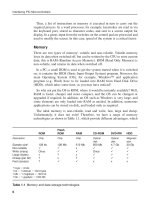
The ideal memory is non-volatile, read and write, fast, large and cheap.
Unfortunately, it does not exist! Therefore, we have a range of memory
technologies as shown in Table 1.1, which provide different advantages, which
ROM
Flash
ROM
RAM
CD-ROM
DVD-RW
HDD
Description
Chip
Chip
Chip
Optical
disk
Optical
disk
Magnetic
disk
Sample size*
Non-volatile
Write (many)
Large (bytes)
Cheap (per bit)
Fast (access)
128 kb
128 Mb
512 Mb
x
650 Mb
4.7 Gb
30 Gb
Once
x
?
?
?
x
x
?
x
x
Once
*1 byte ϭ 8 bits
1 kb ϭ 1 kilobyte ϭ 1024 bytes
1 Mb ϭ 1 megabyte ϭ 1024 kb
1 Gb ϭ 1 gigabyte ϭ 1024 Mb
Table 1.1 Memory and data storage technologies
6
x
Else_IPM-BATES_ch001.qxd
6/27/2006
10:04 PM
Page 7
PIC Hardware
may all be used with a standard PC. The main trade-off is cost, size and speed
of access. Flash ROM, as used in memory sticks and MP3 players, is closest
to the ideal, having the advantages of being non-volatile and rewritable. This
is why it is used as program memory in microcontrollers which need to be
reprogrammed, such as the PIC 16F877.
Input and Output
Without some means of getting information and signals in and out, a data
processing or digital control system would not be very useful. Ports are based
on a data register, and set of control registers, which pass the data in and out
in a controlled manner, often according to a standard protocol (method of
communication).
There are two main types of port: parallel and serial. In a parallel port, the
data is usually transferred in and out 8 bits at a time, while in the serial port
it is transmitted 1 bit at a time on a single line. Potentially, the parallel port
is faster, but needs more pins; on the other hand, the port hardware
and driver software are simpler, because the serial port must organise the
data in groups of bits, usually 1 byte at a time, or in packets, as in a network
(Figure 1.3).
Taking printers as an example, the old standard is a parallel port
(Centronics), which provides data to the printer 1 byte (8 bits) at a time via a
multipin connector. The new standard, USB (Universal Serial Bus) is a serial
data system, sending only 1 bit at a time. Potentially, the parallel connection is
8 times faster, but USB operates at up to 480 megabits (Mb) per second, and
the printer is slow anyway, so there is no problem. One advantage of using
(a)
Read/Write
Control
(b)
Internal
Data Bus
Read/Write
Control
Internal
Data Bus
External
data line
Parallel Port Register
Serial Port Register
External data lines
Figure 1.3 Parallel and serial data ports: (a) parallel; (b) serial
7
Else_IPM-BATES_ch001.qxd
6/27/2006
10:04 PM
Page 8
Interfacing PIC Microcontrollers
USB is that it provides a simple, robust connector and this outweighs the fact
that the interface protocol (driver software) is relatively complex, because this
is hidden from the user. USB also provides power to the peripheral, if required,
and the printer can be daisy-chained with other devices. USB also automatically configures itself for different peripherals, such as scanners and cameras.
In the parallel port operating in output mode, the data byte is loaded from the
internal data bus under the control of a read/write signal from the CPU. The
data can then be seen on the output pins by the peripheral; for testing, a logic
probe, logic analyser or just a simple LED indicator can be used. In input
mode, data presented at the input pins from a set of switches or other data
source are latched into the register when the port is read, and is then available
on the data bus for collection by the CPU. One of the functions of the port is
to separate the internal data bus from the external hardware, and the other is to
temporarily store the data. The data can then be transferred to memory, or
otherwise processed, as determined by the CPU program.
The serial port register also loads data from the internal bus in parallel, but
then sends it out 1 bit at a time, operating as a shift register. If an asynchronous
serial format is used, such as RS232 (COM ports on old PCs), start and stop
bits are added so that bytes can be separated at the receiving end. An error
check bit is also available, to allow the receiver to detect corrupt data. In
receive mode, the register waits for a start bit, and then shifts in the data at the
same speed as it is sent. This means the clock rate for the send and receive port
must be the same. The USART (Universal Synchronous/Asynchronous
Receive/Transmit) protocol will be described in more detail later.
A USB or network port is more sophisticated, and arranges the data bytes in
packets of, say, 1k bytes, which are sent in a form which is self-clocking; that
is, there is a transition within each bit (1 or 0), so each can be picked up individually. An error-correction code follows the data, which allows mistakes to be
corrected, rather than just be detected. This reduces the need for retransmission
of incorrectly received data, as required by simple error detection. Addressing
information preceding the data allows multiple receivers to be used.
The PIC 16F877, in common with most current MCUs, does not have USB
or network interfaces built in, so we can avoid detailed consideration of these
complex protocols. It does, nevertheless, have a good selection of other interfaces, which will be discussed in detail and sample programs provided.
PIC 16F877 Architecture
Microcontrollers contain all the components required for a processor system in
one chip: a CPU, memory and I/O. A complete system can therefore be built
8
Else_IPM-BATES_ch001.qxd
6/27/2006
10:04 PM
Page 9
PIC Hardware
using one MCU chip and a few I/O devices such as a keypad, display and other
interfacing circuits. We will now see how this is done in practice in our typical
microcontroller.
PIC 16F877 Pin Out
Let us first consider the pins that are seen on the IC package, and we can then
discover how they relate the internal architecture. The chip can be obtained in
different packages, such as conventional 40-pin DIP (Dual In-Line Package),
square surface mount or socket format. The DIP version is recommended for
prototyping, and is shown in Figure 1.4.
Most of the pins are for input and output, and arranged as 5 ports: A(5), B(8),
C(8), D(8) and E(3), giving a total of 32 I/O pins. These can all operate as
simple digital I/O pins, but most have more than one function, and the mode of
operation of each is selected by initialising various control registers within the
chip. Note, in particular, that Ports A and E become ANALOGUE INPUTS by
default (on power up or reset), so they have to set up for digital I/O if required.
Port B is used for downloading the program to the chip flash ROM (RB6 and
RB7), and RB0 and RB4–RB7 can generate an interrupt. Port C gives access
to timers and serial ports, while Port D can be used as a slave port, with Port
E providing the control pins for this function. All these options will be
explained in detail later.
Reset = 0, Run = 1
Port A, Bit 0 (Analogue AN0)
Port A, Bit 1 (Analogue AN1)
Port A, Bit 2 (Analogue AN2)
Port A, Bit 3 (Analogue AN3)
Port A, Bit 4 (Timer 0)
Port A, Bit 5 (Analogue AN4)
Port E, Bit 0 (AN5, Slave control)
Port E, Bit 1 (AN6, Slave control)
Port E, Bit 2 (AN7, Slave control)
+5V Power Supply
0V Power Supply
(CR clock) XTAL circuit
XTAL circuit
Port C, Bit 0 (Timer 1)
Port C, Bit 1 (Timer 1)
Port C, Bit 2 (Timer 1)
Port C, Bit 3 (Serial Clocks)
Port D, Bit 0 (Slave Port)
Port D, Bit 1 (Slave Port)
MCLR
RA0
RA1
RA2
RA3
RA4
RA5
RE0
RE1
RE2
VDD
Vss
CLKIN
CLKOUT
RC0
RC1
RC2
RC3
RD0
RD1
1
2
3
4
5
6
7
8
9
10
11
12
13
14
15
16
17
18
19
20
40
39
38
37
36
35
34
33
32
31
30
29
28
27
26
25
24
23
22
21
RB7
RB6
RB5
RB4
RB3
RB2
RB1
RB0
VDD
Vss
RD7
RD6
RD5
RD4
RC7
RC6
RC5
RC4
RD3
RD2
Port B, Bit 7 (Prog. Data, Interrupt)
Port B, Bit 6 (Prog. Clock, Interrupt))
Port B, Bit 5 (Interrupt)
Port B, Bit 4 (Interrupt)
Port B, Bit 3 (LV Program)
Port B, Bit 2
Port B, Bit 1
Port B, Bit 0 (Interrupt)
+5V Power Supply
0V Power Supply
Port D, Bit 7 (Slave Port)
Port D, Bit 6 (Slave Port)
Port D, Bit 5 (Slave Port)
Port D, Bit 4 (Slave Port)
Port C, Bit 7 (Serial Ports)
Port C, Bit 6 (Serial Ports)
Port C, Bit 5 (Serial Ports)
Port C, Bit 4 (Serial Ports)
Port D, Bit 3 (Slave Port)
Port D, Bit 2 (Slave Port)
Figure 1.4 PIC 16F877 pin out
9
Else_IPM-BATES_ch001.qxd
6/27/2006
10:04 PM
Page 10
Interfacing PIC Microcontrollers
The chip has two pairs of power pins (VDD ϭ ϩ5 V nominal and Vss ϭ 0 V),
and either pair can be used. The chip can actually work down to about 2 V supply, for battery and power-saving operation. A low-frequency clock circuit
using only a capacitor and resistor to set the frequency can be connected to
CLKIN, or a crystal oscillator circuit can be connected across CLKIN and
CLKOUT. MCLR is the reset input; when cleared to 0, the MCU stops, and
restarts when MCLR ϭ 1. This input must be tied high allowing the chip to run
if an external reset circuit is not connected, but it is usually a good idea to
incorporate a manual reset button in all but the most trivial applications.
PIC 16F877 Block Diagram
A block diagram of the 16F877 architecture is given in the data sheet, Figure 1-2
(downloadable from www.microchip.com). A somewhat simplified version is
given in Figure 1.5, which emphasises the program execution mechanism.
The main program memory is flash ROM, which stores a list of 14-bits
instructions. These are fed to the execution unit, and used to modify the RAM
file registers. These include special control registers, the port registers and a set
of general purpose registers which can be used to store data temporarily. A separate working register (W) is used with the ALU (Arithmetic Logic Unit) to
process data. Various special peripheral modules provide a range of I/O options.
There are 512 RAM File Register addresses (0–1FFh), which are organised
in 4 banks (0–3), each bank containing 128 addresses. The default (selected
on power up) Bank 0 is numbered from 0 to 7Fh, Bank 1 from 80h to FFh and
so on. These contain both Special Function Registers (SFRs), which have a
dedicated purpose, and the General Purpose Registers (GPRs). The file registers are mapped in Figure 2-3 of the data sheet. The SFRs may be shown in
the block diagram as separate from the GPRs, but they are in fact in the same
logical block, and addressed in the same way. Deducting the SFRs from the
total number of RAM locations, and allowing for some registers which are repeated in more than one bank, leaves 368 bytes of GPR (data) registers.
Test Hardware
We need to define the hardware in which we will demonstrate PIC program
operation. Initially, a block diagram is used to outline the hardware design
(Figure 1.6). The schematic symbol for the MCU is also shown indicating the pins
to be used. For this test program, we simply need inputs which switch between 0
V and ϩ5 V, and a logic indication at the outputs. For simulation purposes, we will
see that the clock circuit does not have to be included in the schematic; instead, the
clock frequency must be input to the MCU properties dialogue. The power supply
pins are implicit – the simulated MCU operates at ϩ5 V by default. Unused pins
can be left open circuit, as long as they are programmed as inputs.
10