Handbook of heterogeneous catalysis vol 3 incomplete knozinger
Bạn đang xem bản rút gọn của tài liệu. Xem và tải ngay bản đầy đủ của tài liệu tại đây (15.76 MB, 574 trang )
Handbook of
Heterogeneous Catalysis
Volume 3
Edited by
G. Ertl, H. Knozinger, J.Weitkamp
VCH
A Wiley company
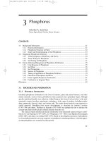
Contents
1
Introduction
1.1
1.1.1
1.1.2
1.3
1.4
.5
.6
.6.1
.6.2
.6.3
.7
.7.1
.7.2
.7.3
.7.4
.7.5
.7.6
.8
.8.1
.8.2
.8.3
Principles of Heterogeneous Catalysis 1
Introduction 1
Catalytic Cycle 1
Kinetic Steady State 2
Microscopic Reversibility 2
Principle of Sabatier 3
Active Sites and Catalyst Modifiers 5
Ideal Surfaces 5
Real Surfaces 5
Catalyst Modifiers 6
Catalyst Life Cycle 7
Preparation 7
Activation 8
Reconstruction 8
Deactivation 8
Regeneration 9
Decommission 9
Tradeoffs 9
Activity and Selectivity 10
Accessibility 10
Activity, Selectivity, Stability, and
Accessibility 11
Principles of Assisted Catalyst Design 11
Development of the Science of
Catalysis 13
Early Concepts: Berzelius, Liebig,
Faraday 13
Wilhelm Ostwald 17
The Concepts of Kinetics and Intermediate
Compounds 18
Negative Catalysis - Autocatalysis 22
Adsorption 22
Active Site - Geometric or Electronic? 24
Selected Systems 27
Ammonia Synthesis 27
Acid Catalysis 28
Zeolites 29
Ions in Catalysis 29
Hydrogenation 30
Oxidation 32
Summary 33
Development of Industrial Catalysis 35
Introduction 35
The Period from 1910 to 1938 36
The Period from 1938 to 1965 37
Catalytic Cracking 38
Catalytic Alkylation 40
Catalytic Dehydrogenation and Catalytic
Reforming 40
1.1.9
1.2
1.2.1
.2.2
.2.3
.2.4
.2.5
.2.6
.2.7
.2.7.1
.2.7.2
.2.7.3
.2.7.4
.2.7.5
.2.7.6
.2.8
.3
.3.1
.3.2
33
.3.3.1
.3.3.2
.3.3.3
1
1.3.3.4
1.3.3.5
1.3.3.6
1.3.3.7
1.3.3.8
1.3.3.9
1.3.3.10
1.3.4
1.3.4.1
1.3.4.2
1.3.4.3
Hydrogenation and Hydrodesulfurization 41
Hydrocracking 41
Dehydrogenation 41
Isomerization 42
Oxidation 42
Polymerization 43
Zeolites 43
The Period from 1965 to 1990 44
Shape Selectivity 44
Environmental Catalysis 44
Other Industrial Applications of
Catalysis 47
Preparation of Solid Catalysts
2.0
2.0. 1
2.0. 1.1
2.0. 1.2
2.0. 1.3
2.0. 1.4
2.0. 1.5
2.0 1.6
2.0 1.7
2.0 1.8
2.0.1.9
2.0 1.10
2.0 2
2.0 3
2.0 3.1
2.0.3.2
2.1
2.1
2.1 1.1
2.1 1.2
2.1 1.3
2.1 1.4
2.1 1.5
2.1 .1.6
2.1 2
2.1 .2.1
2.1 .2.2
2.1 .2.3
2.1 .2.4
49
Developing Industrial Catalysts 49
Properties and Characteristics of Industrial
Catalysts 49
Activity 49
Selectivity 49
Stability 49
Morphology 50
Mechanical Strength 50
Thermal Characteristics 50
Regenerability 50
Reproducibility 50
Originality 51
Cost 51
The Ideal Catalyst and the Optimum
Catalyst 51
Catalyst Development 51
Devising the First Catalytic Formulas 52
Optimization of a Typical Catalytic
Formula 53
Bulk Catalysts and Supports 54
Fused Catalysts 54
Introduction 54
Concept of Fused Catalysts 54
Thermodynamic and Kinetic Considerations 57
Sulfuric Acid Catalyst 59
Metallic Glasses 60
Mesostructure of Fused Catalyst
Materials 63
Skeletal Metal Catalysts 64
Introduction 64
General Aspects 64
Skeletal Nickel Catalysts 66
Promoted Skeletal Nickel Catalysts 67
Contents X X I I I
2.1.2-5
2.1.26
2.1.2-7
2.1-2-8
2.1-3
2.1-3.1
2.1.3.2
2.1-3.3
2.1-3.4
2.1-4
2.1A1
2.1.4.2
2.1-4.3
2.1A4
2.1.4.5
2.1.4.6
2.1.5
2.1.5.1
2.1.5.2
2.1.5.3
2.1.5.4
2.1.6
2.1.6.1
2.1.6.2
2.1.6.3
2.1.7
2.1.7.1
2.1.7.2
2.1.7.3
2.1.7A
2.1.7.5
2.1.7.6
2.1.7.7
2.1.8
2.1.8.1
2.1.8.2
2.1.8.3
2.1.9
2.1.9.1
2.1.9.2
2.1.9.3
2.1.9.4
2.1.9.5
2.1.9.6
2.1.9.7
2.1.9.8
Skeletal Cobalt Catalysts 67
Skeletal Copper Catalysts 67
Promoted Skeletal Copper Catalysts 69
Skeletal Copper-Zinc Catalysts 69
Precipitation and Coprecipitation 72
Introduction 72
General Principles Governing Precipitation
from Solutions 73
Influencing the Properties of the Final
Product 77
Prototypical Examples of Precipitated
Catalysts and Supports 80
Sol-Gel Process 86
Introduction 86
Important Parameters in Sol-Gel
Preparation 86
Advantages of Sol-Gel Preparation 89
Catalytic Membranes 93
Other Sol-Gel Materials 93
Summary 93
Flame Hydrolysis 94
Manufacture 94
Physicochemical Properties of Fumed
Oxides 95
Preparation of Formed Supports 98
Applications 99
Solid-State Reactions 100
Why Solid-State Reactions? 100
Description of Preparative Methods 105
Conclusions and Prospects 117
Heteropoly Compounds 118
Structure and Catalytic Properties 118
Heteropolyacids - Acid Forms in Solid State
and in Solution 119
Salts of Heteropolyacids - Cation-Exchanged
Forms 123
Mixed-Coordinated Heteropoly Compounds 125
Metal-Coordinated Heteropolyanions 126
Heteropolyanions Intercalated in Layered
Double Hydroxides 128
Supported Heteropoly Compounds 128
High-Surface Transition Metal Carbides and
Nitrides 132
General Properties of Transition Metal
Carbides and Nitrides 132
Thermodynamic Considerations in the
Preparation of Carbides and Nitrides 132
Survey of Preparative Methods 134
Carbons 138
Introduction 138
Structural Chemistry of Carbon 138
Overview 139
Basic Structures 140
Loosely Defined Structures 142
Formation of Carbon Materials, General
Pathways 148
Formation of Carbon Materials, Mechanistic
Aspects 149
Catalytic Formation of Carbon from
Molecules 151
2. .9.9
2. .9.10
2. .9.11
2. .9.12
2. 1.9.13
2. 1.9.14
2. 1.9.15
2. 1.9.16
2. 1.9.17
2. 1.9.18
2. 1.9.19
2. 1.9.20
2.1.9.21
2.1.9.22
2.2
2.2.1
2.2.1.1
2.2.1.2
2.2.1.3
2. 2.1.4
2.2.1.5
2.2.1.6
2.2.2
2.2.2.0
2.2.2.1
2.2.2.2
2.2.2.3
2.2.2.4
2.2.2.5
2.3
2.3.1
2.3.
2.3.
2.3.
2.3.
2.3.
2.3.2
2.3.2.1
2.3.2.2
2.3.2.3
2.3.3
2.3.3.1
2.3.3.2
2.3.3.3
2.3.3.4
2.3.3.5
Carbon on Noble-Metal Catalysts 152
Carbon Formation in Zeolites 153
Graphitization of Carbons 155
Reaction of Oxygen with Carbon 156
Surface Chemistry of Carbon 161
Non-Oxygen Heteroelements on Carbon
Surfaces 163
Surface Oxygen Groups 165
Carbon as Catalyst Support 177
Carbon as Catalyst 181
Case Studies of Catalytic Applications 182
Catalytic Removal of NO by Carbon 183
Removal of Carbon Deposits From Catalyst
Materials 184
Activation of Oxygen on Carbon
Surfaces 185
Conclusions 188
Supported Catalysts 191
Deposition of Active Component 191
Impregnation and Ion Exchange 191
Anchoring and Grafting of Coordination
Metal Complexes onto Oxide Surfaces 207
Spreading and Wetting 216
Heterogenization of Complexes and
Enzymes 231
Preparation of Supported Catalysts by
Deposition-Precipitation 240
Redox Methods for Preparation of Bimetallic
Catalysts 257
Formation of Final Catalysts 264
Introduction and Background 264
Activation of Supported Catalysts by
Calcination 271
Activation of Supported Catalysts by
Reduction 273
Reduction-Sulfidation 278
Other Methods of Activation 282
Conclusions 283
Zeolites and Related Molecular Sieves 286
A Synoptic Guide to the Structures of Zeolitic
and Related Solid Catalysts 286
Introduction 286
Framework Density, Nomenclature and
Secondary Building Units 287
Microporous Solids as Catalysts 290
Survey of Zeolitic and Related Catalysts 290
Mesoporous Solids as Catalysts 308
Hydrothermal Zeolite Synthesis 311
Introduction 311
Zeolitization in General 311
Synthesis of Industrial Zeolites 321
Acidity and Basicity in Zeolites 324
Introduction 324
Experimental Methods for Identification and
Quantification of Acid and Base Sites in
Zeolites 324
Acid Properties of Aluminosilicatc-Typc
Zeolites 329
Acid Properties of Mctallosilicates 340
Acid Properties of Phosphate-Based
Zeolites 343
XXIV Contents
2.3.3.6
2.3.4
2.3.4.1
2.3.4.2
2.3.4.3
2.3.4.4
2.3.4.5
2.3.5
2.3.5.1
2.3.5.2
2.3.5.3
2.3.6
2.3.6.1
2.3.6.2
2.3.6.3
2.3.6.4
2.3.6.5
2.4
2.4.1
Basicity of Zeolites 354
Metal Clusters in Zeolites 365
Introduction 365
Metal Clusters Versus Macroscopic
Metals 365
Preparation of Mono- or Bimetallic Clusters in
Zeolites 366
Interaction of Metal Clusters and Zeolite
Protons 367
Effects of Zeolite Geometry on Catalysis 371
Zeolite-Entrapped Metal Complexes 374
Synthesis of Zeolite-Entrapped Metal
Complexes 374
Characterization 378
Catalysis by Zeolite-Entrapped Transition
Metal Complexes 382
Pillared Clays 387
Introduction 387
Pillars 390
Pillared Clays 393
Catalytic Properties 400
Conclusions 402
Solid Superacids 404
Sulfate-Treated Metal Oxides, Mixed Oxides,
and Those Modified with Platinum 404
2.4.1.1
2.4.1.2
2.4.1.3
2.4.1.4
2.4.2
2.5
2.5.1
2.5.2
2.5.2.1
2.5.2.2
2.5.2.3
2.5.2.4
2.5.3
2.6
2.6.1
2.6.2
2.6.2.1
2.6.2.2
2.6.3
2.6.4
2.6.5
Preparative Methods 404
Morphology and Surface Properties 405
Structure of Superacid Sites 407
Catalytic Properties 408
Other Solid Superacids 410
Catalyst Forming 412
Forming Microgranules 412
Forming Granules 414
Pelletizing 414
Extrusion 416
Pan Granulation 416
Miscellaneous Forming Operations 417
Organizing a Catalyst-Manufacturing
Process 417
Computer-Aided Catalyst Design 419
Introduction 419
Heuristics in Catalyst Design 420
Knowledge-Based Systems 421
Neural Networks 423
Deterministic Methods in Catalyst
Design 424
Chemical Reaction Engineering Aspects
Conclusions 425
Contents
Elementary Steps and Mechanisms
5.
5.1.1
5. .1.1
5. .1.2
5. 1.1.3
5. .1.4
5. .1.5
5. 1.2
5. 1.2.1
5. 1.2.2
5.1.2.3
5.1.2.4
5.2
5.2.1
5.2.1.1
5.2.1.2
5.2.1.3
5.2.1.4
5.2.1.5
5.2.1.6
5.2.1.7
5.2.1.8
5.2.1.9
5.2.2
5.2.2.1
5.2.2.2
5.2.2.3
5.2.2.4
5.2.2.5
5.2.3
5.2.3.1
5.2.3.2
5.2.3.3
5.2.3.4
5.2.4
5.2.4.1
5.2.4.2
911
Chemisorption 911
Principles of Chemisorption 911
Introduction 911
Thermodynamics and Energetics 912
Sticking 921
Surface Diffusion
926
Structure Sensitivity 927
Chemisorption Theory 942
Introduction 942
Formal Chemisorption Theory 943
Concepts in Chemisorption 952
The Surface Chemical Bond: A
Summary 956
Microkinetics 958
Rates of Catalytic Reactions 958
Introduction 958
Turnover Rate or Turnover Frequency:
Generalities 959
Examples of Turnover Rate
Measurements 960
Comparison of Rate Data 961
Relationships between Thermodynamics and
Kinetics 963
Most Abundant Reactive Intermediates and
Kinetically Significant Steps 964
Kinetic Coupling in Catalytic Cycles: Effect on
Rate 966
Kinetic Coupling between Catalytic Cycles:
Effect on Selectivity 969
Conclusions 970
Dynamics of Surface Reactions 972
Introduction 972
Direct Versus Trapping-Mediated Surface
Reactions 972
Transition State Theory of Surface Reaction
Rates 974
Trapping-Mediated Surface Reactions 979
Synopsis 983
Theoretical Modeling of Catalytic
Reactions 984
Introduction 984
Different Approaches to Simulations of
Surface Reaction Kinetics 985
Simplest Mean-Field Approach 987
Selected Examples 990
Theory of Surface-Chemical Reactivity 991
Introduction 991
Outline 993
5.2.4.3
5.2.4.4
5.2.4.5
5.2.4.6
5.2.5
5.2.5.1
5.2.5.2
5.2.5.3
5.2.6
5.2.6.1
5.2.6.2
5.2.6.3
5.2.6.4
5.2.6.5
5.2.7
5.2.7.1
5.2.7.2
5.2.7.3
5.2.7.4
5.2.7.5
5.2.7.6
5.2.8
5.2.8.1
5.2.8.2
5.2.8.3
5.2.8.4
5.2.8.5
5.2.8.6
5.2.8.7
5.3
5.3.1
5.3.1.1
5.3.1.2
5.3.1.3
Transition Metal Surface Chemistry 994
Transition Metal Sulfide Catalyzed
Desulfurization
1000
Reactivity of Oxidic Surfaces 1001
Conclusions 1004
Isotopic Labeling and Kinetic Isotope
Effects
1005
Introduction
1005
Isotope Labeling in Heterogeneous Catalytic
Reactions 1006
Kinetic Isotope Effect
1010
Transient Catalytic Studies 1012
Importance of In Situ Transient
Studies 1012
Experimental Method
1014
Kinetics of Adsorption and Desorption
1015
Catalysis 1017
Summary 1022
Positron Emitters in Catalysis
Research 1023
Introduction
1023
Characteristics of /?-Emitters 1024
Production of Labeled Compounds 1025
Detection of /T and Annihilation
Radiation
1026
Application to Heterogeneous
Catalysis 1027
Conclusions 1031
Nonlinear Dynamics: Oscillatory Kinetics and
Spatio-Temporal Pattern Formation
1032
Introduction
1032
Overview of the Theoretical
Background
1034
CO Oxidation on Pt(110): A Case Study of a
Uniform Isothermal System 1035
Oxidation of Carbon Monoxide on Other
Surfaces 1040
Other Isothermal Systems with Oscillatory
Kinetics 1042
Thermokinetic Phenomena 1044
Some Consequences and Future
Prospects 1045
Factors Influencing Catalytic Action 1051
Substitucnt Effects
1051
Substituent, Reaction Center, and Surface
Reaction Complex 1051
Mass and Specific Effects of
Substituents 1052
Quantitative Treatment of Substituent
Effects
1054
Contents
5.3.1.4
5.3.1.5
5.3.1.6
5.3.2
5.3.2.1
5.3.2.2
5.3.2.3
5.3.2.4
5.3.2.5
5.3.2.6
5.3.3
5.3.3.1
5.3.3.2
5.3.3.3
5.3.3.4
5.3.4
5.3.4.1
5.4.3.2
5.4.3.3
5.4.3.4
5.3.5
5.3.5.1
5.3.5.2
5.3.5.3
5.3.5.4
5.3.5.5
5.3.5.6
5.4
5.4.1
5.4. 1.1
5.4. 1.2
5.4. 1.3
5.4.1 .4
5.4.1.5
5.4.2
5.4.2.1
5.4.2.2
5.4.2.3
5.4.2.4
5.4.2.5
Catalyst Characterization by the Slopes of
LFER
1057
Substituent Effects as a Tool for Elucidation of
Mechanisms 1059
Prospects
1062
Spillover Effects
1064
Definitions
1064
Direct Experimental Observations of
Spillover
1064
Interpretation of Spillover and Factors
Affecting Spillover
1068
Chemical Nature of Spillover
Species 1071
Applications of Spillover in Heterogeneous
Catalysis 1072
Conclusions 1076
Ensemble and Ligand Effects in Metal
Catalysis 1077
Introduction: Adsorption Sites on Metal
Surfaces
1077
Dissociative Chemisorption, Ensemble
Requirements 1078
"Electronic" Ligand Effect
1081
Pure and "Mixed" Ensembles on Binary
Alloys 1081
Promoters and Poisons 1084
Introduction
1084
Brief History and Present Directions of
Research
1085
Case Studies of Modifiers in Selected
Reactions Studied by a Combination of
Techniques 1087
Modifiers for Important Reactions that
Require More Detailed Studies 1098
Heterogeneous Catalysis and High Electric
Fields 1104
Introduction
1104
Electric Fields 1104
Applications of Electric Fields 1107
Field-Induced Surface Phenomena
1118
Field-Induced Phenomena on Extended
Surface Planes 1120
Summary
1120
Organic Reaction Mechanisms 1123
Hydrocarbon Reaction Mechanisms 1123
Introduction
1123
Acid-Base Catalysis 1123
Carbocations and Their Reactions 1124
Catalytic Reactions Involving Carbocation
Intermediates
1129
Metal Surface Catalysis 1134
Reaction Mechanisms of Acid-Catalyzed
Hydrocarbon Conversions in Zeolites 1137
Introduction
1137
Alkylcarbenium and Alkylcarbonium
Ions 1138
Reactions of Aliphatic Alkylcarbenium Ions in
Liquid Superacids 1139
Carbocations in Acid Zeolites 1141
Carbocations and Conversions of Short
Alkanes on Bifunctional Zeolites 1142
5.4.2.6
5.4.2.7
5.4.2.8
5.4.2.9
5.4.2.10
5.5
5.5.1
5.5.1.1
5.5.1.2
5.5.1.3
5.5.1.4
5.5.2
5.5.2.1
5.5.2.2
5.5.2.3
5.5.2.4
5.5.2.5
,
Carbocations and Conversions of Long
Alkanes on Bifunctional Zeolites 1143
Mechanistic Concepts on Protonation of
Hydrocarbons in Acid Zeolites 1144
Transition States of Acid-Catalyzed Alkane
Transformations on Zeolites 1145
Transition States of Acid-Catalyzed Transformations of Alkenes on Zeolites 1146
Conclusions 1148
Computer Simulations 1149
Computer Simulation of Structures 1149
Introduction
1149
Methods 1149
Applications 1153
Summary and Conclusion
1164
Molecular Simulation of Adsorption and
Diffusion in Zeolites 1165
Introduction
1165
Constructing a Molecular Model 1169
Molecular Simulation Techniques 1171
Example Calculations and Comparison with
Experiment
1174
Conclusions 1185
6
Kinetics and Transport Processes
6.1
Rate Procurement and Kinetic
Modeling 1189
Introduction
1189
Rate Procurement - Laboratory
Reactors 1189
Laboratory Reactors 1190
Kinetic Modeling 1195
Rate Expression
1195
Deactivation Kinetics 1197
Parameter Estimation - Model Discrimination 1198
Data Regression 1198
Kinetic Data Handling 1201
Model Testing 1201
Discrimination Between Rival Models 1203
Sequential Experimental Design 1204
Multiresponse Models 1206
Concluding Remarks 1207
Symbols 1207
Simultaneous Heat and Mass Transfer and
Chemical Reaction
1209
Introduction
1209
Mathematical Description
1212
Single Reactions (Conversion Problem) 1214
Pore Diffusion in an Isothermal Pellet 1216
Film and Pore Diffusion in an Isothermal
Pellet 1219
Film and Pore Diffusion Together with
lnterphase Heat Transfer
1219
Film and Pore Diffusion Together with
lnterphasc and Intraparticle Heat
Transfer
1222
External Heat and Mass Transfer
1225
Use of Complex Rate Expressions 1226
6.1.1
6.1.2
6.1.2.1
6.1.3
6.1.3.1
6.1.3.2
6.1.4
6.1.4.1
6.1.4.2
6.1.4.3
6.1.4.4
6.1.4.5
6.1.4.6
6.1.5
6.1.6
6.2
6.2.1
6.2.2
6.2.3
6.2.3.1
6.2.3.2
6.2.3.3
6.2.3.4
6.2.3.5
6.2.3.6
1189
Contents
6 2.4
6 2.41
6.2.4.2
6.2.5
6.2.5.1
6.2.5.2
6.2.5.3
6 2.6
6.2.6.1
6.2.6.2
6.2.6.3
6.2.7
6.2.7.1
6.2.7.2
6.2.7.3
6.3
6.3.1
6.3.2
6.3.2.1
6.3.2.2
6.3.2.3
6.3.2.4
6.3.2.5
6.3.3
6.3.3.1
6.3.3.2
6.3.3.3
6.3.3.4
6.3.4
6.3.5
Temperature Dependence and Reaction Order
of Transport-Limited Reactions 1229
Intraparticle Diffusion
1230
Interphase Mass Transfer
1231
Diagnostic Criteria and Experimental
Methods for Estimating the Influence of Heat
and Mass Transfer on the Effective Reaction
Rate 1231
Experimental Criteria
1232
Theoretical Criteria
1233
Experimental Methods for Estimating the
Influence of Heat and Mass Transfer
Effects
1233
Multiple Reactions (Selectivity Problem)
1235
Type I Selectivity 1236
Type II Selectivity 1237
Type III Selectivity
1240
Control of Selectivity in Zeolite Catalyzed
Reactions by Utilizing Diffusion
Effects
1242
Shape-Selective Catalysis 1242
Modeling of Shape-Selectivity Effects
1244
Controlled Modification of the Pore
Structure 1250
Determination of Diffusion Coefficients in
Porous Media 1252
Definitions
1252
Measurement of Transport Diffusion
1254
Steady State Measurements 1254
Time Lag Measurements 1254
Sorption Rate Measurements 1254
Frequency Response Measurements 1255
Chromatographic and Flow Methods 1256
Measurement of Self-Diffusion
1257
Elementary Steps of Diffusion
1257
Quasielastic Neutron Scattering 1257
Pulsed Field Gradient NMR
1258
Tracer Techniques 1258
Diffusion in Multicomponent Systems 1259
Correlation Between the Different
Diffusivities
1259
7.8.2
7.8.3
Metal Recovery 1279
Encapsulation/Stabilization
1280
8
Special Catalytic Systems
1283
8.1
Chemical Sensors Based on Catalytic
Reactions 1283
Introduction
1283
Definitions and Classifications 1283
Typical Examples 1283
Chemical Sensors and Heterogeneous
Catalysts: Similarities and
Differences
1289
Electronic Conductance Sensors 1290
Basic Concepts 1291
Electronic Conductance Sensors Based on
SnO2 1295
Schottky-Diode-Type Conductance Sensors
Based on TiO 2 1303
Bulk Defect Sensors Based on BaTiO3 and
Related Oxides 1304
Calorimetric Sensors 1305
Solid Electrolyte Sensors 1306
Conclusions 1308
Electrochemical Modification of Catalytic
Activity 1310
Introduction
1310
Solid Electrolyte Cells and their Relevance to
Catalysis 1310
Solid Electrolytes 1310
Solid Electrolyte Potentiometry (SEP) 1311
Potential-Programmed Reduction 1312
Electrocatalytic Operation of Solid Electrolyte
Cells 1313
The Active Use of Solid Electrolytes in
Catalysis 1314
Electrochemical Promotion or In Situ
Controlled Promotion: The NEMCA
Effect
1314
Transient and Steady-State Electrochemical
Promotion Experiments 1315
Definitions and Some Key Aspects of Electrochemical Promotion
1316
Spcctroscopic Studies 1317
Purely Catalytic Aspects of In Situ Controlled
Promotion 1319
Rate Enhancement Ratio p 1319
Promotion Index Pj 1319
Electrophobic and Electrophilic
Reactions 1320
The Work Function of Catalyst Films
Interfaced with Solid Electrolytes 1320
Dependence of Catalytic Rates and Activation
Energies on Catalyst Work Function e<t>
1321
Selectivity Modification
1322
Promotional Effects on Chcmisorption 1322
In Situ Controlled Promotion Using Aqueous
Electrolytes 1323
8.1.1
8.1.1.1
8.1.1.2
8.1.1.3
8.1.2
8.1.2.1
8.1.2.2
8.1.2.3
8.1.2.4
8.1.3
8.1.4
8.1.5
8.2
8.2.1
8.2.2
8.2.2.1
8.2.2.2
8.2.2.3
8.2.2.4
8.2.3
8.2.3.1
8.2.3.2
8.2.3.3
7
Deactivation and Regeneration
7.1
7.2.1
7.2.2
7.2.3
7.3
7.4
7.4.1
7.4.1.1
7.4.1.2
Introduction
1263
Catalyst Poisoning 1264
Catalyst Fouling 1265
Thermal Degradation
1266
Catalyst Deactivation by Poisoning 1266
Fouling 1267
Coke formed in Gas Phase Processes 1267
Non-catalytic Gas-Phase Coke 1268
Coking in Gas-Solid Catalytic
Reactions 1269
Coke Formed in Liquid-Phase Catalytic
Processes 1273
Catalyst Regeneration: Coking 1275
Thermal Deactivation
1276
Treatment of Spent Catalyst
1278
Catalyst Rejuvenation
1279
7.5
7.6
7.7
7.8
7.8.1
1263
XI
8.2.3.4
8.2.4
8.2.4.1
8.2.4.2
8.2.4.3
8.2.4.4
8.2.4.5
8.2.4.6
8.2.4.7
8.2.4.8
XII
Contents
8.2.5
8.2.6
8.3
8.3.1
8.3.2
8.3.2.1
8.3.2.2
8.3.2.3
8.3.3
8.3.4
8.3.5
8.3.5.1
8.3.5.2
8.3.5.3
8.3.6
8.3.6.1
8.3.6.2
8.3.6.3
8.3. 6.4
8.4
8.4. 1
8.4. 2
8.4.2.1
8.4. 2.2
8.4. 2.3
8.4. 3
8.4. 4
8.4.5
8.4..6
8.5
8.5 .1
8.5 .2
8.5 .3
8.5 .4
8.5 .5
8.5 .6
8.6
8.6.1
8.6 2
8.6 .2.1
8.6.2.2
8.6 .2.3
8.6 .2.4
Potential Applications 1324
Conclusions 1324
Electrocatalysis 1325
Definition and Relationship to Heterogeneous
Catalysis 1325
Some Fundamentals of Redox Reactions at
Electrodes 1326
Galvani Potential, Overvoltage and Current/
Voltage Curves 1326
Theoretical Model on the Basis of the FranckCondon Principle 1326
Redox Reactions Occurring in Several
Steps 1327
Catalysis of One-Electron Transfer
Reactions 1328
Hydrogen Electrode Reaction 1328
Oxygen Electrode Reaction 1331
Energetics 1332
Bridge Bonding of Oxygen Molecules and
Reduction Pathway 1333
Comments on Catalysis of the Oxygen
Electrode 1333
Trends in the Application of Electrocatalysis 1333
Fuel Cells 1333
Production of Chemicals 1334
Electrochemical Sensors 1335
Non-Faradaic Electrochemical Modification
of Catalytic Activity: NEMCA
1337
Catalysis in Supercritical Media 1339
Properties of Supercritical Fluids 1339
Thermodynamics and Kinetics of Reactions in
Supercritical Fluids 1340
Clustering 1340
Pressure Effects
1341
Phase Behavior 1342
Motivation for Catalysis in Supercritical
Media 1342
Case Studies of Heterogeneous Catalysis in
SCFs 1344
Other Applications of SCFs and
Catalysis 1346
Concluding Remarks 1346
Microwave Heating in Catalysis 1347
Microwave Energy and Microwave
Heating 1347
Dielectric Polarization
1348
Interfacial Polarization
1348
Ionic Conduction
1348
Microwave Heating 1348
Current Research
1349
Sonocatalysis 1350
Introduction and the Origins of Sonochemistry
1350
Effects of Ultrasound on Heterogeneous
Catalysts 1352
Metal Powders 1352
Metal Oxides as Oxidation Catalysts 1354
Silica, Alumina, and Zeolites 1354
Supported Metal Catalysts 1355
8.6.2.5
8.6.3
Polymerization Catalysts 1356
Concluding Remarks 1356
9
Laboratory Reactors
9.1
Laboratory Catalytic Reactors: Aspects of
Catalyst Testing 1359
Introduction
1359
Reactor Systems 1361
Classification
1361
Balance Equations 1362
Continuous-Flow Stirred-Tank Reactor
(CSTR) 1362
Plug-Flow Reactor (PFR) 1363
Laboratory Systems 1365
Mass and Heat Transfer
1365
Extraparticle Gradients 1365
Intraparticle Gradients 1366
Catalyst Bed Gradients 1369
Comparison Criteria 1370
Mass Transport 1371
Heat Transport 1371
Effect of Particle Transport Limitations on the
Observed Behavior 1371
Diagnostic Experimental Tests 1372
Extraparticle Concentration Gradients 1372
Intraparticle Concentration Gradients 1372
Temperature Gradients 1373
Proper Catalyst Testing and Kinetic
Studies 1373
Notation
1374
Ancillary Techniques in Laboratory Units for
Catalyst Testing 1376
Introduction
1376
Overall Equipment 1377
Generation of Feed Streams 1378
Devices for Product Sampling 1380
Elemental Analysis of Carbonaceous Deposits
on Catalysts 1383
Concluding Remarks 1386
Acknowledgements 1386
Catalytic Membrane Reactors 1387
Introduction
1387
Features of Catalytic Membrane
Reactors 1387
Development of CMRs 1387
Membranes for CMR Applications 1387
Characterization of Porous
Membranes 1389
Gas Transport and Separation in Porous
Membranes 1390
Catalyst-Membrane Combinations 1391
Applications of CMRs 1392
Equilibrium-Restricted Reactions 1392
Controlled Addition of Reactants 1393
Active Contactor 1394
Conclusions 1395
Glossary
1396
9.1.1
9.1.2
9.1.2.1
9.1.2.2
9.1.2.3
9.1.2.4
9.1.2.5
9.1.3
9.1.3.1
9.1.3.2
9.1.3.3
9.1.4
9.1.4.1
9.1.4.2
9.1.5
9.1.6
9.1.6.1
9.1.6.2
9.1.6.3
9.1.7
9.1.8
9.2
9.2.1
9.2.2
9.2.3
9.2.4
9.2.5
9.2.6
9.2.7
9.3
9.3.1
9.3.2
9.3.2.1
9.3.2.2
9.3.2.3
9.3.2.4
9.3.2.5
9.3.3
9.3.3.1
9.3.3.2
9.3.3.3
9.3.4
9.3.5
1359
Contents XIII
10
Reaction Engineering
10.1
10.1.1
10.1.2
Catalytic Fixed-Bed Reactors 1399
Introduction
1399
Catalyst Shapes for Fixed-Bed
Reactors 1401
Random Packings 1401
Monoliths 1402
Gas Flow and Pressure Drop in Fixed
Beds 1404
Heat Transfer in Catalyst-Filled Tubes 1405
Comparison of Different Catalyst
Shapes 1406
Types of Fixed-Bed Reactors 1406
Adiabatic Reactors 1406
Multistage Reactors 1408
Fixed-Bed Reactors which are Cooled or
Heated Through the Wall 1410
Autothermal Reactors 1415
Multifunctional Reactors 1420
Parametric Sensitivity, Runaway and Safety of
Fixed-Bed Reactors 1422
Runaway
1422
Safety Aspects 1423
Conclusions 1423
List of Symbols 1424
References 1424
Fluidized-Bed Reactors 1426
Introduction
1426
The Fluidization Principle 1426
Forms of Fluidizcd Beds 1426
Advantages and Disadvantages of the
Fluidized-Bed Reactor 1427
Fluid-Mechanical Principles 1427
Minimum Fluidization Velocity 1427
Fluidization Properties of Typical Bed
Solids 1429
Gas Distribution
1429
Gas Jets in Fluidized Beds 1430
Bubble Development 1430
Elutriation 1431
Circulating Fluidized Beds 1432
Attrition of Solids 1433
Gas Mixing in Fluidized-Bed Reactors
1435
Gas Mixing in Bubbling Fluidized
Beds 1435
Gas Mixing in Circulating Fluidized
Beds 1435
Industrial Applications 1436
Heterogeneous Catalytic Gas-Phase
Reactions 1436
Polymerization of Alkenes 1438
Modeling of Fluidized-Bed Reactors 1438
Bubbling Fluidized-Bed Reactors 1438
Circulating Fluidized-Bed Reactors 1439
Scale-Up 1441
Slurry Reactors 1444
Introduction
1444
Properties of Slurry Reactors 1444
10.1.2.1
10 A .2.2
10 1.2.3
10.1.2.4
10.1.2.5
10.1.3
10.1.3.1
10.1.3.2
10 1.3.3
10.1.3.4
10.1.3.5
10.1.4
10.1.4.1
10.1.4.2
10.1.5
10.1.6
10.1.7
10.2
10.2.1
10.2.1.1
10.2.1.2
10.2.1.3
10.2.2
10.2.2.1
10.2.2.2
10.2.2.3
10.2.2.4
10.2.2.5
10.2.2.6
10.2.2.7
10.2.2.8
10.2.3
10.2.3.1
10.2.3.2
10.2.4
10.2.4.1
10.2.4.2
10.2.5
10.2.5.1
10.2.5.2
10.2.6
10.3
10.3.1
10.3.2
1399
10.3.3
10.3.4
10.3.4.1
10.3.4.2
10.3.4.3
10.3.5
10.3.5.1
Types of Slurry Reactors 1445
Hydrodynamics of Slurry Reactors 1446
Minimum Suspension Criteria 1446
Gas Holdup 1449
Axial Mixing in Slurry Reactors 1450
Mass Transfer with Chemical Reaction 1452
The Volumetric Liquid-Side Mass Transfer
Coefficient at the Gas-Liquid Interface
1453
10.3.5.2 The True Gas-Liquid Specific Contact Area
(a) and the Liquid-Side Mass Transfer
Coefficient (kL)
1456
10.3.5.3 The Volumetric Gas-Side Mass Transfer
Coefficient (kGa)
1456
10.3.5.4 The Mass Transfer Coefficient at the LiquidSolid Interface ks
1456
10.3.6
Enhancement of Gas-Liquid Mass
Transfer
1458
10.3.6.1
Enhancement by Physical Adsorption
1458
10.3.6.2
Particles Catalyze a Chemical Reaction
Involving the Absorbed Gas Phase
Component
1459
10.3.7
Towards High-Intensity Slurry
Reactors 1460
10.3.8
Symbols 1460
10.4
Unsteady-State Reactor Operation 1464
10.4.1
Introduction
1464
10.4.2
Dynamic Kinetic Model 1465
10.4.3
General Approaches to Reactor
Modeling 1467
10.4.4
Analysis and Optimization of Cyclic
Processes 1470
10.4.4.1
General Optimal Periodic Control
Problem
1470
10.4.5
Reaction Performance Improvement 1471
10.4.6
Dynamic Phenomena in a Fixed-Bed Reactor
1472
10.4.7
Reverse-Flow Operation in Fixed-Bed
Reactors 1474
10.4.8
Reaction-Separation Processes 1476
10.4.8.1
Continuous Countercurrent Moving-Bed
Chromatographic Reactor 1476
10.4.8.2
Reaction Pressure Swing Adsorption
1476
10.4.9
Partial Oxidation in Fluidized-Bed and Riser
Reactors 1477
10.4.9.1
Internal Circulation of a Catalyst in Fluidized
Beds 1477
10.4.10
Miscellaneous Examples 1477
10.4.10.1 Fluctuations of the Inlet Temperature in
Fixed-Bed Catalytic Reactors 1477
10.4.10.2 Stabilization of Unstable Steady State 1477
10.4.10.3 Liquid-Gas-Solid Reactor Systems 1478
10.5
Reactive Distillation 1479
10.5.1
Introduction
1479
10.5.2
Conceptual Approach to Reactive
Distillation 1480
10.5.3
Computational Procedures 1480
10.5.3.1
Problem Definition
1480
10.5.3.2
Evolution of Algorithms 1480
10.5.3.3
Relaxation Techniques 1481
XIV Contents
10.5.4.1
10.5.4.2
10.5.5
10.5.6
Tearing and Partitioning 1481
Global Approaches 1481
Practical Realization of Reactive
Distillation
1482
Packed Towers 1483
Tray Towers 1483
Selected Processes 1484
Conclusions 1485
11
Annexes
11.
11. .1
11. .2
11. .2.1
11. .2.2
1 .2.3
1 .3
.1.3.1
Standard Catalysts 1489
Introduction 1489
EUROCAT Metal Catalysts 1490
EUROPT-1
1490
EUROPT-3 and EUROPT^ 1495
EURONI-1
1496
Other EUROCAT Catalysts 1497
Vanadia-Titania EUROCAT
Oxides 1497
EUROTS-1 Zeolite 1499
EUROCOMO Catalyst 1500
Other Programmes 1500
Japanese Programme 1500
Russian Programme 1501
Northwestern University Programme 1502
American Society for Testing Materials
(ASTM) 1502
British Standards Institute (BSI) 1502
IUPAC/SCI/NPL Programme 1502
10.5.3.4
10.5.3.5
10.5.4
.1.3.2
.1.3.3
.1.4
.1.4.1
.1.4.2
.1.4.3
.1.4.4
11.1.4.5
11.1.4.6
1489
11.1.4.7
11.1.5
11.2
11.2.1
.2.1.1
.2.1.2
.2.1.3
.2.1.4
.2.1.5
.2.1.6
11.2.1.7
11.2.1.8
11.2.1.9
.2.2
.2.2.1
.2.2.2
.2.2.3
.2.2.4
.2.2.5
1.2.3
.2.3.1
.2.3.2
.2.3.3
.2.3.4
.2.3.5
Measurements of Surface Area and
Porosity 1502
Summary and Conclusions 1502
IUPAC Recommendations 1503
Reporting Physisorption Data for Gas/Solid
Systems 1503
Introduction
1503
General Definitions and Terminology
1504
Methodology
1505
Experimental Procedures 1507
Evaluation of Adsorption Data
1508
Determination of Surface Area 1510
Assessment of Mesoporosity
1512
Assessment of Microporosity
1513
General Conclusions and Recommendations 1514
Catalyst Characterization
1516
Introduction
1516
Catalyst Formulation and Methods of Its
Preparation
1516
Physical Properties 1520
Fine Structure 1522
Catalytic Properties 1524
Methods and Procedures for Catalyst
Characterization
1529
Introduction
1529
Catalyst Preparation
1529
Characterization of Surface Properties by
Adsorption Methods 1536
Fine Structure of Catalysts [20] 1540
Catalytic Properties 1546
2 Preparation of Solid Catalysts
2.0.1.1 Activity
2.0 Developing Industrial Catalysts
A high activity will be reflected either in high productivity from relatively small reactors and catalyst
volumes or in mild operating conditions, particularly
temperature, that enhance selectivity and stability if the
thermodynamics is more favorable.
2.1 Bulk Catalysts and Supports
2.2 Supported Catalysts
2.3 Zeolites and Related Molecular Sieves
2.4 Solid Superacids
2.0.1.2 Selectivity
2.5 Shaping of Catalysts and Supports
High selectivity produces high yields of a desired
product while suppressing undesirable competitive and
consecutive reactions. This means that the texture of
the catalyst (in particular pore volume and pore distribution) should be improved toward reducing limitations by internal diffusion, which in the case of consecutive reactions rapidly reduces selectivity.
2.6 Computer-aided Catalyst Design
2.0 Developing Industrial Catalysts
j
J. F. LEPAGE
Once an active species and perhaps its support have
been selected, the task is to construct from precursors
of these active species a catalytic structure whose properties and characteristics will meet the demands of an
industrial user. One must avoid creating a structure
that is only a laboratory curiosity which for technical
or economic reasons can not be manufactured on industrial scale.
2.0.1 Properties and Characteristics of
Industrial Catalysts
In addition to the fundamental properties that come
from the very definition of a catalyst, i.e., activity, selectivity, and stability, industrial applications require
that a catalyst be regenerable, reproducible, mechanically and thermally stable, original, economical, and
possess suitable morphological characteristics.
x)
Reprinted with permission from J. F. Le Page, Applied Heterogeneous Catalysis - Design, Manufacture, Use of Solid Catalysts,
Editions Technip, Paris, 1987.
2.0.1.3 Stability
A catalyst with good stability will change only very
slowly over the course of time under conditions of
use and regeneration. Indeed, it is only in theory that
a catalyst remains unaltered during reaction. Actual
practice is far from this ideal. Some of the things that
lead to a progressive loss of activity or selectivity or
mechanical strength are as follows:
(a) Coke forms on some catalysts through the intervention of parasitic reactions of hydrogenolysis,
polymerization, cyclization, and hydrogen transfer.
(b) Reactants, products or poisons may attack active
agents or the support.
(c) Volatile agents, such as chlorine, may be lost during reactions such as reforming.
(d) The crystals of a deposited metal may become
enlarged or regrouped. A change in the crystalline
structure of the support can cause a loss of mechanical strength.
(e) Progressive adsorption of trace poisons in the feed
or products may reduce activity. It has been
pointed out that industrial feedstocks are rarely
pure products, but mixtures containing portions of
impurities that must sometimes be eliminated beforehand so that the catalyst can be used.
References see page 53
50
2 Preparation of Solid Catalysts
2.0.1.4 Morphology
The external morphological characteristics of a catalyst, i.e. its form and grain size, must be suited to the
corresponding process. For moving or boiling bed reactors the spherical form is recommended for reducing
problems of attrition and abrasion. In a fluid bed, a
spherical powder is preferred for limiting attrition, and
its grains should have well determined size distributions
for obtaining good fluidization. In a fixed bed, beads,
rings, pellets, extrudates, or flakes can be used; but
their form and dimensions will have an influence on
the pressure drop through the bed. Thus for a given
equivalent diameter, catalysts can be classified according to the relative pressure drops they cause, as follows:
of the catalytic mass leads to reduced temperature gradients within the grain, as well as in the catalytic bed,
for endothermic or exothermic reactions, by improving
heat transfer. For other catalysts, the specific heat assumes more importance; a high specific heat permits a
catalytic cracking catalyst to carry a large thermal load
from the combustion of coke back to the endothermic
cracking reaction, where it is usefully consumed. Ry
contrast, catalysts in catalytic mufflers are more efficient when they are quickly carried to a high temperature by the combustion gases, and a low specific heat
can be advantageous.
2.0.1.7 Regenerability
Rings < beads < pellets < extrudates < crushed
This pressure drop must be high enough to ensure an
even distribution of the reaction fluid across the catalytic bed, but it must not be so high as to cause an
increase in the cost of compressing and recycling any
gases.
Let us point out again that the grain density and
especially the filling density are properties that greatly
preoccupy the user; and these depend on the morphology in terms of pore volume. The catalyst is bought by
weight with the purpose of filling a given reactor, and
the cost of the catalyst charge will depend on its filling
density. Finally, with respect to morphology, we point
out that catalysts in the form of beads lend themselves
better to handling, filling and emptying reactors, as
well as any sieving that may appear necessary for
eliminating fines after a number of regenerations.
As we have pointed out in relation to stability, it is only
in theory that the catalyst is found intact at the end of
the reaction. All catalysts age; and when their activities
or their selectivities have become insufficient, they must
be regenerated through a treatment that will return
part or all of their catalytic properties. The most common treatment is burning off of carbon, but scrubbing
with suitable gases is also frequently done to desorb
certain reversible poisons; hydrogcnolysis of hydrocarbon compounds may be done when the catalyst
permits it, as well as an injection of chemical compounds. When the treatment does not include burning
off carbon deposits, it is often called rejuvenation.
The shorter the cycle of operating time between two
regenerations, the more important the regeneration. It
becomes apparent that it is not enough for the catalyst
to recover its activity and selectivity, it must also
preserve its mechanical strength during successive regenerations or rejuvenations.
2.0.1.5 Mechanical Strength
The mechanical strength of a catalyst is demonstrated
by its resistance to crushing, which enables the catalyst
to pass undamaged through all the strains, both foreseen and accidental, that occur within the catalyst
bed. Mechanical strength is also demonstrated by the
resistance of the grains to attrition through rubbing,
which produces fines and can cause an increase in the
pressure drop in a catalytic bed. In the case of powdered catalysts destined for fluid or boiling beds, a resistance to abrasion on the walls or to erosion by the
fluids is also required.
2.0.1.6 Thermal Characteristics
For certain catalysts thermal conductivity and specific
heat require consideration. High thermal conductivity
2.0.1.8 Reproducibility
Reproducibility characterizes the preparation of a catalyst as much as the catalyst itself; it is of concern to
industrial users who want to be assured of the quality
of successive charges of catalyst; and it also preoccupies the various engineers responsible for developing the catalyst from the laboratory on to industrial
manufacture. Indeed, the preparation of a catalyst
generally takes place in several rather complex stages
dependent on a large number of variables difficult to
control simultaneously. The result is that it is indispensable to rapidly verify that the reproducibility of the
preparation is feasible, as well as to keep in mind that
the formula developed in the laboratory should be
capable of extrapolation to pilot scale and to industrial
scale under acceptable economic conditions.
2.0 Developing Industrial Catalysts
2.0.1.9 Originality
It is also important that the catalyst and the process in
which it will be used can be exploited legally through
licenses. This is only possible either if the catalyst is
original, which is rare, or if it belongs to the public
domain, which is more frequent. In the first case, it can
be protected by fundamental patents; in the second
case, the possible patents can apply only to improvements. The greater the originality, the higher the
potential royalties associated with the catalyst or with
the process for which it is the controlling part.
2.0.1.10 Cost
Even when a catalyst possesses all the properties and
characteristics just enumerated, there remains one last
requirement: it must withstand comparison with competitive catalysts or processes with equivalent functions
from the point of view of cost; or at least its cost should
not place too heavy a burden on the economics of the
process for which it will be used.
2.0.2 The Ideal Catalyst and the Optimum
Catalyst
All of the above properties and characteristics are not
independent; when one among them is changed with a
view to improvement, the others are also modified, and
not necessarily in the direction of an overall improvement. As a result, industrial catalysts are never ideal.
Fortunately, however, the ideal is not altogether indispensable. Certain properties, such as activity and reproducibility, are always necessary, but selectivity, for
example, has hardly any meaning in reactions like ammonia synthesis; and the same holds true for thermal
conductivity in an isothermal reaction. Stability is
always of interest but becomes less important in processes that include continuous catalyst regeneration,
when it is regenerability that must be optimized. Furthermore, originality can be of secondary importance
for certain manufacturing situations such as those relevant to national defense.
The goal, therefore, is not an ideal catalyst but the
optimum, which may be defined by economic feasibility studies concerning not only the catalyst but also
the rest of the process. And when the catalytic process
is established and the catalyst in question must compete as a replacement, the replacement catalyst's cost
and method of manufacture predominate in arriving at
the optimum formula.
51
Depending on the use and the economic competition, therefore, the optimization studies establish an
hierarchy among the properties and characteristics of a
catalyst; and knowledge of this hierarchy helps to better orient the efforts of the research team responsible
for creating and developing the catalyst and its process.
Even when the hierarchy is not fixed at the start, it can
evolve in the course of developing the catalyst, sometimes even after industrialization.
2.0.3 Catalyst Development
A real-life solid catalyst is something entirely different
to its user, its manufacturer, or its creator.
The user considers the catalyst within the framework
of its function of promoting a chemical reaction, and
its properties.
The engineer responsible for manufacturing the catalyst considers it from a different point of view,
although still recognizing the needs of the user. For this
engineer, the catalyst is primarily a chemical product
characterized by its composition and its method of
preparation, from the nature of its precursor salts of
the active agents, through the conditions of various
unit operations used for constructing the catalytic
solid. All these operations, precipitation, ripening,
filtration, washing, forming, drying, impregnation, calcination and activation, need to be meticulously controlled so that at the end of the manufacturing process
the catalyst fits the range of specifications guaranteed
to the user.
Finally, although the physical chemist who designs a
solid catalyst will be interested in the two preceding
points of view, he or she will concentrate on defining it
in intrinsic physicochemical terms, such as its texture
(pore distribution, specific surface of the overall solid,
surface of the deposited active agents, structural density and grain density), its crystallographic characteristics (X-ray or electron diffraction examination to
precisely determine the presence of a definite compound, a solid solution, or an alloy), its electronic
properties (energy levels of the electrons, valence state
of certain elements, or the d character for other elements or metallic alloys), and especially its surface
properties either isolated or preferably in its reaction
atmosphere (the thcrmodynamic characteristics of
chemisorption, the chemical and electronic modifications of the catalytic surface, state of surface oxidation
or reduction, acidity or basicity, and nature of the
bonds in the adsorbed phase).
These various aspects of the catalyst are related
through cause and effect. The properties sought in the
industrial catalyst by the user flow from its intrinsic
physico-chemical characteristics; and both industrial
References see page 53
52
2 Preparation of Solid Catalysts
properties and physicochemical properties closely depend on the method of preparation. Therefore, it is
essential that the research team and the engineers in
charge of developing a catalyst and its corresponding
process be trained for and given the tools for following
the development of the catalyst through all its various
aspects, economic and legal ones included. Considering
this complexity, the approach to an optimum catalyst
can only be an experimental procedure advancing stepby-step through trial and error.
2.0.3.1 Devising the First Catalytic Formulas
An initial hierarchy of required qualities arises out of
the detailed analysis of the chemical transformation
plus the data from exploratory tests to select the catalytic species. This hierarchy depends on general laws
of kinetics and chemical engineering, as well as observations of industrial operations that are more or less
analogous. The steps of its articulation are as follows:
• Starting with the selected active species in the laboratory, one prepares a family of catalysts that are
related through variations in the manufacturing
process, such as sequence of the unit operations, of
which certain ones are considered a priori critical by
reason of their influence on the catalyst properties.
The catalysts of this initial family are not chosen at
random, but on the basis of general knowledge of
inorganic chemistry and chemistry of the solid, plus
the know-how acquired from analogous catalysts
that seem closest to the fixed objective.
• Subsequently one prepares a list of physicochemical
characteristics to be determined for the various catalysts of the family. These characteristics will be those
most likely to produce meaningful results from correlations with mechanical and catalytic properties or
with the conditions of preparation.
The catalysts of this initial family arc then submitted
to experiments whose results should permit:
(a) A good estimation of the predicted performances,
the preferred conditions of preparation, and the
physicochemical characteristics.
(b) An identification of critical properties for the catalyst (i.e., those properties most difficult to obtain),
as well as the key unit operations (i.e., those essential to the performance of the catalyst), and the
physicochemical characteristics on which the performance of the catalyst depends.
Next, a second series of tests is carried out for the
purpose of clarifying points shown to be most important at the end of the first series of tests, both in the
preparation of the catalysts and in determination of the
performance and physicochemical characteristics.
At the end of this second series, and possibly a third,
the results should be good enough for the following
three partial objectives:
(a) To establish some correlations between the properties of the catalyst, the intrinsic characteristics of
the solid, and the conditions of preparation, as illustrated in Fig. 1. These correlations will provide
a basis for perfecting the catalyst, and they can
be ultimately used for defining the control tests
during industrial manufacture.
(b) To make an initial selection of some acceptable
catalysts to be studied more thoroughly.
(c) To start using one of the acceptable catalysts for a
practical study of the problems of the chemical reaction process. It would be indeed illogical to delay
studying the problems of the overall process for
formulation of the optimum catalyst, since according to the economic criteria the idea of an optimum
catalyst has meaning only within the framework of
the total problems posed by the unit. Thus it is
necessary to begin the study of these problems on a
catalyst that is judged acceptable, in order to deduce those elements that will orient optimization of
the industrial catalyst.
At this stage it is time for a few practical remarks:
(a) Although the study of catalytic properties can
sometimes be made on model molecules for the initial preparation, it is generally preferable to operate with industrially representative feedstocks, and
under industrially representative conditions, as
early as possible.
(b) For the initial catalysts, one sometimes omits the
study of stability, a property that essentially demands a great deal of time for evaluation. Generally, stability is studied only with formulas
that are already acceptable and often after having
developed a test for accelerated aging.
(c) For a catalyst to be regarded as acceptable, a study
of its manufacturing process should have been
started and advanced to the pilot scale for judging
its production feasibility. Indeed, from this point
on, experimenting becomes costly, and it is necessary to make sure that the catalyst is not just a
laboratory curiosity.
(d) As soon as the first results from the study of the
process are obtained with the initial acceptable
formula, an economic analysis and possibly a legal review should be undertaken for judging
more accurately the industrial viability of the proposed process. If the results that one can expect
from these reviews deviate too far from commercial
requirements, the research project should be aban-
2 0 Developing Industrial Catalysts
53
Nature of the catalyst's components
Conditions of preparation
3 J Physico-chemical characteristics
H
Intrinsic
Catalytic solid
Under reaction conditions •
Reactants
Under conditions
of catalysis
Correlations
Figure 1. The different aspects of catalysis and their interrelations (adopted from ref [I])
doned If the proposed process is shown to be economically viable, one continues on to the optimization of the catalyst, taking into account the
problems to be encountered in the course of its use
in the proposed process.
2.0.3.2 Optimization of a Typical Catalytic Formula
This optimization is achieved by exploiting to the
utmost the correlations established during definition of
the initial catalytic formulas It should not only take
into account the problems raised by the study of use
but also the need for a simple and economical preparation that can be expanded to industrial scale Therefore, the problems of extrapolating to industrial scale
the various unit operations perfected in the laboratory
have to be resolved in the pilot plant This study consists of
(a) Pilot preparation of a certain number of samples
whose performances must be tested Examination
of the results makes it possible to specify the operating conditions for each stage of the future industrial operation
(b) Forecasting a price for the industrial catalyst
(c) Establishing a manufacturing process using existing equipment as far as possible
(d) Production of enough catalyst by the manufacturing process for the catalyst to be representative of
industrial production
One must remember that a catalyst optimized in this
way represents only a transitory optimum, experience
has shown that hardly is any catalyst industrialized
before it is subject to improvements, either for correcting deficiencies revealed through the industrial experience or for improving a competitive position Sometimes it happens that a change occurs in the very nature
of the catalytic agent, and at that point it is a veritable
matter of catalyst renovation, involving a procedure
identical to that which has just been descnbed for the
genesis of the initial formula
Perfecting an industrial catalyst is thus the culmination of a long and complicated process that requires a
knowledge as broad as possible of the methods relative
to the preparation of catalysts, to the study of catalytic
and mechanical properties, and to the determination of
the physicochemical characteristics
References
1 R MONTARNAL, and J F LF PAGF, La cataly se au laboratom
et dans I Industrie 1967 Masson 1967.231-287
54
2 Preparation of Solid Catalysts
2.1 Bulk Catalysts and Supports
2.1.1 Fused Catalysts
R.SCHLOGL
2.1.1.1 Introduction
A small number of heterogeneous catalysts is prepared
by fusion of various precursors. The obvious group of
compounds are metal alloy catalysts which are applied
in unsupported form like noble metal gauze for the
ammonia oxidation to nitric oxide. Melting of the elements in the appropriate composition is the only way
to produce bulk amounts of a chemical mixture of
the constituent atoms. The process is well-described
by thermodynamics and a large database of phase diagrams and detailed structural studies is available. Metallurgy provides the technologies for preparation and
characterization of the products [1]. This enables the
synthesis of a large number of bulk alloys with welldefined properties. An interesting development in the
use of such bulk-phase metallic alloy catalysts is the
application of bulk metallic glasses in the form of ribbons with macroscopic dimensions [2-5]. In this class
of materials the atomic dispersion in the liquid alloy is
preserved in the solid state as a single phase, although
the material may be metastable in its composition.
This allows the preparation of unique alloy compositions which are inaccessible by equilibrium synthesis.
The solidification process by rapid cooling (cooling
rates above 10 4 Ks" 1 ) creates "glassy" materials with
well-defined short range order but without long range
order. The difference in free energy between compositional equilibration and crystallization, stored in the
metallic glass, can be used to transform the material in
an initial activation step from a glassy state into a
nanocrystalline agglomerate with a large internal surface interface between crystallites. This still metastable
state is the active phase in catalysis and the final transformation into the stable solid phase mix with equilibrium composition terminates the life of such a catalyst.
Application of metallic glasses as model systems is also
treated in Section A.4.4.
In oxide materials [2] which are fused for catalytic
applications, two additional factors contribute to the
unique features of this preparation route. Many oxides
in their liquid states are thcrmodynamically unstable
with respect to the oxygen partial pressure present in
ambient air, i.e. they decompose into lowcr-valcnt oxides and release molecular oxygen into the gas phase.
This process can be fast on the time-scale of the fusion
process, such as with vanadium pentoxide or man-
ganese oxides, or may be slow, as with iron oxides.
The existence of such decomposition reactions and
the control of their kinetics [6] can create a unique
quenched solid which is thermodynamically metastable
at ambient conditions with respect to its oxygen content. In addition, by controlling the phase nucleation,
a local anisotropy of phases, i.e. a mixture of particles
of different oxide forms interdispersed with each other,
can be obtained. Such oxides exhibit a complex and
reactive internal interface structure which may be usefull either for direct catalytic application in oxidation
reactions or in predetermining the micromorphology of
resulting catalytic material when the fused oxide is used
as precursor.
The application of the fusion process can lead to a
control over structure-sensitive reactions for unsupported catalysts. The prototype example for such a catalyst is the multiply-promoted iron oxide precursor used
for ammonia synthesis. In Section B.2.1.1 a detailed
description is given of the necessity for oxide fusion
and the consequences of the metastable oxide mixture
for the catalytic action of the final metal catalyst.
Another feature of fused catalytic compounds can
be the generation of a melt during catalytic action.
Such supported liquid phase (SLP) catalysts consist
of an inert solid support on which a mixture of oxides
is precipitated which transform into a homogeneous
melt at reaction conditions. These systems provide,
in contrast to the case described before, a chemically
and structurally homogeneous reaction environment.
The standard example for this type of catalyst is the
vanadium oxide contact used for oxidation of SO2 to
SO3.
2.1.1.2 Concept of Fused Catalysts
The preparation of non-supported catalysts by fusion is
an expensive and very energy-consuming high-temperature process. It has to compete with the concept of
wet chemical preparation by the mixing-precipitatingcalcining process which can be used in oxidativc and
reductive modes to obtain oxides and metals. Sol-gel
preparation or flame hydrolysis are derivatives of the
general approach. Another unconventional alternative to this important route of catalyst preparation is
offered by tribochemical procedures; however, these arc
still in an early stage of research.
This enumeration shows that the term "fused catalyst" is not synonymous with "unsupported catalyst",
but designates a small subgroup of unsupported catalytic materials. Fused catalysts have passed through the
molten state at least once during their preparation. In
this respect fused catalyst arc fundamentally different
from other catalysts prepared at high temperatures,
such as carbons which arc produced by gas-solid re-
2.1 Bulk Catalysts and Supports
55
meso/macroheterogeneous
geometric and chemical structure
melt
fused catalyst
flame hydrolysis
unsupported
catalyst
hydrothermal
solution
|
atomic dispersion
controlled crystallisation
1
pyrolysis
• sol-gel preparation
molecular dispersion
uncontrolled crystallisation
\ precipitated catalyst
homogeneous,
finely macrostructured
Figure 1. Principal pathways to generate unsupported catalytic materials. The methods indicated in the centre of the scheme are discussed
in other sections of this book. The methods of fusion and precipitation will be discussed more in detail to illustrate the consequences of the
different reaction environments on the structural properties of the final products. The dashed line separates solution methods (bottom) from
high-temperature reactions (top).
Table 1. Main reaction steps in precipitation and fusion of catalytic solids.
Step
Wet chemical
Fusion
Mixing of atoms
Prefonmation of compounds
in solution
frequently, with solvent ligands
Compositional modification
frequently, by ligand exchange and
incorporation of solvent
precipitation, difficult to control,
very fine particles with molecular
homogeneity
required for ligand removal, complex
reaction, difficult to control
pressing, extrudation precipitation
onto supports
in melt
possible for alloys (E-L-TM), always for
compounds (oxides)
possible with volatiles, frequently with
compounds by thermochemical reduction
cooling, very important to control, affects
chemical structure (exsolution) and longrange ordering
not required
Solidification
Calcination
Formulation
action processes with substantially kinetic differences
compared to melt-solidification reactions.
Figure 1 summarizes the main differences and objectives between the major preparation strategies. A
collection of the major individual reaction steps for
the synthesis of unsupported catalysts can be found
in Table 1. One fundamental insight from this rather
schematic comparison is that differences in the reaction
kinetics of the synthesis of a given material will lead to
different mesoscopic and macroscopic structures which
considerably affect the catalytic performance. It is necessary to control these analytically difficult-to-describc
parameters with much the same precision as the atomic
arrangement or the local electronic structure. Whereas
these latter parameters influence the nature of the active site, it is the meso/macrostructure which controls
the distribution and abundance of active sites on a
given material. It is necessary in certain cases to apply
the costly method of fusion as there is no other way to
crushing, sieving, production of wires and
gauze
obtain the desired (and in most cases unknown) optimal meso/macrostructure of the final catalyst.
Details of the chemistry in the precipitation process
can be found in other sections of this handbook. This
section focuses on fused catalysts. The reader may
contrast the following discussion with the contents of
Table 1.
Fused catalysts allow the combination of compounds and elements in atomic dispersions which do
not mix either in solution (e.g. oxides) or in the solid
state. Melting provides the necessary means to generate
an intimate, eventually atomically disperse distribution; a carefully controlled solidification can preserve
the metastable situation in the melt down to operation
temperature. In the melt the preformation of "molecules" such as oxo complexes or alloy clusters can
occur. The final short-range order of the catalyst is
predetermined. Examples are alloys of noble metals
with elements located in the main group sections or in
References see page 63
56
2 Preparation of Solid Catalysts
the early transition metal groups of the periodic table
(E-L TM alloys). In the case of oxides the partial
pressure of oxygen has the chance to equilibrate between the gas phase environment of the melting furnace and the liquid oxide. With compounds in high
formal oxidation states this can lead to thermochemical
reduction, as for iron oxide (reduction of hematite to
magnetite and wustite), or for silver oxide which reduces to the metal. Compounds in low oxidation states,
such as MnO, Sb2O3 or VO2, will oxidize to higher
oxidation states and thus also change the chemical
structure.
The kinetics to reach the equilibrium situation can
be quite slow, so that the holding time and mechanical
mixing of the melt will crucially arTect the extent of the
chemical conversion. Early termination of the holding
time will lead to metastable situations for the melt
with local heterogeneity in the chemical composition of
the final product. This can be desirable, as in the case
of the iron oxide precursor for ammonia synthesis, or it
can be unwanted as in most intermetallic compounds.
Also, the dissolution of, for example, one oxide into
another, can be a prolonged process and early cooling
will lead to a complex situation of disperse binary
compounds coexisting with ternary phases. Examples
are alumina and calcium oxide promoters in iron oxide
melts where ternary spinel compounds can be formed,
provided that sufficient trivalent iron is present. This
requires the addition of activated forms of the binary
oxides in order to dissolve some of the ions before the
thermochemical reduction has removed the trivalent
iron in excess of that required for the formation of the
matrix spinel of magnetite. These examples illustrate
that both the starting compounds, their purity and
physical form, and the heating program will severely
affect the composition and heterogeneity of the resulting material. Scaling-up of such fusion processes is a
major problem as heat and ion transport determine, to
a significant extent, the properties of the material. Also
the gas phase over the melt and its control are of high
importance as its chemical potential will determine the
phase inventory of the resulting compound.
Besides the complex cases of mixed oxides, there
exist more simple problems of oxide and scale formation in alloy production. The detrimental effect of oxide
shells around metal particles preventing intermixing is
well known. The compositional changes resulting from
preferential oxidation of one component have also to be
taken into account. Instability of the product and/or
drastic changes in the thermochemical properties of
the material after shell formation (such as massive increases in the required fusion temperature in noble metal
eutectic mixtures) are common, in particular in smallscale preparations. These effects still set limits to the
availability of catalytically desired alloys for practical
purposes (e.g. for compounds with Zr, Si, alkali, Mg).
In addition to these more practical problems of catalyst preparation, there are also severe theoretical
problems associated with the prediction of the chemistry in the fluid state of a compound. The motion of all
structural elements (atoms, ions, molecules) is controlled by a statistical contribution from Brownian
motion, by gradients of the respective chemical potentials (those of the structural elements and those of a]]
species such as oxygen or water in the gas phase which
can react with the structural elements and thus modify
the local concentration), and by external mechanical
forces such as stirring and gas evolution. In electric
fields (as in an arc melting furnace), field effects will
further contribute to nonisotropic motion and thus to
the creation of concentration gradients. An exhaustive
treatment of these problems can be found in a textbook
[6] and in the references therein.
The second step in the process is the cooling of the
melt. Slow cooling will result in equilibration of the
mix according to the thermodynamic situation. Only in
simple cases will this yield the desired compound. In
most cases the mixture of structural elements stable
in the melt will be metastable at ambient conditions.
Techniques of supercooling are applied to maintain the
desired composition [7]. Rapid solidification with temperature gradients up to about 100Ks~' are required
to generate metastable crystalline solids. Local heterogeneity (such as concentration gradients or undissolved
particles) will disturb the equilibrium formation [8] of
crystals and lead to unusual geometries of the grain
structure. The crystallite size is also affected by the
cooling rate, in particular at temperatures near the
solidus point where the abundance of (homogeneous)
nuclei is determined. Rapid cooling limits the growth
of large crystals as the activation energies for diffusion
and dissolution of smaller crystallites is only available
for a short time. Annealing of the solid after initial
solidification can be used to modify the crystallite size,
provided that no unwanted phase transition occurs in
the phase diagram at or below the annealing temperature. Knowledge of the complete phase diagram for
the possible multicomponent reaction mixture is mandatory for the design of a temperature-time profile for
a catalyst fusion experiment. In many cases these phase
diagrams are not available or not known with sufficient
accuracy, so that a series of experiments is required to
adjust this most critical step in the whole process. Frequently, empirical relationships between characteristic temperatures in the phase diagram and the critical
temperatures for stable-to-metastable phase transformations (e.g. the ratio between an eutectic temperature
and the crystallization temperature of a binary system)
are used to predict compositions of stable amorphous
compounds of metals and metalloids [8, 9].
Cooling rates between 100 and lOOOOKs ' can lead
to a modification of the long-range order of the mate-
2.1 Bulk Catalysts and Supports
57
rial. Under such rapid solidification conditions the time
at which the activation energy for motion of structural
elements is overcome is so short that the mean free
pathlength reaches the dimension of the structural unit.
Then the random orientation of the units in the melt is
preserved and the glassy state is obtained. Such solids
are X-ray amorphous and contain no grain boundary
network and exhibit no exsolution phenomena. They
are chemically and structurally isotropic [6]. These
solids preserve, however, the energy of crystallization
as potential energy in the solid state. It is possible to
transform these glasses into cascades of crystalline
states, some of which may be also metastable at the
crystallization condition as the activation energy, for
falling into the state of equilibrium, is not high enough.
Glassy materials are thus interesting precursors for the
formation of metastable compositions and/or metastable grain boundary structures which are inaccessible
by precipitation and calcination. The critical glassforming temperatures vary widely for different materials, with alkali silicates requiring low cooling rates of
several 100 Ks" 1 and transition metal oxides and E-L
TM alloys rates above 1000Ks~!. Pure elements cannot be transformed into the glassy state. By utilizing
these differences, composite materials with a glassy
phase coexisting with a crystalline phase can be obtained. Examples are amorphous oxide promoter species dispersed between the iron oxides of the ammonia
synthesis catalyst precursor.
curs unintentionally with no gradients between particle
boundaries if the cooling process is suitably adjusted to
allow partial equilibration of the system.
The last step of catalyst preparation is the activation
which is required for both types of materials. In this
step, which often occurs in the initial stages of catalytic
operation, (in situ conditioning) the catalyst is transformed into the working state which is frequently
chemically and/or structurally different from the assynthesized state. It is desirable to store free energy in
the catalyst precursor which can be used to overcome
the activation barriers into the active state in order to
initiate the solid state transformations required for a
rapid and facile activation. These barriers can be quite
high for solid-solid reactions and can thus inhibit the
activation of a catalyst.
A special case is catalysts which are metastable in
their active state with respect to the catalytic reaction
conditions. In this case a suitable lifetime is only
reached if the active phase is regenerated by solid state
reaction occurring in parallel to the substrate-to-product conversion. In this case it is of special relevance to
store free energy in the catalyst precursor as insufficient
solid state reaction rates will interfere with the substrate-to-product reaction cycle. A class of catalyst in
which this effect is of relevance are oxide materials used
for selective oxidation reactions.
The third step in the catalyst preparation process is
the thermal treatment known as calcination, which is
essential in all wet chemical processes. It leads to solvent-free materials and causes chemical reactions between components with the oxidation states of all elements reaching their desired values. All this is already
accomplished during preparation of the fluid phase and
during precipitation of the fused catalyst, and hence
such a step is rarely required for these catalysts. This
feature significantly reduces the difference in energy
input to the final catalyst, between fusion and precipitation. The fact that the conditioning of the catalytic
material occurs in the fluid state for a fused catalyst
and in the solid state for the precipitated catalyst has
two important consequences. First, the temperature
levels of conditioning are different and so is the composition of the resulting material in particular with respect to volatile components. Secondly, the calcination
reaction occurs as solid-solid state reaction with diffusion limitations and eventual topochemical reaction
control, both giving rise to spatial heterogeneity in
large dimensions relative to the particle size. In fused
systems the fluid slate allows very intimate mixing and
hence isotropic chemical reactivity, provided that the
composition is cither stable during cooling or quenched
so rapidly that no demixing occurs. Chemical heterogeneity at any dimensional level can be created or oc-
2.1.1.3 Thermodynamic and Kinetic Considerations
The following general considerations are intended to
illustrate the potential and complications when a fused
catalyst material is prepared. The necessary precondition is that the starting state is a homogeneous phase
(the fluid).
Figure 2 shows a general free energy versus composition diagram [10] for a fused catalyst system.
The composition coordinate may be a projection [11]
through a multemary phase diagram. The melt will
solidify in the phase (1) with little compositional variation, if the melt is cooled slowly. This path leads to a
stable solid with little problems in its preparation and
identification. If the melt is cooled suitably to follow
the solidus curve further down in free energy it reaches
the eutectic point (2) and can then be rapidly quenched
without any compositional variation. This creates a
metastable solid with a large amount of free energy
stored in the solid state. The resulting material is a
characteristic fused catalyst (or precursor). If the cooling is slowed down, the composition will split in a primary crystallization [11] of the supersaturated solution.
The melt is then enriched in one component according
to the tangent line (2) and the solid is depleted until it
reaches the composition of the metastable solid (3).
The enriched melt can either crystallize in (1) or react
References see page 63
58
2 Preparation of Solid Catalysts
liquid
m
Q.
Composition
Figure 2. The thermodynamic situation upon solidification of a
multemary system. The vertical lines designate principal reaction
pathways, the dashed tangent lines illustrate the compositional
changes arising from an equilibrium solidification at the respective
pathways (interrupt lines on the vertical arrows). The narrow
areas of existence designate stable phases with a finite phase
width, the area designated metastable indicates the existence of a
single phase solid which is unstable at ambient conditions.
along pathway 3 provided that enough energy of crystallization is released and the cooling conditions [12]
are still adequate. The metastable solid (3) may either
be quenched and form a further metastable component
of the phase mix or it can undergo equilibration in the
same way as system (2) along the tangent line (3). The
cooling conditions and eventual annealing intervals
will decide over the branching ratio. A further possibility is the formation (4) of a supersaturated solid
solution (the metastable solid in Figure 2) directly from
the melt followed by either quench cooling to ambient
temperature leading to another metastable phase in the
mix or by equilibration according pathway (3).
The solidification kinetics and compositional fluctuations in the melt will decide over the crystallization
pathway which can be followed by all of the melt. If
local gradients in temperature or composition exist in
the system the crystallization pathway can be locally
inhomogeneous and create different metastable solids
at different locations in the macroscopic solidified
blocks.
This simple consideration shows that a wide variety
of stable and metastable solids can be produced from a
homogeneous melt if the solidification conditions are
suitably chosen. In this way a complex solid phase mix
can be obtained which is inaccessible by the wet chemical preparation route. The metastable phase mix may
either contain an active phase or may be used to generate it by a suitable activation procedure at relatively
low temperatures. A stable phase which is catalytically
useful should be accessible by other less complex and
costly ways and is thus not be considered here.
40
50
60
70
Time
80
90
100
Figure 3. Kinetics of solidification illustrating how various cooling programmes (pathways I to 3) can affect the final inventory of
phases which differ in their respective crystallization kinetics. The
characteristic times are in the microsecond regime for metallic
alloys but extend into the time-scales of days for compounds such
as oxides.
The kinetic situation is generalized in Figure 3. For a
fused catalyst system a liquid phase is assumed to coexist with a metastable solid solution. Additional solid
phases crystallize with retarded kinetics and form
lenses in the time-temperature diagram of Figure 3.
Three characteristic cooling profiles are sketched.
Rapid quenching (1) leads to only the solid solution
without compositional changes and without mesoscopic heterogeneity. Intermediate quenching (2) passes
through the solid 1 area and leads to a branching of the
solid products between solid 1 and the solid solution
with a modified composition (primary crystallization,
path 2 in Figure 2). Cooling with a holding sequence
(3) allows preformation of structural units in the melt
and leads to the formation of three solids with different
compositions. Moving the holding temperature further
down into the ranges occupied by the solid phases
provides control over the branching of the solid products. It can be seen that rapid cooling of the fused melt
leads to a clear situation with respect to the solid as all
free energy is transferred into the solid phase and liberated only in solid-solid reactions. If the cooling rate
is intermediate or if the cooling rate is not isokinetic in
the whole melt, then we obtain complex situations with
wide variations in chemical and local compositions of
the final solids.
The reduced fused iron oxide for ammonia synthesis
is a perfect example illustrating in its textural and
structural complexity the merit of this preparation
strategy which allows to create a metastable porous
form of the element iron. The necessary kinetic stabilization of the metastable solid is achieved by the exsolution of irreducible oxide phases of structural promoters. Some of them precipitate during solidification.
2.1 Bulk Catalysts and Supports
whereas others are liberated from the matrix during
activation. A pre-requisite for the very important secondary ex-solution species is the intimate phase mixture of ternary iron earth alkali oxides, which cannot
be achieved by wet chemical precipitation techniques
due to the extremely different coordination chemistry
of the various cations in solvent media.
2.1.1.4 Sulfuric Acid Catalyst
The reaction of gaseous SO2 with molecular oxygen in
the contact process seems to proceed over two independent mechanisms [13] one of which is the direct oxidation of a vanadium pentoxide-sulfur dioxide adduct
by oxygen and the other proceedings via a redox cycle
involving V4+ and V3+ intermediate species [13-15].
The technical catalyst is a supported liquid phase
system of vanadium pentoxide in potassium pyrosulfate [16, 17]. Other alkali ions influence the activity
[18] at the low-temperature end of the operation range,
with Cs exhibiting a particular beneficial effect [13].
It is necessary to work at the lowest possible temperature in order to achieve complete conversion. Only
at temperatures below 573 K is the equilibrium conversion of SO2 practically complete, with about 99.5%
conversion. The binary phase diagram vanadium-oxygen shows the lowest eutectic for a mixture of pentoxide and the phase V3O7 at 910 K. All binary oxides
are stable phases from their crystallization down to
ambient temperature. The pyrosulfate promoter is thus
an essential ingredient rather than a beneficial additive
to the system. Compositions of 33% alkali (equals
to 16.5% pyrosulfate) solidify at around 590 K. This
temperature is still too high as at around 595 K the
activation energy increases sharply, even although the
system is still liquid. The liquid state is thought to be
essential for the facile diffusion [13, 19] of oxygen to
the active sites [13].
The small mismatch between required and achieved
minimum operation temperature has the severe consequence that a special preabsorption stage has to be
included in the reactor set-up in order to achieve the
essential complete conversion. In this manner the
partial pressure of the SO3 product is lowered before
the last stage of conversion, rendering acceptable incomplete conversion of the overheated catalyst. If the
reason why the catalyst does not operate efficiently
down to its solidification point could be eliminated one
may circumvent the intermediate absorption stage and
thus facilitate the reactor design considerably.
Catalyst fusion is essential to bring and keep the pyrosulfatc-vanadium oxide system into a homogeneous
state which is the basis for operating the system at the
eutectic in the ternary phase diagram. The reaction
mechanism and the fact that the operation point of the
59
catalyst is at the absolute minimum in the V 5+ -O2
section of the phase diagram point to the existence of
a supersaturated solution of partly reduced vanadium
oxides in the melt. The point at which the activation
energy for SO2 oxidation changes over to a lower
(transport-controlled) value marks thus the stage at
which crystallization of the supersaturated solution begins under catalytic conditions. This hypothesis could
be verified in pioneering studies by Fehrmann and coworkers using electric conductivity measurements and
preparative isolation techniques [16, 17]. They isolated
crystals of a variety of V4+ and V3+ ternary alkali sulfates. These precipitates can be redissolved in a regeneration procedure of the catalyst involving a heat
treatment to 800 K under oxidizing conditions [17]. In
a rather elegant in situ electron paramagnetic resonance (EPR) study the deactivation mechanism was
experimentally confirmed on an industrial supported
catalyst in which the phase K4(VO)3(SO4)s was identified as V4+ deactivating species which could also be
redissolved by a high temperature treatment. [20]
The accurate analysis of the problem is complicated
as, under reaction conditions (presence of oxygen), all
redox equilibria between V5+ and the lower oxidation
states are shifted towards the pentavalent state. The
generation of realistic model systems in which, for example, conductivity experiments can be performed,
thus requires the exact control of the gas phase in contact with the melt.
The real pseudobinary phase diagram [16] of V2O5/
S2O7M2 with M = K or Na is rather complex in the
interesting range around the eutectic which is displayed
in Figure 4. The formation of a complex salt with the
composition 3M2S2O7 • xV2Os interferes with the eutectic and gives rise to two eutectic points with fusion
temperatures of 587 K and of 599 K. It is interesting
to note that the chemistry of vanadium pentoxide in
molten alkai sulfates is different from the present case
with pyrosulfatcs where no vanadium oxo oligomers
are formed. This is an indication of a complex formation between pyrosulfate and vanadium oxide in
the sense of preformed molecules in the fused melt. The
dashed lines in Figure 4 indicate the estimated continuation of the phase boundaries which are inaccessible
experimentally as in this regime glassy oxides with unknown compositions are formed.
These observations on the sulfuric acid catalyst arc
full in line with the general thcrmodynamic behaviour
of fused catalyst systems. The mctastable solid in
Figure 2 has to be replaced in this case by a cascade
of the partly reduced vanadium ternary sulfates. The
processes sketched above occur under thcrmodynamic
control in a quaternary phase diagram, vanadiumoxygen-sulfur-alkali, as illustrated by the reversibility
of the cxsolution of the partly reduced vanadium compounds under suitable partial pressures of oxygen
References see page 63
60
2 Preparation of Solid Catalysts
440
M2S2O7
420
400
-v 2 o 5
M = 80% K + 20% Na
380
360
340
Ary/o
0
320
n
300
280
•
260
0.1
0.2
Mole Fraction, x
0.3
0.4
Figure 4. Section of the pseudobinary phase diagram of the sulfuric acid SLP catalytic material. The data were taken from Ref.
16. The data points were derived from anomalies of the conductivity versus temperature curves of the respective mixtures. At
the high compositional resolution and in the range of the global
eutectic, the formation of a vanadate-sulfato complex causes the
local maximum in the solidus curve. It is noted that extreme precision in the experimental procedures was necessary to derive this
result illustrating the characteristic of fused systems that compound formation can well occur in the molten state.
within the melt. This partial pressure is adjusted by
the operating temperature. The desired low operation
temperature increases the viscosity of the melt and
hence increases the diffusion barrier of the gas in the
liquid. This in turn facilitates the exsolution of reduced
vanadium sulfates which further inhibit the oxygen
diffusion.
2.1.1.5 Metallic Glasses
Amorphous metals can be prepared in a wide variety of
stable and metastable compositions with all catalytically relevant elements. This synthetic flexibility and
the isotropic nature of the amorphous state with no
defined surface orientations and no defect structure (as
no long-range ordering exists) provoked the search for
their application in catalysis [21]. The drastic effect of
an average statistical mixture of a second metal component to a catalytically active base metal was illustrated in a model experiment of CO chemisorption
on polycrystalline Ni which was alloyed by Zr as a
crystalline phase and in the amorphous state. As CO
chemisorbs as a molecule on Ni and dissociates on Zr,
it was observed that on the crystalline alloy a combination of molecular and dissociative chemisorption
in the ratio of the surface abundance occurred. This
additive behavior was replaced by a synergistic effect
of the Zr in the amorphous state where molecular adsorption with a modified electronic structure of the
adsorbate was observed [22]. This experiment led to the
conclusion that with amorphous metals a novel class of
catalytic materials with tuneable electronic properties
might be at our disposal.
First attempts to check this hypothesis [23] revealed
a superior catalytic activity of iron in amorphous ironzirconium alloys in ammonia synthesis compared to
the same iron surface exposed in crystalline conventional catalysts. A detailed analysis of the effect subsequently revealed that the alloy, under catalytic conditions, was not amorphous but crystallized into platelets
of metastable epsilon-iron supported on Zr-oxide [24,
25].
This was the first proven example of the operation of
the principle that free energy stored in the metastable
amorphous alloy can be used to create a catalytically
active species which is still metastable against phase
separation and recrystallization, but which is low
enough in residual free energy to maintain the catalytically active state for useful lifetimes.
In Pd-Zr alloys a different principle of usage for the
excess free energy can be found. Amorphous alloys of
the composition PdZr2 were activated in several procedures and compared to a Pd on ZrC>2-supported catalyst for the activity in CO oxidation applications [26,
27]. In situ activation of the amorphous alloy caused
crystallization into small nanocrystalline Pd + O solid
solution particles and larger pure Pd particles, which
are both embedded into a high interface area of zirconia being present as poorly crystalline phase mix of
monoclinic and tetragonal polymorphs. This phase mix
is still metastable against formation of large particles
of pure Pd and well crystallized large particles of zirconia with little common interface area as it is obtained
from conventional impregnation techniques. A detailed
analysis of the surface chemistry of the in situ activated
amorphous alloy, which is metastable against segregation of a thick layer of zirconia in air, revealed that
only under crystallization in the reaction mixture is the
intimate phase mix between zirconia and Pd present at
the outer surface of the material. It was concluded
from kinetic data [26] that the intimate contact between
zirconia and Pd should facilitate the spillover of oxygen from the oxide to the metal.
Figure 5 illustrates schematically the advantages of
the metastable structure of the active surface. It remains speculative as to whether the beneficial effect is
really spillover of oxygen from the oxide through the
2.1 Bulk Catalysts and Supports
61
Pd33Zr67
200
150
100
50
105
100
Palladium
Zirconia
Figure 5. Schematic arrangement of the surface of a partly
crystallized E-L TM amorphous alloy such as Pd-Zr. A matrix of
zirconia consisting of the two polymorphs holds particles of the L
transition metal (Pd) which are structured in a skin of solid solution with oxygen (white) and a nucleus of pure metal (black). The
arrows indicate transport pathways for activated oxygen either
through bulk diffusion or via the top surface. An intimate contact
with a large metal-to-oxide interface volume with ill-defined defective crystal structures (shaded area) is essential for the good
catalytic performance. The figure is compiled from the experimental data in the literature [26, 27].
surface and/or bulk diffusion [26], or whether the
structural stabilization of the known [27] oxygen storage phase in the Pd (the solid solution) by the defective
zirconia matrix is the reason for the superior catalytic
performance.
Most relevant for the oxygen transport should be the
defective crystal structure of both catalyst components.
The defective structure and the intimate contact of
crystallites of the various phases are direct consequences of the fusion of the catalyst precursor and are
features which are inaccessible by conventional wet
chemical methods of preparation. Possible alternative
strategies for the controlled synthesis of such designed
interfaces may be provided by modern chemical vapor
deposition (CVD) methods with, however, considerably more chemical control than is required for the
fusion of an amorphous alloy.
The metastable character of amorphous alloys under
catalytic conditions is illustrated in Figure 6. Thermogravimetric and differential thermal analysis (TG/
DTA) responses are shown for the treatment of a PdZr alloy in reducing and oxidizing atmospheres. In
pure hydrogen the formation of hydride intercalation
compounds are revealed by the small reversible weight
changes in the temperature range between 300 K and
600 K. It is interesting to note that the low-temperature
intercalation is an cndothcrmal process (formation of a
paladium hydride), whereas the high-temperature intercalation causes no thermal response (formation of a
zirconium hydrogen solid solution). All this does not
300
400
500
600
700
800
Temperature [K]
Figure 6. Compilation of TG/DTA responses for the crystallization of the amorphous alloy Pd33Zr67 which was prepared by
the melt-spinning technique. The red data were obtained in hydrogen, the blue data in oxygen. The responses in hydrogen are
enlarged by a factor of 10, the enlarged weight curve by a factor
of 100 relative top the ordinate scales. A SEIKO instrument was
used and gas flows of lOOmlmin"1 were adjusted for sample
masses of ca. 4 mg.
affect the amorphous character of the alloy which
crystallizes in a single exothermic step at 663 K. The
concomitant weight gain indicates the extreme reactivity of the fresh zirconium metal surface formed by
the segregation and crystal growth leading to a gettering effect of impurities present in the hydrogen gas
stream. Their transportation into the bulk of the alloy
is reflected by the increasing weight above 680 K. In
oxygen the crystallization temperature is the same as in
hydrogen, indicating the absence of drastic chemically
induced segregation phenomena as cause for the bulk
crystallization. The oxidation of Zr metal is a highly
exothermic process occurring after the alloy has transformed into a crystalline phase mix. This stepwise
conversion with surface and bulk reactivity is reflected
in the stepped weight increase. The thermal signal is
overloaded by the heat evolution caused by the Zr oxidation so that little structure is seen in the DTA signals. The data show that the amorphous alloy is passivated at room temperature and can be used in oxygen
up to the crystallization temperature which breaks
the passivation layer due to formation of a new mesostructure causing mechanical stress and strain on the
protective coating. However, hydrogen, can penetrate
the passivation layer and form hydrides in the amorphous metallic subsurface regions. The shape of the
TG signals indicates transport limitations arising from
the nonisothermal experiment. The interaction of the
hydrogen with the alloy was not strong enough to
overcome the activation barrier for crystallization.
Such a diluted palladium catalyst may thus be used up
References see page 63
62
2 Preparation of Solid Catalysts
to temperatures of 623 K. The lifetime of the system is
not derived by this type of experiment which is too insensitive to detect surface crystallization which would
induce slow bulk reactions at lower temperatures than
seen in the TG/DTA experiments.
In a study of the application of Pd-Si amorphous
alloys as selective hydrogenation catalysts [3] it was
found that in situ activation provides a route to active and selective catalysts, whereas ex situ activation
caused the crystallization of the system into the thermodynamically stable Pd + SiC>2 system, which is indistinguishable in its activity and poor selectivity from
conventional catalysts of the same composition. In
this study it was possible to show conclusively that all
amorphous alloys are not amorphous on their surfaces
as they undergo, in reaction gas atmospheres, chemically-induced phase segregation which starts the crystallization process according to Figure 2 (pathway 2).
The function of the fused amorphous alloys is thus
to serve as a precursor material for the formation of a
metastable active phase characterized by an intimate
mixture of phases with different functions. This mixture
is preformed during preparation of the metallic melt
and preserved by rapid solidification. The micromorphology consists of quenched droplets allowing subsequent segregation into platelets. In situ activation is
the method to prevent crystallization in the structure
with the global free energy minimum. This activation
allows the transformation of the supersaturated solution from the fusion process to only crystallize until the
metastable state of the tangent line (2) in Figure 2 is
reached. At this stage of transformation the catalytically active state is present. This principle of application of amorphous alloys is also highlighted in review
articles [3-5] on the subject which describe a variety
of other catalytic applications of this class of fused
materials.
1 pm
100 nm
50 nm
50 nm
Figure 7. High-resolution SEM images of the activated fused
iron catalyst for ammonia synthesis. The anisotropic mesostructure and the high internal surface area are visible. The small
probe size of a 200keV electron beam in a JEOL CX 200 instrument was used for backscattenng detection of the scanning image
from very thin objects.
Figure 8. SEM surface images of partly crystallized sections of
an activated Fe9|Zr<> alloy used for ammonia synthesis [23, 24]
The main image reveals the formation of a stepped iron metal
structure with a porous zirconium oxide spacer structure An almost ideal transport system for gases into the interior of the catalyst is created with a large metal-oxide interface which provides
high thermal and chemical stability of this structure The edge
contrast in the 200 keV backscattered raw data image arises from
the large difference in emissivity between metal and oxide It is
evident that only fusion and segregation-crystallization can create such an interface structure.
2 1 Bulk Catalysts and Supports
2.1.1.6 Mesostructure of Fused Catalyst Materials
The aim of fusion and controlled solidification of
a catalytic material is the generation of a metastable
catalytic material. The thermodynamic instability can
be caused by a nonequilibrium composition, by a nonequilibrium morphology, or by a combination of both.
In the case of the SLP catalysts the desired effect is to
avoid the formation of solidification in order to maintain a structureless state of the active material.
The detection of metastable phases by spectroscopic
and local structure-sensitive methods has been described in case studies [3, 28-31]. The detection of
nonequilibrium mesostructures is rather difficult and
less frequently carried out due to the fact that the relevant size range is between local atomic microstructural
motives and macroscopic crystal morphologies. For
this reason conventional scanning electron microscopy
as well as transmission electron microscopy (which
reveals only two-dimensional projections) are not ideally suited to the study of such mesostructures. Highresolution scanning electron microscopy (SEM) with
high-voltage probes and field emission instruments or
scanning probe microscopies [25] are suitable techniques to retrieve the information about the metastable
mesostructure This information is of significant catalytic relevance as many reactions are structure-sensitive
and thus exhibit different kinetics on different surface
orientations. The generation of nonisotropic particles
with the consequence of preferred abundancies of selected orientations (i.e. basal planes of platelets) or
with large interfaces between different phases in the
catalysts arc key issues in the process of improving or
even tailoring catalytic performance.
Fused materials provide a viable route to bulk
amounts of nonisotropic particles prepared in a controlled yet complex procedure. This is illustrated in the
micrographs of Figures 7 and 8 which show metallic
iron in noncquihbnum mesostructures generated by
fusion processes. Figure 7 shows sections of the activated technical ammonia synthesis catalyst. In the
top image the perimeter of an isotropic iron crystallite
(a cube) can be seen. The high resolution image reveals,
however, that the iron cube is of a spongy structure
The close-up images reveal stacks of platelets with a
quite irregular basal plane shape. This irregular shape
provides the opportunity to form stacks with irregular
edges forming a pore system with a size range of about
lOnm This pore system is suitable to bring gaseous
rcactants in the interior of the iron crystal Only the
fusion process of the oxide precursor is responsible
for this clearly nonequilibrium mesostructure of a bec
metallic clement (sec also Section B 2.1.1).
In Figure 8 typical perspectives of an activated lronzirconium metallic glass (FcoiZri?) also used for am-
63
monia synthesis [24, 32] can be seen. The top view in
the large image shows the formation of a large-area
interface between the metallic iron islands and the meandering system of exsoluted zirconium oxide. The
shape of the pattern is reminiscent of a spilled liquid
and is the consequence of the supercooled liquid state
of the amorphous precursor. The side views of the two
components reveals clearly the different organization of
the crystallites in the metallic part, with regular steps of
pnsm faces from platelets for the iron metal, and the
spongy porous structure of the zirconia, imaged here
in a location with a large oxide patch allowing suitable orientation of the specimen. A similar organization was also shown to be characteristic of the Pd-Zr
system used for CO oxidation [27]. The images of
Figure 8 illustrate one view of the schematic structure
given in Figure 5 for partly crystallized amorphous
metals.
References
1 A Cottrell, An Introduction to Metallurgy, Jesus College,
1975
2 Amorphous Metallic Alloys, (Ed F E Luborsky), Butterworths, London, 1983
3. K Noack, C. Rehren, H Zbinden, R Schlogl, Langmuir
1995, / / , 2018-2030
4 A Baiker, Faraday DIKCUSS Chem Soc 1989,57,239-251
5 A Molnar, G V Smith, M Bartok, Adv Catal 1989, 36,
(36), 329-383
6 Chemical Kinetics of Solids, (Ed H Schmalzned), VCH,
Wemheim 1995
7 D R Uhlmann, J Non-cryst Solids 1972, 7, 337
8 H A Davies, B G Lewis, Scripta Met 1975,9,1107-1112
9 D Turnbull, Contemp Phys 1969, 10, 473-488
10 U Koster, P Weiss, J Non-cryst Solids 1975, 17, 359
11 M von Heimendahl, H Oppolzer, Scripta Met 1978, 12,
1087 1090
12 P G Boswell, Scripta Met 1977,//, 701-707
13 F J Doenng, D A Bcrkcl, J Catal 1987, 103, 126-139
14 G K Boreskov, G M Polyakova, A A Ivanov, V M
Mastikhin, Dokl Akad Nauk 1973, 210, 626
15 G K Boreskov, A A Ivanov, B S Balzhinimaev, L M
Karnatovskaya, React Kmet Catal Lett 1980, 14, 25 29
16 D A Karydis, S Boghosian, R Fehrmann, J Catal 1994,
/^J. 312-317
17 S Boghosian, R Fehrmann, N J Bjerrum, G N Papatheodorou, J Catal 134,7/9,121-134
18 L G Simonova, B S Balzhinimaev, O B Lapma, Y O
Bulgakova, T F Soshkina, Kin Katal 1991, 32, 678-682
19 F P Holroyd, C N Kenney, Chem Enu Set 1971, 26,
1971
20 K M Enksen, R Fehrmann, N J Bjerrum, J Catal 1991,
132. 263-265
21 R Schlogl, Raptdh Quenched Metah, 1985, 1723-1727
22 R Hauert. P Oelhafen. R Schogl, H -J Gunthcrodt, Rapidh Quernhed Metals 1985, 1493-1496
21 E ' Armbruster. A Baiker. H Bans, H-J Gunthcrodt, R
Schlogl, B Wal/,y Chem Soc. Chem Comm 1986,299 301
24 A Baiker, R Schlogl, E Armbruster, H -J Gunthcrodt, J
Catal 1987. 107, 221-231