Xe ô tô BMW X5 E70 SM 01a_E70 Introduction
Bạn đang xem bản rút gọn của tài liệu. Xem và tải ngay bản đầy đủ của tài liệu tại đây (1.02 MB, 41 trang )
Initial P
rint
Dat
e: 10/06
Table of Contents
Subject Page
New X5 SAV . . . . . . . . . . . . . . . . . . . . . . . . . . . . . . . . . . . . . . . . . . . . . . . . . .3
Technical Comparisons (E53 vs E70) . . . . . . . . . . . . . . . . . . . . . . . . . . . . .5
Technical Data . . . . . . . . . . . . . . . . . . . . . . . . . . . . . . . . . . . . . . . . . . . . . . .6
E70 Body Overview . . . . . . . . . . . . . . . . . . . . . . . . . . . . . . . . . . . . . . . . . . .8
Repair Solution . . . . . . . . . . . . . . . . . . . . . . . . . . . . . . . . . . . . . . . . . . . . . . . .11
Frontal Impact . . . . . . . . . . . . . . . . . . . . . . . . . . . . . . . . . . . . . . . . . . . . . . . . .12
Side Impact . . . . . . . . . . . . . . . . . . . . . . . . . . . . . . . . . . . . . . . . . . . . . . . . . . .14
Rigidity . . . . . . . . . . . . . . . . . . . . . . . . . . . . . . . . . . . . . . . . . . . . . . . . . . . . . . .15
Pedestrian Protection . . . . . . . . . . . . . . . . . . . . . . . . . . . . . . . . . . . . . . . . . .16
Side Panel Module . . . . . . . . . . . . . . . . . . . . . . . . . . . . . . . . . . . . . . . . . . . .17
Alignment of the Side Panel with the Hood . . . . . . . . . . . . . . . . . . . .17
Changing the Light Source . . . . . . . . . . . . . . . . . . . . . . . . . . . . . . . . . . .17
Front End . . . . . . . . . . . . . . . . . . . . . . . . . . . . . . . . . . . . . . . . . . . . . . . . . . . .18
Cast Aluminum Spring Support . . . . . . . . . . . . . . . . . . . . . . . . . . . . . . .20
High-strength Materials . . . . . . . . . . . . . . . . . . . . . . . . . . . . . . . . . . . . . .21
Leak-tightness . . . . . . . . . . . . . . . . . . . . . . . . . . . . . . . . . . . . . . . . . . . . . . . .22
Driving Through Water . . . . . . . . . . . . . . . . . . . . . . . . . . . . . . . . . . . . . . .22
Shower Test . . . . . . . . . . . . . . . . . . . . . . . . . . . . . . . . . . . . . . . . . . . . . . . .22
Dust-tightness . . . . . . . . . . . . . . . . . . . . . . . . . . . . . . . . . . . . . . . . . . . . . .22
Customer Benefit . . . . . . . . . . . . . . . . . . . . . . . . . . . . . . . . . . . . . . . . . . .22
Panorama Glass Sunroof . . . . . . . . . . . . . . . . . . . . . . . . . . . . . . . . . . . . . . .23
Front Seats . . . . . . . . . . . . . . . . . . . . . . . . . . . . . . . . . . . . . . . . . . . . . . . . . . .24
Partially electric basic seat for driver and front passenger . . . . . . . .24
Fully electric basic seat for driver and front passenger . . . . . . . . . . .24
Sports seat for driver and front passenger . . . . . . . . . . . . . . . . . . . . . .25
Front Luxury Seats . . . . . . . . . . . . . . . . . . . . . . . . . . . . . . . . . . . . . . . . . .26
Active Seat Ventilation (Front Seat - option) . . . . . . . . . . . . . . . . .26
Rear Seats . . . . . . . . . . . . . . . . . . . . . . . . . . . . . . . . . . . . . . . . . . . . . . . . . . . .28
Basic Variant (with 2 rows of seats) . . . . . . . . . . . . . . . . . . . . . . . . . . . .28
3r
d Row Seating (optional) . . . . . . . . . . . . . . . . . . . . . . . . . . . . . . . . . . . . .29
2nd Row of Seats (in conjunction with 3rd row of seats) . . . . . . . . .29
3r
d Row of Seats . . . . . . . . . . . . . . . . . . . . . . . . . . . . . . . . . . . . . . . .30
Center Console . . . . . . . . . . . . . . . . . . . . . . . . . . . . . . . . . . . . . . . . . . . . . . .31
Door Trim . . . . . . . . . . . . . . . . . . . . . . . . . . . . . . . . . . . . . . . . . . . . . . . . . . . . .32
Glo
v
e Box . . . . . . . . . . . . . . . . . . . . . . . . . . . . . . . . . . . . . . . . . . . . . . . . . . . .
34
Roller Sunblind (Rear Doors) . . . . . . . . . . . . . . . . . . . . . . . . . . . . . . . . . . . .34
Luggage Compartment . . . . . . . . . . . . . . . . . . . . . . . . . . . . . . . . . . . . . . . .36
T
ailgate . . . . . . . . . . . . . . . . . . . . . . . . . . . . . . . . . . . . . . . . . . . . . . . . . . . . . .40
Modified Wedge System . . . . . . . . . . . . . . . . . . . . . . . . . . . . . . . . . . . .40
E70 Introduction
R
e
vision Dat
e:
2
E70 Introduction
Introduction
Model: E70
Production: From Start of Production
After completion of this module you will be able to:
• Understand changes to the X5 body
• Understand E70 pedestrian protection system
Since the first X5 SAV, the world has been anxiously awaiting the successor to the E53.
The E70 marks the second generation of the X5 and includes many new features and
functions not available in the previous X5.
As one would expect, the new E70 raises the standard for the SAV driving experience.
The propulsion for the new SAV is provided by new 6-cylinder and V-8 engines with
more performance than the previous power units.
Since the introduction of the original X5 (E53), there have been more than 580,000 units
produced, half of which (240,000) have been sold in the U.S. market. The new X5
continues the tradition of a luxury appointed, premium SAV. The E70 interior combines
sophis
ticated mat
erials with innovative options and class leading technology.
The overall ground clearance has been increased and there is a new front suspension to
complement the BMW patented integral IV rear suspension. The BMW active steering
system has been added for the first time on a X-drive equipped vehicle. There is also an
optional “Adaptive Drive” package which combines Active Roll Stabilization (ARS) and
Electronic Damping Control (EDC) for improved ride quality and handling. The new EDC
system features the world debut of FlexRay, a new high speed data transmission system
developed with the leadership of BMW and a major consortium of development
companies.
3
E70 Introduction
New X5 SAV
The highlights of the new E70 X5 include:
• Weight optimized body shell with improved torsional stiffness
• Standard Runflat tires
• Active Steering
• Adaptive Drive package (EDC and ARS)
• New 6-speed gearbox with electronic gear selector
• Full time AWD - X-drive technology
• Improved power and efficiency with new engines - N52B30O1 and N62B48O1
• Larger interior with 3rd row seating (up to 7 seats)
• Optional Head-up display
• New i-Drive control concept with six programmable keys
• Exclusive interior with innovative options
• Improved handling and driving dynamics
4
E70 Introduction
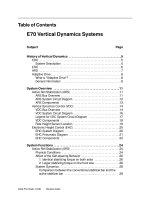
Technical Comparisons (E53 vs E70)
The E70 represents the logical development of the proportions of the E53. The vehicle's
external dimensions are bigger than those of the E53. The wheelbase has been length-
ened significantly, making the E70 appear more stable and lending it a sovereign
presence.
5
E70 Introduction
2933
4854
1644
1933
2197
1650
1062
859
1766
99
8
9
9
1
Specification E70 E53
Unladen weight (kg)
2,125 2,095
Length (mm)
4,854 4,667
Width (mm)
2,197 2,180
Height (mm)
1
,766
1
,707
Wheelbase (mm)
2,933 2,820
Track width, front (mm)
1
,644
1
,576
T
r
ack width, rear (mm)
1,650 1,576
Technical Data
6
E70 Introduction
Specification units
X
5 3.0i SAV
N52B30O1
X
5 4.8i
N62B48O1
Number of doors/seats
5/5 5/5
Vehicle length/width/height, unladen mm
4,854/1,933/1,728 4,854/1,933/1,728
Wheelbase/turning circle mm/m
2,933/12.8 2,933/12.8
Track width, front/rear mm
1,644/1,650 1,644/1,650
Load volume (DIN 70020) ltrs.
602-1,692 602-1,692
Fuel tank capacity ltrs
85 85
Unladen weight (DIN/EU) kg
2,085/2,160 2,215/2,290
Permissible total weight/payload kg
Permissible front/rear axle load kg
1,240/1,525 1,350/1,545
Permissible trailer load
braked 12%/8%
kg
2,300/2,700 2,300/2,700
Permissible trailer load,
un-braked/roof load
kg
750/100 750/100
Engine type/number of cylinders
6-cylinder in-line V-8 engine
Valves/cylinder
4 4
Engine management system
MSV80 ME9.2.3
Engine displacement
cm
3
2,996 4,799
Engine output/RPM bhp
260 @6600 350 @ 6300
Torque/RPM Nm
315 @ 3000 460 @ 3500
Compression ratio
10.7
t
o 1
10.5
t
o 1
F
uel type
R
ON 91-98
R
ON 91-98
T
r
ansmission
type (auto)
GA6HP19TU GA6HP26TU
Final drive ratio
4.44 3.91
7
E70 Introduction
Specification units
X5 3.0i SAV
N52B30O1
X5 4.8i
N62B48O1
Steering type/ratio
Rack and pinion/variable Rack and pinion/variable
Front brakes-diameter/thickness mm
Disc 332/30 Disc 365/36
Rear brakes-diameter/thickness mm
320/20 345/24
Air resistance (coefficient of drag) cd
0.341 0.351
Top speed (electronically limited)
130 150
Front tires
255/55 R18 H XL RSC 255/55 R18 H XL RSC
Rear tires
255/55 R18 H XL RSC 255/55 R18 H XL RSC
Front rims
8.5J x 18 LM 8.5J x 18 LM
Rear rims
8.5J x 18 LM 8.5J x 18 LM
Battery/location Ah
70/luggage comp 70/luggage comp
Alternator A/W
150/2,100 185/2,590
Ground clearance mm
215 215
Overhang, front/rear mm
859/1,062 859/1,062
Width (mirr
or to mirror)
mm
2,197 2,197
Rim offset mm
46 46
Nose w
eight
k
g
120 120
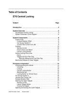
E70 Body Overview
The E70 bodyshell has a number of technical highlights. For example, the B-pillar
consists of tailor rolled blanks, which are hot formed and enable a high-strength weight
saving of 2 kg per vehicle.
This also increases performance in a crash. The torsional strength has been increased
from 23,500 Nm/° (E53) to 27,000 Nm/° (E70). The bodyshell played a key role in
achieving a rating of 5 stars in the NCAP crash test. Many reinforcements were made to
the front end, Bpillar and rear end. This involved using high strength steels.
8
E70 Introduction
Legend to graphic on next page.
9
E70 Introduction
Index Explanation Index Explanation
1
DX54D, DX56D, HC180BD, HC180YD
7
HC680C, HC540X
2
HC220BD, HC220YD
8
22MnB5
3
HC260BD, HC260YD
9
AlMg3Mn, AlMg4,5Mn0,4AC46000, AlMgSi
AlMg0,4Si1,2, AlSi10MgMn
4
HC300BD
10
Plastics
5
HC380LAD
11
Other
metals
6
HC420LAD
The body
structure is designed in line with the Euro NCAP front impact test, the Euro
NCAP pole test and the LINCAP side impact test as well as the IIHS side impact and
high-speed rear impact tests in the USA.
Wherever possible, all situations occurring outside of legal requirements, and intended to
ensure the protection of the passengers have been taken into consideration.
In an impact at
up to 15 km/h, the body structure remains undamaged. The separating
cuts for repair are outside the B-pillar. To prevent corrosion, the sill beam is dried.
10
E70 Introduction
See legend on
previous page
At the front end, a sheet metal shell design modeled on the E53 has been used, but with
a cast aluminum spring support. The advantages of this construction, in addition to the
weight saving of 7-8 kg, include the smaller dimensions and the improved force input
through different thicknesses and rib distribution.
In addition, the sheet metal shell design is easier to repair, as individual components can
be replaced.
Repair Solution
• Planned solution modeled on the E60
• The punched rivet connections are drilled out, and then a blind rivet is used per
punched rivet connection
• Repair adhesive: Betamate BM 2096
• Ensure corrosion protection (PVC coating).
11
E70 Introduction
Frontal Impact
In terms of passive safety, the developers of the E70 focused on developing an extremely
stable passenger cell, which offers the passengers a greater level of safety in a crash at
high speeds.
This was achieved by distributing the forces exerted on the structure over the engine
bracket and chassis to the passenger cell through several load paths, in order to keep the
load peaks low in the individual carrier structures.
Specifically, this means the consistent use of the lead path from the wheel to the sill
beam and distribution of the engine bracket loads to the A-pillar, sill beam and end-to-
end side member structures.
Regardless of the type of front impact, it was attempted to move the wheel in a straight
line backwards to the sill beam. This results in a massive load path from the
barrier/object hit through the wheel to the sill beam, which has been provided with a
strong additional profile for this purpose (attachment of lateral side members).
The engine bracket loads are routed from the bulkhead through the carrier support on the
lower bulkhead and the tunnel cover to both the A-pillar and the respective other side of
the vehicle. In addition, the carrier support on the lower bulkhead is also braced at the
back by the closing plate on the tunnel.
The connection between the engine bracket and the transmission carrier represents yet
another load path. This means profiles that were required anyway have been optimally
incorporated in achieving and increasing the performance.
12
E70 Introduction
To keep the load on the bulkhead and thus the height of the bulkhead intrusion generally
low, the engine bracket has been designed so that it buckles in a specific place and
triggers a deformation path. Loads that are routed through the wheel arch carrier
supports to the bodyshell are distributed to the A-pillar and through the wheel arch carrier
support reinforcement to the sill beam.
This reduces the impact on the A-pillar and minimizes backwards movement.
This design ensures, on the one hand, that the doors can still be opened even after high
crash loads, and, on the other hand, prevents the doors from opening independently
following overloading during the crash.
The end-to-end side members beneath the floorpan make a significant contribution to
the stability of the passenger cell. The bodyshell has been coordinated with the bumper
system in such a way that the loads occurring during low speed crashes are completely
absorbed by the bumper system.
As soon as a critical crash speed is exceeded, the engine bracket begins to deform from
the front. This behavior is the prerequisite for low repair costs.
13
E70 Introduction
Side Impact
In side impacts too, the bodyshell helps provide optimum protection of the passengers
against injury. This is achieved by the precisely coordinated behavior of the sheet metal
structure and the restraint system. The design of the E70 allows the B-pillar to remain as
straight as possible in every tested load case and to penetrate the vehicle uniformly.
The loads that occur are at their highest in the center of the B-pillar. To cope with this
and yet not dispense with the idea of lightweight construction, the B-pillar reinforcement,
which significantly influences the crash functionality, has been produced from a high-
strength material which also exhibits a much higher wall thickness in the middle area than
at the top and bottom ends due to the rolling process.
The rest of the load is then distributed through the vehicle's cross-member structures.
Thus, loads that occur above the base plate are routed to the opposite side of the vehicle
from the impact side via the seat cross-members. Beneath the base plate, various other
cross members perform this same function.
In the roof area the same role is performed by the roof mirror or, on the panorama roof
version, the roof system with its stiff side members and cross-members.
14
E70 Introduction
Rigidity
It was also possible to significantly improve
the rigidity of the vehicle while still satisfy-
ing the notion of lightweight construction
by using the deep-lying wheel arch carrier
supports, which are deflected to the
center of the vehicle and have a rigid
connection to the engine bracket.
Another potential for increasing torsional
strength was realized by connecting the
wheel arch carrier support with the
bumper cross member via the diagonal
supports. This means the torsional
strength of the entire front end of the E70
has been improved through new carrier
processes, without requiring more compo-
nents or adding weight.
It was also possible to significantly improve
the rigidity by using a closed torsion ring
around the D-pillar.
The torsion ring essentially consists of the
following components: rear roof brace, C-
pillar, lateral side members and the cross-
members in the base plate area.
Another feature used to increase the
torsional strength is the load-sharing,
wedged tailgate.
By applying tension to the hatch between
the D-pillars, the hatch shell, with its pro-
files, increases the rigidity.
15
E70 Introduction
Pedestrian Protection
In the E70, various measures have been taken towards pedestrian protection.
1. The aluminum bonnet has a flexible design in case of head impact.
2. The bonnet hinges have a disengaging mechanism in the direction of impact
3. The module carrier of the side panel module is made of plastic and is very flexible in
the direction of impact.
16
E70 Introduction
Index Explanation Index Explanation
1
Hood
3
Side panel module
2
Hood Hinge