Xe ô tô BMW X5 E70 SM 03c_E70 Energy Management
Bạn đang xem bản rút gọn của tài liệu. Xem và tải ngay bản đầy đủ của tài liệu tại đây (369.42 KB, 35 trang )
Initial P
rint
Dat
e: 10/06
Table of Contents
Subject Page
The Energy Circuit in the Vehicle . . . . . . . . . . . . . . . . . . . . . . . . . . . . . . .5
Power Management . . . . . . . . . . . . . . . . . . . . . . . . . . . . . . . . . . . . . . . . . . . .6
Idle Speed Boost . . . . . . . . . . . . . . . . . . . . . . . . . . . . . . . . . . . . . . . . . . . .6
Charging Voltage Target Value . . . . . . . . . . . . . . . . . . . . . . . . . . . . . . . . .6
Emergency Operation . . . . . . . . . . . . . . . . . . . . . . . . . . . . . . . . . . . . . . . . . . .7
APM Control System . . . . . . . . . . . . . . . . . . . . . . . . . . . . . . . . . . . . . . . . .7
Electric Load Reduction . . . . . . . . . . . . . . . . . . . . . . . . . . . . . . . . . . . . . .7
Fuel Consumption Reduction Measures . . . . . . . . . . . . . . . . . . . . . . . .8
Advanced Power Management . . . . . . . . . . . . . . . . . . . . . . . . . . . . . . . . . . .9
Energy Flow . . . . . . . . . . . . . . . . . . . . . . . . . . . . . . . . . . . . . . . . . . . . . . . . .9
Information Flow . . . . . . . . . . . . . . . . . . . . . . . . . . . . . . . . . . . . . . . . . . . .10
Diagnosis Information . . . . . . . . . . . . . . . . . . . . . . . . . . . . . . . . . . . . . . .11
Vehicle in Stationary Mode (terminal R and terminal 30) . . . . . . . . .12
Electric Loads in Stationary Mode . . . . . . . . . . . . . . . . . . . . . . . . . .12
Stationary Load Log-off . . . . . . . . . . . . . . . . . . . . . . . . . . . . . . . . . . .12
Terminal 30g and Terminal 30g_f . . . . . . . . . . . . . . . . . . . . . . . . . . .12
Terminal 30g and Terminal 30g_f relay . . . . . . . . . . . . . . . . . . . . . . . .14
Time-dependent Deactivation . . . . . . . . . . . . . . . . . . . . . . . . . . . . .14
Fault-dependent Deactivation . . . . . . . . . . . . . . . . . . . . . . . . . . . . . .14
Terminal 30g_f Relay Switch-on and off Conditions . . . . . . . . . .14
Continuous P
ositive . . . . . . . . . . . . . . . . . . . . . . . . . . . . . . . . . . . . . .15
General Measures . . . . . . . . . . . . . . . . . . . . . . . . . . . . . . . . . . . . . . . . . .16
Components . . . . . . . . . . . . . . . . . . . . . . . . . . . . . . . . . . . . . . . . . . . . . . . . . .17
Intelligent Battery Sensor (IBS) . . . . . . . . . . . . . . . . . . . . . . . . . . . . . . .17
Junction Box . . . . . . . . . . . . . . . . . . . . . . . . . . . . . . . . . . . . . . . . . . . . . . .19
Engine Management (Power Management) . . . . . . . . . . . . . . . . . . . .20
Transport Mode . . . . . . . . . . . . . . . . . . . . . . . . . . . . . . . . . . . . . . . . . . . . . . .21
Closed-circuit Current . . . . . . . . . . . . . . . . . . . . . . . . . . . . . . . . . . . . . . . . . .23
Electrical System and Battery Diagnosis . . . . . . . . . . . . . . . . . . . . . . . . .24
Energy Management - Diagnosis in Vehicle . . . . . . . . . . . . . . . . . . . .25
Energy History Memory . . . . . . . . . . . . . . . . . . . . . . . . . . . . . . . . . . . . . .27
Memory Cycle . . . . . . . . . . . . . . . . . . . . . . . . . . . . . . . . . . . . . . . . . . .27
Driving Profile and Stopped Profile . . . . . . . . . . . . . . . . . . . . . . . . .27
Sleep Blockers . . . . . . . . . . . . . . . . . . . . . . . . . . . . . . . . . . . . . . . . . . . . .28
Bus Wake-ups . . . . . . . . . . . . . . . . . . . . . . . . . . . . . . . . . . . . . . . . . . .28
Intact V
ehicle . . . . . . . . . . . . . . . . . . . . . . . . . . . . . . . . . . . . . . . . . . . . . . .29
E70 Energy Management
R
e
vision Dat
e:
Subject Page
Defective Vehicle . . . . . . . . . . . . . . . . . . . . . . . . . . . . . . . . . . . . . . . . . . .30
Data Record . . . . . . . . . . . . . . . . . . . . . . . . . . . . . . . . . . . . . . . . . . . . . . . .33
Sleep Blockers . . . . . . . . . . . . . . . . . . . . . . . . . . . . . . . . . . . . . . . . . . .33
Number of bus wake-ups, driving profile/stopped profile . . . . . .33
Bus Wake-up IDs . . . . . . . . . . . . . . . . . . . . . . . . . . . . . . . . . . . . . . . . . . .34
Data Record Storage . . . . . . . . . . . . . . . . . . . . . . . . . . . . . . . . . . . . . .34
Ring Memory . . . . . . . . . . . . . . . . . . . . . . . . . . . . . . . . . . . . . . . . . . . . . . .35
Subject Page
BLANK
PAGE
4
E70 Energy Management
Energy Management
Model: E70
Production: From Start of Production
After completion of this module you will be able to:
• Locate and Identify Energy Management System Components
• Understand E70 Energy Management
As in the current models, an energy management system is used in the E70 to ensure
balanced energy management in the vehicle.
The energy management functions are integrated in the power management system
that is implemented in the form of software in the engine control unit.
5
E70 Energy Management
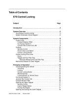
The Energy Circuit in the Vehicle
Inde
x
Explanation
1
Engine
2
Alternator
3
Int
elligent
B
att
ery Sensor
4
Battery
5
Junction Box
6
Electrical load (i.e. headlights)
7
Engine management
with int
egr
ated power management
Power Management
The power management establishes the control processes in the area of energy
management of our vehicles.
A basic distinction is made between two types of power management:
• Basic Power Management (BPM)
• Advanced Power Management (APM)
Only the advanced power management APM is used in the E70.
In addition to the main functions of the basic power management, idle speed and of
charging voltage target value, this system includes the following expanded functions:
• Electric load reduction
• Electric load shut-down
• Vehicle systems diagnosis
• Battery diagnosis
Idle Speed Boost
Despite the alternator operating at maximum,
on gasoline engine vehicles the idle speed is
increased by up to 200 rpm as soon as
current is drawn from the battery.
Charging Voltage Target Value
The charging voltage at the alternator is
controlled dependent on the temperature.
The temperature value is made available by the
Intelligent Battery Sensor (IBS).
The power management uses this value as the
input variable for calculating the battery tem-
perature. With the aid of a calculation model,
the specified charging voltage is set based on
the battery temperature.
This information is sent to the alternator via
the Bit-serial Data Interface (BSD).
6
E70 Energy Management
Index Explanation
1
Model- based batt
ery temperature of
8 degrees Celsius
2
Model- based battery
temperature of
15 degrees Celsius
Emergency Operation
The APM makes use of emergency operation functions when there is a break in the BSD
interface. In this case, the alternator voltage is set to a constant 14.3 V. A fault code
"Communication BSD" is entered in the fault code memory of the engine management.
APM Control System
Electric Load Reduction
When the vehicle is equipped with APM (advanced power management), in addition to
increasing the idle speed and the specified charging voltage, the output of various electric
loads can be reduced or the loads can be switched off in order to reduce the power
consumption in critical situations.
The electric loads are shut down only under the following two conditions:
• Battery charge status in critical range
• Alternator fully utilized
7
E70 Energy Management
Index Explanation
1
Advanced Power Management
2
Idle Speed Boost
3
Engine
4
Charging voltage target value
5
Alternator
6
Electrical load reduction
7
Electrical loads
8
Electrical system and battery diagnosis
9
BMW diagnostic system
10
Intelligent battery sensor
11
Battery data
Fuel Consumption Reduction Measures
The following measures are activated under these preconditions:
Note: All measures are implemented in the specified order.
8
E70 Energy Management
Sequence Function Operation Control Unit
1
Rear Window Clocking IHKA
2
Seat Heating, rear compartment Stage 2 FKA
3
Electrical auxiliary heater, rear compartment 75 % FKA
4
Seat heating, front Stage 2
SMBFA
SMBF
JB
5
Seat heating, rear compartment Stage 1 FKA
6
Electrical auxiliary heater, rear compartment 50 % FLA
7
Seat heating, front 50 %
SMBFA
SMBF
JB
8
Electrical auxiliary fan, 3rd row seating 50 % IHKA
9
Heater blower 75 % IHKA/FKA
10
Electrical auxiliary heater, rear compartment 25 % FKA
11
Steering wheel heating OFF FRM/JB
12
Electrical auxiliary heater, rear compartment OFF FKA
13
Mirror heating OFF FRM/JB
14
Active seat OFF
SMFA
SMBF
15
Steering wheel heating OFF IHKA
16
Electrical auxiliary
fan, 3rd row seating
OFF IHKA
17
Seat
heating, front
OFF
SMF
A
SMBF
JB
18
Seat heating, rear compartment OFF FKA
19
R
ear windo
w
OFF IHKA
20
Heater blower 50 % IHKA/FKA
21
Heat
ed windshield
OFF
SMF
A
SMBF
22
Heat
er blower
25 % IHKA
/FKA
Advanced Power Management
Energy Flow
During vehicle operation, the mechanical energy of the engine is converted by the
alternator into electrical energy and made available to the electric loads. The electric
loads receive their power supply mainly via terminal 30g and via terminal 30g_f.
Certain electric loads are also still supplied directly by terminal 30 or by terminal R.
For example, the anti-theft alarm system (DWA) must still remain active when the
vehicle is parked.
9
E70 Energy Management
Index Explanation Index Explanation
1
Electric loads
5
Vehicle battery
2
Drive motor
6
Control units
3
Alternator
KL30g
Terminal 30, switched
4
Intelligent Battery Sensor
KL30g_f
Terminal 30 switched, fault dependent
Information Flow
The calculations necessary for controlling the energy balance take place in the power
management. The idle speed and charging voltage are regulated while the engine is
running. The power intake of electric loads with relatively high power consumption is
reduced or the loads are switched off as required.
Certain electric loads can be switched off when the engine is stationary. This takes place
either time-controlled via the CAS and the terminal 30g relay or in response to electrical
faults via the engine control, junction box and the terminal 30g_f relay.
10
E70 Energy Management
Index Explanation Index Explanation
1
Electrical loads
4
Intelligent battery sensor
2
Engine
5
Vehicle battery
3
Alt
ernat
or
6
Contr
ol units
Diagnosis Information
The control units for the engine management, junction box and footwell module provide
various information for the purpose of realizing effective diagnosis. Information relating to
the status of the vehicle battery is stored in the engine management (engine control).
Information on the functional sequences in the various bus systems is stored in the
junction box. The BMW diagnosis system can access and evaluate this information.
The BMW diagnosis system features an evaluation software that facilitates assessment of
the history values and indicates the cause of problems as the result.
This result must be assessed by a technician in order to find the correct cause of the
fault.
11
E70 Energy Management
Index Explanation Index Explanation
1
BMW Diagnostic system
4
Bus systems
2
Engine management
5
Junction box control unit/Footwell module
3
V
ehicle battery with IBS
Vehicle in Stationary Mode (terminal R and terminal 30)
Electric Loads in Stationary Mode
Certain electric loads may be active even when the closed-circuit current monitoring
facility of the power management is already in operation. This is necessary for various
reasons:
• Legally required electric loads, e.g. side lights, hazard warning system
• Convenience for the customer, e.g. radio function, telephone
These electric loads must be excluded from the closed-circuit monitoring system in order
to avoid misinterpretation in the power management. For this purpose, these electric
loads must log in with the power management.
In turn, the power management recognizes the activity and accepts the higher power
consumption when the systems are deactivated, the corresponding control units log off
from the power management.
Stationary Load Log-off
The power management in the engine control can send a request to switch off the active
electric loads in stationary mode depending on the battery charge status and the start
capability limit. As a result, the stationary loads must deactivate their functions
irrespective of the terminal status and must reach their closed-circuit current within 5
minutes. Legally required electric loads are excluded from this function.
Terminal 30g and Terminal 30g_f
The E70 is equipped with various relays for switching off the power supply to most
control units. There are two terminal 30g relays in the front and rear power distribution
boxes. The terminal 30g_f relay in the rear power distribution box is required for the
following optional equipment:
• Multi-audio system controller
• Car communication computer
• Comfort Access
• Instrument cluster
• Telephone US/telephone preparation US
12
E70 Energy Management
13
E70 Energy Management
The relays are controlled by following control units:
• Terminal 30g_f - activation by the junction box control unit
The calculation necessary for activating the terminal 30g_f relay takes place in two
control units. The following activities are monitored in the junction box control unit:
– Invalid wake-up procedures within the bus systems
– Sleep blockers (control units that constantly keep the bus systems active)
The battery values are constantly read and evaluated in the engine control unit. The relay
is also switched off when the starting capability limit of the vehicle battery is reached.
• Terminal 30g - activation by the CAS
Description Explanation
KL15
Ignition (position 2)
KL R
Accessory (position 1)
KL 30
B+ Constant
KL 30g
B+, time dependent
KL 30 g_f
B+, fault dependent
Terminal 30g and Terminal 30g_f relay
Time-dependent Deactivation
The terminal 30g relay switches off the connected electric loads after 30 minutes.
The after-running time is extended to 60 minutes if a telephone or auxiliary heating
system is installed in the vehicle. The terminal 30g relay is activated by the CAS.
Fault-dependent Deactivation
The terminal 30g_f relay is activated by the junction box control unit and switches off the
connected electric loads if a fault occurs. The terminal 30g_f relay is a bistable relay.
Each switching status is retained even when no power is applied.
Terminal 30g_f Relay Switch-on and off Conditions
The terminal 30g_f relay is switched on and off under the following conditions.
Terminal 30g_f ON:
• Vehicle unlocked or
• Terminal R or
• Change in status_contact_rear_hatch or change in status_door_contact_FAT/BFT/
FATH/BFTH
Terminal 30g_f reset takes place:
• On reaching the upper start capability limit (start capability limit plus buffer for
discharging in stationary mode).
• When the vehicle does not assume sleep mode for 5 minutes (codeable) after
sending the power down command (command for all control units to assume sleep
mode) without a switch-on condition being applied.
• When the vehicle is woken 10 times after switching off terminal 30g without a
switch -on condition being applied. An after-running period of 2 minutes applies in
this case.
Terminal 30g_f OFF:
• Bus activity 10 minutes after reset without a switch-on condition being applied.
• Vehicle is woken 5 times without a "switch on" condition being applied.
• "Signal OFF" received. Terminal 30g_f relay is switched off after 2 minutes.
The
terminal 30g_f relay is a bistable relay and is always in the ON state under normal
conditions. It switches off the connected electric loads only in the case of fault. Once
the terminal 30g_f relay has been switched off, one of the switch-on conditions is
necessary
in order to switch it on again.
14
E70 Energy Management