Xe ô tô BMW X5 E70 SM 07a_E70 Information and Communication
Bạn đang xem bản rút gọn của tài liệu. Xem và tải ngay bản đầy đủ của tài liệu tại đây (372.85 KB, 18 trang )
Table of Contents
E70 Information and Communication
Technology (IKT)
Subject
Page
Introduction . . . . . . . . . . . . . . . . . . . . . . . . . . . . . . . . . . . . . . . . . . . . . . . . . .3
Information and Communication Technology (IKT) . . . . . . . . . . . . . . . . . .3
Navigation Systems . . . . . . . . . . . . . . . . . . . . . . . . . . . . . . . . . . . . . . . . . . . . .3
Voice Activation Systems . . . . . . . . . . . . . . . . . . . . . . . . . . . . . . . . . . . . . . . .4
Telephone Systems . . . . . . . . . . . . . . . . . . . . . . . . . . . . . . . . . . . . . . . . . . . . .4
Telecommunication Services . . . . . . . . . . . . . . . . . . . . . . . . . . . . . . . . . . . . .5
Bus System Overview . . . . . . . . . . . . . . . . . . . . . . . . . . . . . . . . . . . . . . . . . .6
Components . . . . . . . . . . . . . . . . . . . . . . . . . . . . . . . . . . . . . . . . . . . . . . . . .10
IKT Component Locations . . . . . . . . . . . . . . . . . . . . . . . . . . . . . . . . . . . . . .10
TCU with “Professional” Radio System Circuit Diagram . . . . . . . . . . .15
TCU with “Professional” Radio and Navigation Circuit Diagram . . . . .16
Signals and Functions . . . . . . . . . . . . . . . . . . . . . . . . . . . . . . . . . . . . . . . . .18
Initial Print Date: 10/06
Revision Date:
Information and Communication Technology
Model: E70
Production: From Start of Production
After completion of this module you will be able to:
• Describe the Information and Communication System (IKT) used on the E70.
• Identify the components that make up the Information and Communication
System (IKT).
2
E70 Information and Communication Technology
Introduction
Information and Communication Technology (IKT)
IKT comprises systems that inform or entertain the driver and other occupants.
Depending on equipment configuration, the IKT also serves the purpose of making available servicing-relevant data and sending messages in the case of emergency.
This Product Information provides an overview of the IKT topics. The components available at the time of the market launch are described with the help of the vehicle outline
diagram and the bus overview.
With the E70, a fiber optics-based bus is also used for data transmission in information
and communication applications IKT in the BMW X5.
The MOST (Media Oriented System Transport) is already known from the following
BMW vehicles:
• BMW 7 Series (E65, E66)
• BMW 6 Series (E63, E64)
• BMW 5 Series (E60, E61)
• BMW 3 Series (E90, E91, E92)
Navigation Systems
Map navigation (Professional navigation system) based on the Car Communication
Computer (CCC) is provided in the E70. The functions correspond with the areas already
known in the E60, E61, E63, E64, E90, E91 and E92.
Via the voice input, the CCC supports the entry of whole words for a country, town and
street. It is still also possible to spell the destination.
For the market launch of the E70 in the USA, the (RTTI) traffic warning system (Real
Time Traffic Information) is provided. The service is controlled by the "Traffic information
for navigation"option and is currently included in the range of functions of the
"Professional navigation system" option.
RTTI is transferred in the form of a data stream from particular FM stations. The data is
received from the CCC FM tuner, evaluated and made available for the navigation system. In the navigation map, traffic issues are indicated by symbols. The traffic issues are
also available in a list. The list entries are then sorted by the current distance between
the vehicle and the traffic issue. If the traffic issue is on the current route, there is a voice
output.
3
E70 Information and Communication Technology
Voice Activation Systems
The High and Basic voice activation systems already familiar in the E60, E61, E63, E64,
E90, E91 and E92 are available. The High voice activation system is used in the CCC.
The Basic voice activation system allows operation of the telephone functions and is
used in the Telematics Control Unit (TCU).
Telephone Systems
The following telephone systems will be available:
• "Complete mobile phone station" option.
• "Carphone station"option.
"Telephone station" option comprises:
• Wiring harness to connect the Telematics Control Unit TCU, base plate, Bluetooth
antenna, SOS antenna, SOS speaker, microphone and emergency call button with
emergency call indicator lamp.
• Roof aerial with telephone aerial.
4
E70 Information and Communication Technology
Telecommunication Services
The following well-known services from BMW ASSIST are available:
• Emergency call
– Manually using the emergency call button
– Automatically by airbag triggering
• Roadside assistance
– Manually via the BMW ASSIST menu
• Service request
– Manually via the BMW ASSIST menu
• BMW customer relations
– Manually via the BMW ASSIST menu
• Auto request
– Automatic service request, triggered by the instrument cluster when
CBS warning messages appear
– Activated in the BMW ASSIST menu
• Stolen Vehicle Recovery
– Remote service, triggered on behalf of the customer by the ATX service provider.
Note: All services named here are available without restriction for all equipment specifications.
With the start of series production of the E70, the following new services are also
planned:
• Remote Door Unlock
– Unlocking of the vehicle, triggered on behalf of the customer by the ATX service
provider.
• Concierge service
– Download of points of interest, such as filling stations, restaurants, hotels, etc.
– The service is started by the customer in the BMW ASSIST menu.
Note: Both services require the "Complete mobile phone station USA"option
to be fitted. If the navigation system is fitted, the concierge service data
can be accepted for destinations.
5
E70 Information and Communication Technology
6
E70 Information and Communication Technology
VSW
CAS
FZD
RDC
RLSS
RDC_SEN
CA
TE06-1677
2x
SMC
2x
ASP
FRM
SBFA
ACSM
SMBF
RFK
SMFA
AHM
HKL
SVFA
4x/5x
PDC
SINE
HB3SR
FLA
FKA
SH
EHC
IHKA
Kombi
ZH
6x/10x/13x
WUP
1
OC3
SVBF
4x
TAGE
Crash_ Signal
MOST WUP
HIFI
RSE
FD
CON
CID
FlexRay
K-CAN
MOST
LR
F-CAN
D-CAN
SDARS
TCU
TOP-HIFI
DVD
PT-CAN
CDC
CHAMP
CCC
FS
DAB
K-NAV
C-NAV
LoCAN
BSD
LIN-Bus
(protokoll)
K-Bus
IBOC
J-NAV
VM
HUD
JB
EDC SHL
EDC SVL
EKP
VGSG
EMF
ARS
AL
DSC
SZL
DSC_SEN
WUP
VDM
1
EDC SHR
EDC SVR
EGS
GWS
VVT
DDE
DME
GSG
IBS
EWP
QLT
1
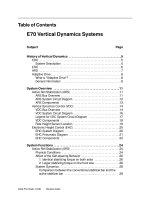
Bus System Overview
Legend for Bus System Overview
Index
ACSM
AHM
AL
ARS
ASP
CA
CAS
CCC
CDC
CHAMP
CID
C-NAV
CON
DAB
DDE
DME
DSC
DSC_SEN
DVD
EDC SHL
EDC SHR
EDC SVL
EDC SVR
EGS
EHC
EKP
EMF
EWP
RD
FKA
FLA
FRM
FZD
GSG
GWS
HB3SR
HiFi
HKL
HUD
IBOC
IBS
Explanation
ACSM control unit
Trailer module
Active steering system
Active anti-roll bar
Outside mirror
Comfort Access
Car access system
Car communication computer
CD changer
Central Head Unit and Multimedia Platform
Central information display
China navigation (will be introduced at a later date)
Controller
Digital audio broadcasting (will be introduced at a later date)
Digital diesel electronics
Digital engine electronics
Dynamic stability control
DSC Sensor
DVD changer (will be introduced at a later date)
Electronic Damper Control satellite, rear left
Electronic Damper Control satellite, rear right
Electronic Damper Control satellite, front left
Electronic Damper Control satellite, front right
Electronic transmission control unit
Electronic Height Control
Electric fuel pump
Electromechanical parking brake
Electric water pump
Rear display
Rear heater/air-conditioning system
High beam assistant
Footwell module
Roof function center
Preheater control unit
Gear selection switch
Heating/ventilation, 3rd row of seats
HiFi amplifier
Tailgate lift
Head-up display
High Definition Radio (will be introduced at a later date)
Intelligent battery sensor
7
E70 Information and Communication Technology
Legend for Bus System Overview (Cont.)
Index
Explanation
IHKA
Integrated automatic heating/air conditioning system
JB
Junction box control unit
J-NAV
Japan navigation (will be introduced at a later date)
K-NAV
Korea navigation (will be introduced at a later date)
Kombi
Instrument cluster
OC3
Seat occupancy detector mats, US
PDC
Park distance control
QLT
Quality level temperature sensor
RDC
Tire pressure control
RDC_SEN
Tire pressure control sensor
RFK
Reversing camera
RLSS
Rain/driving light solar sensor
RSE
Rear seat entertainment
SBFA
Driver's switch cluster
SDARS
Satellite tuner
SH
Auxiliary heater
SINE
Tilt alarm sensor siren
SMBF
Passenger's seat module
SMC
Stepper motor controller
SMFA
Driver's seat module
SVBF
Front passenger seat adjustment
SVFA
Driver seat adjustment
SZL
Steering column switch cluster
TAGE
Electronic outer door handle module
TCU
Telematics Control Unit
TÖNS
Thermal oil level sensor
TOP-HIFI
Top-HiFi amplifier
VDM
Vertical Dynamic Management (central control unit for Electronic Damper Control)
VGSG
Transfer box control unit
VM
Video module
VSW
Videoswitch
VVT
Variable valve gear
ZH
Electric auxiliary heater
8
E70 Information and Communication Technology
NOTES
PAGE
9
E70 Information and Communication Technology
Components
IKT Component Locations
10
E70 Information and Communication Technology
Legend for IKT Component Locations
Index
Explanation
Index
Explanation
1
Broadband speaker or medium-range loudspeaker Left-hand front door
21
Aerial amplifier with diversity module
2
Tweeter, left-hand front door
22
Tweeter, right-hand rear D-post
3
SOS speaker
23
Medium-range loudspeaker, right-hand rear Dpost
4
MOST direct access
24
Heated rear window blocking circuit with suppressor filter for additional brake light
5
Multifunction steering wheel (MFL)
25
Tweeter, left-hand rear D-post
6
Mid-range speaker, front center
26
Medium-range loudspeaker, left-hand rear D-post
7
Tweeter, front center
27
Satellite tuner (SDARS)
8
Central information display (CID)
28
High Definition Radio (IBOC)
9
Roof function center (microphone and emergency call button)
29
Audio amplifier (HiFi or Top-HiFi)
10
CD changer (CDC)
30
Telematics Control Unit (TCU)
11
Head Unit
31
SOS antenna
12
Snap-in adapter
32
Head phone connectors
13
Tweeter, right-hand front door
33
Rear seat entertainment (RSE)
14
Broadband speaker or medium-range loudspeaker, right-hand front door
34
Audio jack (AUX-In)
15
Rear display (RD)
35
Bluetooth antenna
16
Central bass speaker, right
36
Controller
17
Radio remote control (RRC) for rear seat entertainment
37
Broadband speaker or medium-range loudspeaker, left-hand rear door
18
Tweeter, right-hand rear door
38
Central bass speaker, left
19
Broadband speaker or medium-range loudspeaker, right-hand rear door
39
Tweeter, eft-hand rear door
20
Roof aerial (satellite tuner, GPS, telephone)
11
E70 Information and Communication Technology
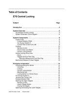
Telematics Control Unit with CHAMP
12
E70 Information and Communication Technology
Telematics Control Unit with CCC
13
E70 Information and Communication Technology
TCU Input/Output Legend
Index
Explanation
Index
Explanation
Microphone, emergency call button with emer-
1
Head Unit (CCC/CHAMP)
10
gency call indicator lamp in the
roof function center
2
Multifunction steering wheel (MFL)
11
SOS speaker
3
Central information display (CID)
12
Bluetooth antenna
4
Wheel speed sensor
13
Snap-in adapter with mobile phone
5
Roof aerial (GPS)
14
Roof aerial (mobile phone)
6
Telematics Control Unit
15
Car Access System (CAS3)
7
Advanced Crash Safety Module (ACSM2)
16
Instrument cluster
8
SOS antenna
17
Audio speaker
9
Roof aerial (TCU)
18
Controller
The legend above applies for the two preceding input/output diagrams. The first one
shows the 'Professional' radio option, the second shows the 'Professional' with navigation
system.
Note: In the US version, CHAMP is fitted as the “Professional” radio and in the
European version, the M-ASK.
The difference between the two items of equipment lies in the activation of the GPS and
wheel speed signals. With the 'Professional' radio, both signals are sent to the Telematics
Control Unit TCU. With the navigation system, both signals are sent to the Car
Communication Computer CCC.
Communication between the mobile phone and the Telematics Control Unit takes place
via the Bluetooth interface.
14
E70 Information and Communication Technology
TCU with “Professional” Radio System Circuit Diagram
19
2
CID
18
K-CAN
FS
Kl. 30g
LVDS
1
MOST
Kl. 58g
Kl. 30g_f
CHAMP
4
3
Kl. 30g
17
5
16
MOST
WUP
CAS3
Mic +
Mic -
6
SOS LED
SOS
7
Crash_Signal
ACSM2
Cradle_Key+
15
11
Cradle_On
9
Grundplatte
10
BT
8
14
HF + UB
Kl. 30g
12
SOS
GPS
Tel
Tel
MOST
TCU
13
15
E70 Information and Communication Technology
TCU with “Professional” Radio and Navigation Circuit Diagram
16
E70 Information and Communication Technology
Legend for Professional Radio/with Navigation Circuit Diagrams
Index
Explanation
Index
Explanation
1
Head Unit
11
Broadband speaker right-hand rear door
2
Central information display
12
Roof aerial (TCU, mobile phone, GPS)
3
Controller
13
Telematics Control Unit
4
Broadband speaker right-hand front door
14
SOS antenna
5
Central bass speaker, right
15
Broadband speaker left-hand rear door
6
gency call button with emergency call indi-
16
Car Access System (CAS3)
Roof function center (microphone, emercator lamp)
7
Advanced Crash Safety Module
17
Central bass speaker, left
8
Base plate
18
Broadband speaker left-hand front door
9
Snap-in adapter with mobile phone
19
SOS speaker
10
Bluetooth antenna
MOST
MOSTWUP
Vehicle wake-up signal from the
LVDS
Mic+
SOS
LED
Cradle
Key+
HF
Media Orientated System Transport (digital
bus)
FS
MOST direct access
Crash_ Signal
Activation of emergency signal
Microphone, positive
Mic-
Microphone, negative
Emergency call indicator lamp
SOS
Emergency call signal
Handsfree button
Cradle On
High frequency signal
UB
Telematics Control Unit
Low voltage differential signal
(digital RGB signal)
ON signal for the charger electronics in the
snap-in adapter
Power supply
17
E70 Information and Communication Technology
Signals and Functions
MOST Signals on the Control Unit TCU
In/out
Signal
Source/sink
In
GPS signals
Function
> GPS aerial
> CCC
Position data
In
Control signals
> Head Unit
Telephone directory, establishing/ending connection,answering call, emergency call,
terminal control,
Out
Audio signals
> Head Unit
Audio signals, call recipient
BMW ASSIST
Out
Audio signals
> Head Unit
Audio signals, call recipient
mobile phone
Note: The legends apply for the two previous system circuit diagrams.
Thanks to the improved overview, the telephone systems with the stereo systems are
shown. The HiFi system is standard equipment in the US version. For more information
about these systems, see the "E70 audio systems" Product Information.
Depending on the equipment, the TCU is supplied with power via terminal 30g or terminal 30g_f. A power supply via terminal 30g_f is necessary for provision of the BMW
ASSIST services:
• Remote Door Unlock Opening the vehicle doors for servicing
• Stolen Vehicle Recovery
The implementation of the Remote Door Unlock service is carried out via the (MOST)
WUP signal. The signal is used to wake up the vehicle. The (TCU) reacts to a call from the
provider, performed in the customer order. The (TCU) sends a signal via the (MOST)
WUP line to the Car Access System (CAS3). The (CAS3) then wakes up the vehicle.
The CHAMP receives the terminal 58g (lighting) signal via fixed wiring. The CCC receives
this signal via the K-CAN.
The eject button on the base board does not receive a signal from terminal 58g. The button is not illuminated.
18
E70 Information and Communication Technology