TÀI LIỆU BIẾN TẦN DELIXI
Bạn đang xem bản rút gọn của tài liệu. Xem và tải ngay bản đầy đủ của tài liệu tại đây (2.62 MB, 114 trang )
To the user
To the user
——Notices of Onsite Installation and Operation
Respectful User:
Thanks for your selection of CDI inverter manufactured by Delixi Hangzhou Inverter Co., Ltd.
In order that you can better use the product, please pay attention to the following:
1.After installed and commissioned, fasten the components, especially connecting bolt of the
line, which shall cause fire accident due to heat at the connection if not fastened.
2.Design of installation on the site should be reasonable to maintain excellent ventilation.
3.In and out lines of the inverter should not be connected reversely. Otherwise, it shall lead to
inverter explosion.
4.Starting and stopping the motor directly by power-on and power-off the main circuit of the
inverter shall cause frequent jumping faults to the inverter.
5.When selecting inverter type, configure the inverter as per actual load power (load working
current). When there is heavy load, type selection can be magnified by 1 to 2 shifts. Smaller type
shall cause overcurrent or overload jumping faults to the inverter.
6.Protection level of the inverter is IP20, that is, it can prevent a foreign matter with a diameter
of 12.5mm or greater from completely entering, without waterproof function.
7.Inverter if stored for more than half a year should be powered with a voltage regulator to
increase voltage gradually. Otherwise, there is danger of electric shock and explosion.
8.If line connecting the inverter to the motor exceeds 50m, it is required to add AC output
inductor. Otherwise, the inverter and the motor are in danger of damage.
In order that you can use the product safely for a long time, you need to carefully inspect the
product, regularly power off it to clean and maintain. For any trouble in process of inspection, please
notify us by phone or mail. Our service hotline is 0571-85243785. We shall send professional to your
site as per your trouble to assist you in solving the trouble and ensure the product is operated safely
and reliably.
1
To the user
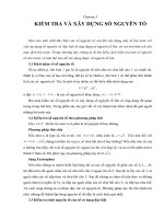
Common connection diagrams:
Figure 1: External stop/start,
adjusting speed by external
Figure 2: frequency control by
up/down terminals
potentiometer
2
Figure 3: PID control for water
Figure 4: PID control for water
supply at permanent pressure
supply at permanent pressure
(pressure transmitter)
(transmissible pressure gauge)
To the user
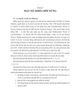
Figure 5: Inverter Multi-speed Control
Figure 6: Inverter output at 4-20mA
Figure 7: 3-line maintaining control mode
3
Contents
Foreword ................................................................................................................................... VI
Chapter 1 Safety Operation and Notices ...................................................................................... 1
1.1 Examination and Acceptance ................................................................................................. 1
1.2 Precautions for safe operation................................................................................................ 2
Chapter 2 Product Information .................................................................................................... 4
2.1 Nameplate data and naming rule............................................................................................ 4
2.2 Technical Specifications ........................................................................................................ 5
2.3 CDI9200 Inverters ................................................................................................................. 6
2.4 Appearance and installation dimension .................................................................................. 7
2.5 Routine maintenance ........................................................................................................... 10
Chapter 3 Installation and Connection of Inverter ..................................................................... 12
3.1 Installation of front cover and number keyboard ................................................................. 12
3.1.1 Installation of the Front Cover .......................................................................................... 12
3.1.2 Installation of the Digital Operation Keyboard ................................................................. 12
3.2 Selection of Installation Area and Space .............................................................................. 13
3.3 Wiring of Peripherals and Optional Parts ............................................................................. 15
3.4 Wiring of the Main Circuit .................................................................................................. 16
3.4.1 Wiring Diagram of the Main Circuit and Precautions ....................................................... 16
3.4.2 Precautions for Wiring the Input Side of the Main Circuit ................................................ 18
3.4.3 Precautions for Wiring the Output Side of the Main Circuit ............................................. 19
3.4.4 Cables for the 380V-level Main Circuit and Tables for Supporting Peripherals: ............... 21
3.5 Connection of control circuit ............................................................................................... 22
3.5.1 Terminal arrangement and connection diagram of control circuit ..................................... 22
3.5.2 Function of control circuit termina: .................................................................................. 24
3.6 Grounding ........................................................................................................................... 26
Chapter 4 Keyboard Operation and Running ............................................................................. 26
4.1 Selection of operating mode ................................................................................................ 27
4.2 Test run and inspection ........................................................................................................ 27
4.2.1 Precautions and Examination Prior to Trial Operation ...................................................... 27
4.2.2 Trial Operation ................................................................................................................. 27
4.2.3 Operating inspection ......................................................................................................... 27
4.3 Operating method of keyboard ............................................................................................ 28
4.3.1 Keystroke and function ..................................................................................................... 28
4.3.2 Display Mode ................................................................................................................... 30
4.3.3 Method of “check/set parameter” (via number keyboard) ................................................. 31
4.3.4 Frequency setting of keyboard .......................................................................................... 32
Chapter 5 Tables of Function Parameters .................................................................................. 33
I
Contents
Chapter 6 Function Instructions ................................................................................................. 48
6.1 Sort P00 Basic function parameter....................................................................................... 48
6.2 Sort P01 Secondary function parameter ............................................................................... 58
6.3 Sort P02-Input/output terminal and multi-speed running function ....................................... 66
6.4 Sort P03 ............................................................................................................................... 78
6.5 Sort P04 Other function parameter ...................................................................................... 81
6.6 Sort P05 Display functional parameter ................................................................................ 89
Chapter 7 Removing Faults ....................................................................................................... 90
7.1 Fault Diagnosis and Elimination .......................................................................................... 90
7.2 Motor Faults and their Elimination ...................................................................................... 91
7.3 Motor fault and exclusion measure ...................................................................................... 92
Appendix 1 Regular Maintenance and Inspection Methods ....................................................... 93
Appendix 2 Guides on Selection of Options .............................................................................. 95
A2.1 Alternating Current Reactor ACL ..................................................................................... 95
A2.2 Direct Current Reactor DCL ............................................................................................. 96
A2.3 Radio Noise Filter............................................................................................................. 96
A2.4 Remote Control Keyboard ................................................................................................ 97
A2.5 Regenerative Brake Unit and Regenerative Brake Resistors ............................................. 97
A2.6 Current Leakage Protection Circuit................................................................................... 98
Appendix 3 Instructions for Remaking Injection Machine ........................................................ 99
A3.1 Main circuit terminal connection diagram ........................................................................ 99
A3.2 Connection method of main electric circuit for frequency conversion and energy saving
modification of injection molding machine ............................................................................... 99
A3.3 Instructions for Connection method of transition slab: ................................................. 100
A3.4 Adjustment of main parameter: ....................................................................................... 101
II
Foreword
Foreword
Thank you for choosing CDI9200 Series Frequency Conversion Governor manufactured by
DELIXI (Hangzhou) Inverter Co.,Ltd.
Before using it, please read this manual carefully so as to guarantee correct operation. Erroneous
operation might result in malfunction, faults or shortened life span of the equipment, or even personal
injury. Therefore, users are advised to read carefully this manual and abide by it during operation.
The manual is a standard attached document. Please keep it for maintenance and repair in the future.
Aside from operation instructions, this manual also presents some wiring diagrams for your
reference. If you have any difficulty or special demands for using the inverter, please contact our
offices or distributors. You may also contact the customer service centre of our head office for our
quality service. The manual noted that its content might change without further notice.
Please confirm following content during unpackaging:
1. If the product is damaged during process of transportation, if parts are damaged and
dropped, or if main body is bruised.
2. If rated value marked on nameplate is consistent with your order requirement, or if
there are ordered unit, acceptance certificate, operation manual and guarantee shed in package.
The Company strictly complies with quality system during production and packaging, for any
inspection miss, please contact our Company or supplier for settlement.
People should not reprint,
transmit, and use the
manual or content relating
to it without written
permission of the Company,
who will assume legal
responsibility for damage
caused in violation of the
item.
III
Chapter 1 Safety Operation and Notices
Chapter 1 Safety Operation and Notices
Please read the manual carefully before install, operate, maintain or check CDI9200 series
converter.
To protect yourself, the equipment, and the property from any possible harm, please do read this
chapter before using our CDI9200 Series Inverters. Precautions relevant to operation safety are
categorized as “warning ” and “attention”.
Warning
: Potentially dangerous condition, which maybe cause severe
body injuries or dead if relevant requirement is ignored.
: Potentially dangerous condition, which maybe cause middle,
light injuries or device damage if relevant requirement is ignored, it also
applies to unsafe operation.
Attention
1.1 Examination and Acceptance
Items to be examined are as follows:
Items
1. Does the model conform to your order?
2. Is there any damage to the components?
3. Are the components properly fastened?
Note
Check the Model indicated on the nameplate on
one side of the inverter.
Survey the external appearance of the inverter and
make sure that no damage has occurred during
transportation
Remove the front cover and examine all visible
components with appropriate tools.
4. Do you have the user’s manual, the
Check for the user’s manual, the quality certificate
quality certificate and the warranty claims
and the warranty claims form
form?
If any of the above items is problematic, please contact us or our distributors.
1
Chapter 1 Safety Operation and Notices
1.2 Precautions for safe operation:
1. Installation and maintenance should be performed by professional only.
2. Vertify that rated voltage of the inverter should conform with voltage level of
AC power supply. Otherwise it shall cause hurt to human body or fire accident.
Warning
3. Do not make supply power of AC loop connect with outputting terminal U, V
and W.
The connection will damage converser, thus guarantee card sho8uld be
nonserviceable.
4. Only connect it to input power supply after the panel is well installed. Do not
remove the external lid when it is powered; otherwise it may cause electric shock.
5. Forbid touching high voltage terminal inside the inverter when it is powered on;
otherwise, there is danger of electric shock.
6. Because there is an amount of capacitance stored electric energy inside the
inverter, maintenance should be implemented at least 10 minutes after the power is
off. At this time, charging indicator should be off thoroughly or positive or
negative bus voltage is confirmed to be below 36V; otherwise there is danger of
electric shock.
7. Do not turn on or off line and connector when the circuit is powered on;
otherwise it can cause hurt to human body.
8. Electric elements can be easily damaged by static electricity. Do not touch
electric elements.
9. This inverter should not undergo voltage withstand test, which might result in
damages to the semiconductor devices in it.
Electro Static
Discharge
(ESD)
10. Before switching on the power supply, please put the cover board in position.
Otherwise, electric shock or explosion might occur.
11. Never confuse the input terminals. Otherwise, explosion or damage to the
property might occur.
12. For converter of which storage period exceeds half year, please increase the
input voltage gradually by using regulator, to prevent from electric shock and
explosion.
13. Do not operate the inverter with wet hand; otherwise, there is danger of
electric shock.
14. All parts should be replaced by professional only. It is strictly prohibitive to
remain stub or metal object in machine, to prevent from fire.
15. After replaced control board, please perform relevant parameter setting before
operation to prevent from damage of materials.
2
Chapter 1 Safety Operation and Notices
1. If the motor is used for the first time or has been in leisure for a long time,
remember to check its insulation first. It is advisable to use a 500V megger. Make
sure the insulation resistance should not be less than 5MΩ..
2. If you need to operate the inverter at frequencies beyond 50Hz, please consider
the support capability of the mechanical devices.
3. The output at certain frequencies might encounter the resonance points of load
devices. This can be avoided by resetting the jump frequency parameter of the
inverter.
Attention
4. Do not use three-phase inverters as two-phase ones. Otherwise, fault or
damage might occur.
5. In regions at an altitude of more than 1000 meters, the heat dissipation
capability of the inverter might be compromised because of the thin air.
Therefore, de-rated operation will be necessary. In such cases, please contact us
for technical advice.
6. The standard matched motor is a four-pole squirrel-cage asynchronous
machine. In case of discrepancy, please choose appropriate inverters in
accordance with the rated current of the motor.
7. Do not start or stop the inverter with contactors. Otherwise, damage might
occur to the equipment.
8. Do not modify factory parameter of converter without authorization, or
damage might be caused.
3
Chapter 2 Product Information
Chapter 2 Product Information
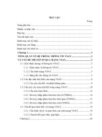
2.1 Nameplate data and naming rule
Nameplate data: for example CDI9200- G1R5T4:
Nameplate data
Type description
CDI 9200 G
1R5 T4
Delixi converter
Design number
Series number
G: General type P: Pump type
ZS: Injection Moulding type
GS: Isobaric water supply system
GY: Intelligent machine
Power of equipped electromotor (KW)
1R5 = 1.5KW
015 = 15KW
4
Voltage class
(rated voltage):
T2=220V
T4=380V
T6=660V
Chapter 2 Product Information
2.2 Technical Specifications
Control
Control mode
Control of space voltage vector
Frequency Resolution
Digital: 0.01Hz(below 100Hz), 0.1 Hz(above 100Hz)
Analog: 0.05Hz/50Hz, output frequency range: 0~400Hz
Frequency accuracy
Digital: 0.01% of the maximum output frequency
Analog: 0.1% of the maximum output frequency
Linear, square root, random V/F
1 minute for 150% of the rated current; 0.5 seconds for 200% of
the rated current(characteristics are inversely proportional to
time)
Manual torque compensation(0~30%), automatic torque
compensation
Keyboard/terminal/RS485 communication
V/F curve
Overload Capability
Torque ompensation
Operating mode
Frequency setting
Starting signal
Input
signal
Operation
Multiple stage speed
Acceleration and
deceleration time
Emergency stop
Inching motion
Automatic operation
Fault reset
Running state
Output
signal
Fault output
Analog output
Running function
Converter protection
Protective
function
Converter alarm
Instantaneous powerdown
Display
Key
Running informatin
board
Error informatin
Ambient temperature
Storage temperature
Environm
Ambient humidity
ent
Height/vibration
Application position
Cooling mode
Analog: 0 - 10V/0~5V,
2~10V/-10V~+10V,
4 - 20 mA /0-20 mA
Digital: keyboard/RS485 communication
Corotation, reversion
Up to eight speed is allowable (by using multiple function
terminal)
0-6000 second, acceleration and deceleration time is switchable
Acceleration and deceleration mode: linear, S-type
Interrupt output of converter.
Idle operation
Operate automatically according to parameter set (7 stage speed)
Reset fault state automatically if protective function is effective
Frequency inspection class, overload alarm, over voltage, under
voltage, overheat, running, stop, constant speed, automatic
program running
Contact output – AC 250V 1A, DC 30V 1A
Choose from output frequency, output current, and output
voltage VF1、VF2、︱VF1- VF2︱(output voltage: 0 - 10V,
0~20mA,4~20mA)
DC brake, frequency restriction, frequency jump, slip
compensation, protection against backward rotation, PID Control
and so on
Over current at constant speed, or during acceleration or
deceleration; over voltage at constant speed, or during
acceleration or deceleration; protection against module fault;
under voltage; overheat; overload; protection against exterior
faults; protection against EEPROM fault
Locked protection, overload alarm, temperature sensor fault.
Lower than 15 msec: Continuous operation
Bigger than 15 msec: Automatic restart is allowable
Set frequency, output current, output voltage, bus voltage, input
signal, feedback value, module temperature, output frequency,
synchronous speed of the motor and so on(Can be set up
P05.00-P05.24)
Running state of fault protection, four fault information are
saved.
-10 ℃ ~ 40 ℃
-20 ℃ ~ 65 ℃
90 % RH in max .(no dewing)
Below 1,000 m, below 5.9m/sec²(=0.6g)
No corrosive gas, inflammable gas, oil mist, dust and others
Air-blast cooling
5
Chapter 2 Product Information
2.3 CDI9200 Inverters
400V voltage level
Inverter type (G: load with
permanent torque P: fan
motor and pump load)
CDI9200-G0R75T4
CDI9200-G1R5T4
CDI9200-G2R2T4
CDI9200-G3R7T4/P5R5T4
CDI9200-P3R7T4
CDI9200-G5R5T4/P7R5T4
CDI9200-G7R5T4/P011T4
CDI9200-G011T4/P015T4
CDI9200-G015T4/P018.5T4
CDI9200-G018.5T4/P022T4
CDI9200-G022T4/P030T4
CDI9200-G030T4/P037T4
CDI9200-G037T4/P045T4
CDI9200-G045T4/P055T4
CDI9200-G055T4
CDI9200-P075T4
CDI9200-G075T4/P093T4
CDI9200-G093T4/P110T4
CDI9200-G110T4/P132T4
CDI9200-G132T4/P160T4
CDI9200-G160T4/P185T4
CDI9200-G185T4/P200T4
CDI9200-C200T4/P220T4
CDI9200-G220T4
CDI9200-P250T4
CDI9200-G250T4/P280T4
CDI9200-G280T4/P315T4
CDI9200-G315T4/P355T4
CDI9200-G355T4/P375T4
CDI9200-G375T4
CDI9200-P400T4
CDI9200-G400T4
CDI9200-P500T4
CDI9200-G500T4
Rated
capacity
(KVA)
1.5
3.0
4.0
5.9/8.5
5.9
8.5/11
11/17
17/21
21/24
24/30
30/40
40/50
50/60
60/72
72
100
100/116
116/138
138/167
167/200
200/224
224/250
250/276
276
316
316/355
355/395
395/467
447/467
467
494
494
612
612
Rated input
current
(A)
3.4
5.0
5.8
10.5/15.5
10.5
15.5/20.5
20.5/26
26/35
35/38.5
38.5/46.5
46.5/62
62/76
76/92
92/113
113
157
157/180
180/214
214/256
256/305
305/344
344/383
383/425
425
484
484/543
543/605
605/714
683/714
714
753
753
934
934
Rated output
current(A)
Matchable
Motor(kW)
2.3
3.7
5.0
8.8/13
8.8
13/17
17/25
25/32
32/37
37/45
45/60
60/75
75/90
90/110
110
152
152/176
176/210
210/253
253/300
300/340
340/380
380/420
420
480
480/540
540/600
600/680
680/710
710
750
750
930
930
0.75
1.5
2.2
3.7/5.5
3.7
5.5/7.5
7.5/11
11/15
15/18.5
18.5/22
22/30
30/37
37/45
45/55
55
75
75/93
93/110
110/132
132/160
160/185
182/200
300/220
220
250
250/280
280/315
315/355
355/375
375
400
400
500
500
Order explanation:
During order, please enter type, specification of the product, and provide parameter, load
type, or other information relating to the motor as much as possible. For any special
requirement, please consult with technology department of the Company.
6
Chapter 2 Product Information
2.4 Appearance and installation size
7
Chapter 2 Product Information
8
Chapter 2 Product Information
9
Chapter 2 Product Information
2.5 Routine maintenance
(1) Routine maintenance
Under influence of temperature, humidity, dust and vibration, internal elements of converter
should be aged, which should cause potential fault, or decrease service life of converter. Therefore, it
is significant to perform routine maintenance and regular inspection with the converter.
Routine maintenance item:
A
If running sound of motor is abnormal.
B
If vibration is created during operation of motor.
C
If installing condition of converter is changed.
D
If radiating fan of converter works normally.
E
If converter is in state of overheat.
Daily cleanness:
A
Keep cleanness of converter.
B
Remove dust from surface of converter effectively, to prevent converter from
incursion of dust, or metal dust.
C
Remove oil sludge form radiating fan of converter effectively.
(2)
Regular inspection
Please inspect corner pockets of converter regularly.
Regular inspection item:
A
Inspect air flue, and clean it regularly.
B
Inspect if screw is loosened.
C
Inspect if converter is corrosive.
D
Inspect if there is arc on surface connecting terminal.
E
Insulated test of major loop
Note: Please disconnect major loop and converter while testing insulation resistance by using
megohmmeter (500V DC megohmmeter). Do not measure insulation of control loop with
megohmmeter. And high voltage test is needless (finished in ex works).
(3)
Replacement of wearing parts
Wearing parts of converter includes cooling fan, filter ELCC, of which service life depend on
operating environment and maintenance condition closely.
User could confirm replacement period according to the operating time.
A
Cooling fan
Potential damage reason: Shaft abrasion and vane aging.
Critical standard: If there is crack on vane of fan, or if abnormal sound occurs during starting.
B
Filter ELCC
Potential damage reason: Bad input power, higher ambient temperature, frequent load switch, or
aging of electrolyte.
Critical standard: If liquid leaks, if safety valve bulged out, measure of static capacitance, and
measure of insulated resistance.
(4) Storage of converter
After purchased the device, please pay attention to following points while storing it:
A
Please store it in original package as much as possible.
B
Long term storage should cause aging of ELCC, please electrify it for 5 hours
above twice a year during storing, in mode of raising voltage to rated voltage slowly
via transformer.
10
Chapter 2 Product Information
(5)
Guarantee of converter
Maintenance free is limited to the converter only.
For fault or damage occurs during normal application of device sold in home (Bar code date):
A
And perform guaranteed repair in 18 months after delivery.
For exported device (not included China), the Company should provide guaranteed repair in six
months after delivery at purchase site.
For products manufactured by the Company, we will provide paid service for life anytime, or
anywhere applied it.
All sale, product, and agent units of the Company should provide products with after sale service,
of which service terms include:
A
Provide “Class Ⅲ” inspection service at site of the unit. (Include fault
elimination)
B
Refer to after sell service contract concluded between the Company and agents.
C
Request for compensated after-sell service from agent of the Company (without
reference to guaranteed repair).
Our Company should take responsibility of guaranteed repair, guaranteed exchange, and
guaranteed return for quality and accident responsibility relating to the product, but user could affect
insurance for further responsibility compensation guarantee from insurance agent.
Guarantee term of the product should be effective in 18 months after Bar code date.
For fault caused in following reason, user could obtain compensated maintenance only even
guarantee term is effective:
A
Problem caused in incorrect operation (based on user’s manual) or repair,
modification without authorization.
B
Problem caused in violation of critical requirement.
C
Damage caused in undeserved transportation after purchased.
D
Aging or fault caused in bad environment.
E
Damage caused in earthquake, fire, disaster, lightning strike, abnormal voltage
or other natural disaster and incidental disaster.
F
Damage occurs in transportation. (Note: transportation mode should be
appointed by user of themselves, the Company should assist agent to conduct transfer
of goods).
G
Brand, trade mark, SN, nameplate marked by manufacturer is damaged or
unjustifiable.
H
Failure to pay off fund according to purchase contract.
I
Failure to describe actual conditions relating to installation, distribution,
operation, maintenance, or other condition to the Company.
The Company should carry out responsibility of “Three guarantee” abovementioned only after
received the returned goods, and confirmed responsibility attribution.
Should it involve an unpaid or untimely settlement due to the buyer, the ownership hereof still
belongs to the supplier. In addition, the latter will assume no liability hereinabove, and the buyer shall
have no disagreement.
All relevant service fees shall be calculated in accordance with the identical standards of the
factory. In the event that an agreement or a contract exist, its priority shall be performed.
11
Chapter 3 Installation and Connection of Inverter
Chapter 3 Installation and cConnection of Inverter
3.1 Installation of front cover and number keyboard
3.1.1 Installation of front cover
1.Raise unit body by propping the seat; do not hold front cover and raise the
unit while moving it.
Otherwise main body maybe fall down and cause body injure.
2.Please install converter onto nonflammable materials (for example: Metal).
Violation of the rule maybe causes fire.
Warning
3.Please install a fan or other cooling device if installed device in a cabinet,
of which inlet temperature should be lower than 40℃.
Overheat maybe causes fire or damages the device.
This Section describes the necessary construction, setting condition, and space required by
installation of CDI9200 series converter.
It is needless to take down front cover and manipulater for general installation. Please
disassemble manipulater carefully because it connects with internal circuit via cables. Pull out cable
before assemble manipulater and panel, or plug should be damaged.
3.1.2 Installation of number keyboard
1. 0.37~7.5KW, take down and re-install digital operating keyboard as per the following
method:
A Take down digital operating keyboard:
Take down front lid and take out the digital operating keyboard from the clapboard.
B: Re-install the digital operating keyboard:
Press the digital operating keyboard into the clapboard keyboard framework and cover with the
front lid.
2. 11~500KW, take down and re-install digital operating keyboard as per the following
method:
A Take down digital operating keyboard:
Press lock clasp of number keyboard and take out it from front cover.
B Re-install the digital operating keyboard:
Press number keyboard into keyboard frame of panel, the lock clasp should lock number
keyboard automatically.
12
Chapter 3 Installation and Connection of Inverter
3.2 Selection of the Site and Space for Installation
Selection of installing position:
1. Prevent from sunniness; Don’t use in the open air directly.
2. Don’t use in the corrosive gas and liquid environment.
3. Don’t use in the oil fog and splash environment.
4. Don’t use in the salt spray environment.
5. Don’t use in the moist and rain environment.
Warning
6. Please equip the unit with filters device if metal dust or fiber wadding
existing in air.
7. Do not use the unit in mechanical shock or vibration condition.
8. It is necessary to adopt cooling measure if ambient temperature is higher than
40℃.
9. It is recommended to use the unit in temperature range of -10℃~+40℃
because fault maybe occur in overcool or overheat condition.
10. Keep the unit away from power supply noise, high-power application, such
as electric welder should impact application of the unit.
11. Emissive material should impact application of the unit.
12. Keep the unit away from combustible material, attenuant and solvent.
For ensuring perfect performance and long-term service life, please comply abovementioned
advices while installing CDI9200 series converter to prevent the unit from damage.
13
Chapter 3 Installation and Connection of Inverter
Selection of the installation space:
for vertical installation of CDI9200 series inverters, adequate cooling room should be left, so as
to ensure effective cooling
Installation space of CDI9200 inverters
1、The spaces to be left above/below and on the two sides of the inverter are
required both for the model with open bracket (IP00) and that with closed
bracket (IP20)
2、Permissible temperature at the air inlet: -10℃ ~ +40℃
3、Adequate cooling spaces should be reserved both above and below the
inverter, so as to facilitate gas admission and emission.
4、Do not drop anything into the air passage during installation. Otherwise
the fan might be damaged.
Attention
14
5、Mount filtering devices at the air inlet in cases of floating fiber or cotton
or heavy dust.
Chapter 3 Installation and Connection of Inverter
3.3 Wiring of the Peripherals and Optional parts
The following is a standard method to connect CDI9200 peripheral equipment and optional
components:
Note: Those labeled with “※” are optional parts
15
Chapter 3 Installation and Connection of Inverter
3.4 Wiring of the main circuit
3.4.1 Wiring diagram for the main circuit and precautions
This section describes connection of main circuit of CDI9200 inverters.
1. Do not make power supply of AC main loop connect with output terminal
U, V, and W.
2. Please connect unit only after shut down the power supply.
3. Verify if the crating voltage of converter is same as the input voltage of it.
Dangerous
4. Do not perform withstand test with converter.
5. Fasten terminal screw with appointed fasten torque.
Attention
1. Please check if grounding terminal is grounded before connect main loop.
(Refer to 3.6)
2. Terminal sequence should base on actual object.
3. Rated input voltage: 220V (AC single phase)/380V (three-phase), frequency:
50/60Hz
4. Allowable fluctuation voltage: +10%~-15% (fluctuation ±20%) Frequency:
±2%
Connection of main circuit of type 1:
Connection of main circuit of type 2:
Connection of main circuit of type 3:
16
Chapter 3 Installation and Connection of Inverter
Connection of main circuit of type 4-7:
Connection of main circuit of type 8-9:
17