Enhancement of void growth model for the anisotropic ductile metal (tt)
Bạn đang xem bản rút gọn của tài liệu. Xem và tải ngay bản đầy đủ của tài liệu tại đây (1008.14 KB, 28 trang )
ABSTRACT
The aim of work presented in this dissertation was to perform the improvement
of the existing void growth-based damage models used for the ductile fracture
analysis and prediction of sheet metals, which are subjected plastic
deformation. The original metal material is usually containing the second phase
particles or/and inclusions. Once the metallic material under deformation lead
to the nucleation, growth and coalescence of micro-voids that it is root of
ductile damage in industrial and civil products.
The first objective of this work was enhancement of N. L. Dung micro-void
growth model to predict ductile fracture behavior of sheet aluminum alloys,
typical for civil structures with anisotropic properties and their implementation
in user-defined material subroutine (VUMAT). The explicit finite element code
has been chosen for implementation of new material models. Constitutive
model with anisotropic yield criterion, damage growth and failure mechanism
has been developed and implemented into ABAQUS/Explicit software.
The second important aspect of this dissertation was performance of tensile
experiments in three different orientations of materials for identification of
mechanical behavior of high strength sheet aluminum alloys AA6061-T6. The
results from these tests allowed derivation of material constants for constitutive
models and help to a better understanding of anisotropic material behavior. The
tensile tests were also used to validate the accuracy and applied capability of
enhanced constitutive material models.
The constitutive models were developed within the general framework of
ductile damage mechanics. Coupling of the quadratic yield function Hill48 with
damage model based on micro-mechanical and continuum damage mechanics
(CDM) theories has been chosen to suit the anisotropic behavior of sheet
material. The validation of the constitutive models has been performed by
numerical simulations of tensile and Nakajima tests. The micro-crack and
1
fracture initiation, crack path, damage criteria and forming limit diagram (FLD)
of aluminum alloy AA6061-T6 are predicted using these constitutive models.
INTRODUCTION
1.1
The research motivation
The fracture phenomenon can be observed any everywhere in our daily lives.
The phenomenon of ductile fracture is usually happening in metallic forming
process under plastic deformation. Today, although high quality design and
manufacturing processes can result in robust, strong products, the causation of
fail cannot be avoided in some cases. However, this will not be an issue if
processes such as damage elimination or healing are included in the application.
Therefore, the prediction and characterization of micro-crack initiation, fracture
propagation and the final failure of the material is of such importance that it has
become a special field in materials science.
Recently, damage modeling and predicting of metal material and their alloys
are becoming more and more important as an object of research in recent years.
Until now, phenomenological continuum damage mechanics combined with
finite element method has mostly been used for numerical modeling of a
material damage. Two phenomenological approaches are usually used.
The first approach is based on theory of continuum damage mechanics (CDM).
In this method, damage variable is modeled by a scalar variable integrated with
a suitable yield function [1, 2]. One of the disadvantages of classical continuum
mechanics is the impossibility of predicting the micro-crack initiation.
The second approach is based on the micro-mechanical theory. This method
using a yield function containg a porousity (void volume fraction) that descibed
softening phenomenon of matrix material. Therefore, this theory-based damage
model is also known as porous ductile material model [3-5]. The primary
advantage of this approach is its micro-crack and fracture predictability via
porousity of matrix material.
2
Recently with the rapid development of advanced high strength steel and
aluminum alloy sheets, suitable material models are required for accurately
describing their anisotropic behavior. Therefore, improving the accuracy of
ductile fracture prediction for various metals by using various fracture predicted
models is still needed to continue.
1.2
The research objectives
An investigation of ductile fracture of sheet metallic material and their alloy
using N. L. Dung micro-void growth models [5, 6] was performed in this
dissertation. The following specific objectives had to be achieved in this work:
Understanding the mechanism of microscopic ductile fracture of metallic
materials and their alloys.
Improving the original damage models for predicting ductile fracture and shear
damage of anisotropic sheet metals.
Developing the user-defined material subroutine (VUMAT) for both porous
ductile material and continuum damage mechanics (CDM) theory-based
models.
Conducting the experiments to determine the mechanical behavior of material
and calibrate the material parameters for the constitutive models.
Applying the damage models to predict the ductile fracture of isotropic and
anisotropic metals.
1.3
Research methodology
An approach based on theoretical framework of ductile fracture together with
experimental observation is applied to this dissertation. The ductile damage
models of N. L. Dung [5, 6] are first enhanced to anisotropic sheet metal and
modified for shear damage by using the classical CDM and micromechanical
ductile damage theories. After this enhancement the damage models are written
in Fortran program language as the user material subroutines (VUMAT) for the
Abaqus/Explicit finite element package using the numerical algorithms [7, 8].
3
During this process the code is frequently verified from various aspects in such
a way that it works along with the existing capability of Abaqus/Explicit
software without any errors. Once the VUMAT subroutines are successfully
developed, the damage models would be verifed via predicting ductile fracture
of practical application (tensile test, deep drawing…).
1.4
The contributions of dissertation
An enhancement of N. L. Dung void growth model [5, 6] for anisotropic metal
using quadratic yield criterion Hill48 is proposed in this work. This approach
can be applied to the various yield criteria.
This work is also modified the N. L. Dung model [5, 6] for ductile fracture
prediction under pure and simple shear loading states.
The micro-crack and fracture criteria are formed by relationship between
equivalent plastic fracture strain and stress triaxiality. They help to reduce
computational time once they associated with CDM theory.
The forming limit diagram (FLD) of aluminum alloy sheet AA6061-T6 is
suggested in this dissertation.
The VUMAT subroutines can be used as the sourced codes for implementing a
new material model and developing current work in future.
1.5
Dissertation outline
The outline of this dissertation is as follows.
An introduction to ductile fracture mechanism of metallic material that occurs
due to the nucleation, growth and coalescence of voids is presented in chapter
2. A literature review of the existing porous ductile material models is also
shown in this chapter.
Chapter 3 details the enhancing ductile fracture criterion and porous ductile
material model (N. L. Dung models) for anisotropic material.
4
The numerically implemented procedure using the stress integrating algorithms
to seek element stress and state variables of damage models are represented in
chapter 4.
The experiments and an optimized tool are conducted to identify the input
material parameters of damage models would be outlined in chapter 5.
In chapter 6, the finite element calculations for tensile tests and deep drawing
process are performed. The numerical simulations of prediction of ductile
fracture in anisotropic metals are also compared to experimental results. A
ductile fracture criterion of the aluminum alloy is also proposed based on finite
element analysis.
Finally, in chapter 7 conclusions are made based on the results gained in
previous chapters and some discussions are presented for future work.
In addition, the appendixes and cited documents are also included in this
dissertation.
DUCTILE FRACTURE OF METALLIC MATERIAL
Ductile fracture of metallic material is due to heterogeneous microscopic
structures that decline the mechanical properties of the material. The metallic
material is usually containing the resource of microscopic damage such as
distributed micro-voids which might be process induced during loading are
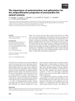
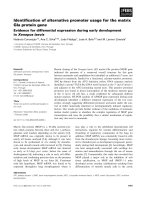
more tending to crack or failure. The Figure 2.1 shows the formation process of
ductile fracture due to micro-void nucleation, growth and coalescence in the
metal sheet under uniaxial tension [9].
In the recent time of several decades, the experimental studies and analytical
models of void nucleation, growth and coalescence have been conducted by
many researchers [3, 10-16].
The original void growth models are not feasible for ductile fracture prediction
under the range of low and negative stress triaxialities [17-19], i.e., they cannot
5
be used to predict ductile fracture in the cases of compressed and pure shearing
loads. To improve the predictive ability of the GTN-like model, Xue [18],
Nahshon and Hutchinson [19] have proposed the void coalescence models due
to the relatively shearing and rotational voids during plastic deformation. In this
work, the N. L. Dung porous ductile model [5] would be associated with
Nahshon and Hutchinson [19] shear damage criterion. In addition, a
modification of the N. L. Dung ductile fracture criterion [6] for shear damage
using CDM theory is also performed in this work.
Force (N)
Plastic strain evolution
Void nucleation, growth and coalescence
a)
Displacement (mm)
b)
Figure 2.1 Ductile fracture mechanism of metallic material: a) specimen, b) the
process of void nucleation, growth and coalescence versus plastic strain
evolution [9]
DUCTILE FRACTURE MODELLING
3.1
3.1.1
The continuum damage mechanics (CDM) model
The constitutive equations
The yield criterion in stress space is expressed in the following form:
( e , D ,
f
)=
e
6
− (1 − D
)
f
=0
(3.1)
where is softening exponent and e denotes equivalent stress,
For isotropic matrix material
e =e
3
=
M ises
2
(3.2)
s ij : s ij
For anisotropic matrix material, Hill48 equivalent stress is used as follow
e =e
H ill 4 8
1
=
2
ij : H ijkl : kl
(3.3)
The constant tensor H ijkl for Hill48 material is represented by 6x6 matrix as in
the material principal coordinate system
The damage variable D is considered as internal variable corresponding to a
material degradation
0 D 1,
D =0
where
corresponds to a virgin material
while D = 1 corresponds to fully damaged material.
1
D =
D crit
p
f
dD
=1
(3.4)
0
D crit is critical value of damage variable,
p
f
is equivalent plastic fracture
strain of matrix material, d D denotes the evolution rate of damage variable.
For the ellipsoidal void, N. L. Dung [5] proposed a critical accumulated damage
variable as follow (assuming 1 2 3 ),
dD
g
3 (1 − n ) + +
3 (1 − n ) −
3
1
2
3
2
3
=
sinh
cosh
1
−
n
4
4
(
)
f
f
3 1 − 2 − 3
p
+
d
4
f
Where i ( i = 1, 2, 3 ) denote the principal stress components.
d
p
(3.5)
the Hill48 equivalent plastic strain rate:
d
p
= d
p ( Hill 48 )
2 ( d ij : H ijkl : d ij )
−1
=
−1
Where H ijkl
is the pseudo-inverse matrix of Hill48 material.
7
(3.6)
3.1.2
An extension of the void growth model for shear damage
As a drawback of void growth-based damage model under simple or pure shear
load, the past studies indicated that there is no void growth under shear loading
states because of zero stress triaxiality but the voids are still rotated under this
condition. In an earlier study by McClintock [20] for void growth in shear
bands, the fracture due to void growth in the longitudinal direction of the shear
bands and the void shear is given by
ln
=
2
r
ln 1 +
+
2
dam age due to relatively shearing
and rotational void
2 (1 + n )
sinh
(1 − n ) m
(3.7)
f
dam age due to void grow th
McClintock [20] introduced a damage criterion including both void growth anf
relatively shearing and rotational as Eq.(3.7).
This work modifed the N. L. Dung damage accumulate criterion and proposed a
shear damage variable as follow,
ln 1 + 2 N (
D =
s
1
ln 0 − g
2
r
D
crit
0
Ratio of
0
p
)
2
(3.8)
p
f
dD
g
0
/ 2r0 calculated through initial VVF.
The damage criterion for general loading case is written
D = D + g ( ) D
g
s
(3.9)
Where g ( ) is Lode weighted function. Complete damage occurs once damage
variable reaches to unity. i.e.,
3.2
D =1
The porous ductile model
In order to consider anisotropic aspect of sheet material, the original Dung
model [5] will be associated with ewuivalent stress Hill48 as follow,
D ung − H ill 48
H ill 48
= e
f
2
+ 2 fq1 cosh
3 (1 − n ) m
− 1 − q2 f
f
2
=0
(3.10)
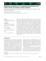
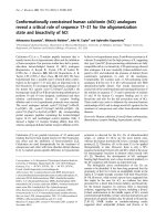
The clossed yield surface of the Dung-Hill48 model is shown in Figure 3.1
8
Figure 3.1 The yield surface presentation of the Dung-Hill48 model in
normalized principal stress space.
NUMERICAL IMPLEMENTATION OF THE DUCTILE
DAMAGE MODELS
This chapter describes the implementation of the constitutive models in chapter
3 into FEM code of ABAQUS/Explicit software via the VUMAT subroutines.
For this dissertation, the VUMAT subroutines are written by program language
Fortran 90 and integrated with FEM code of ABAQUS/Explicit software
package version 6.14-3.
4.1
Numerical implementation of CDM model
The Hill48 yield criterion would be implemented by using “cutting-plane”
algorithm [7]. The flowchart of stress integration algorithm of CDM model is
given in appendix 1.
4.2
Numerical implementation of the porous ductile model
A numerical algorithm for pressure-dependent plasticity models [8] is applied
to this dissertation.
9
The flowchart of stress integration algorithm of porous ductile model is shown
in appendix 2.
4.3
Verification of user-defined material subroutine (VUMAT)
To verify the accuracy of the implementation against known values and element
distortion, the VUMAT subroutines would be verified via single element,
tensile specimen and deep drawing process.
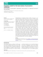
Results of tensile test: Figure 4.1 shows an identical crack path obtaining by
experiment and numerical simulation of uniaxial tensile specimen. Figure 4.2
shows a comparison of force-displacement curve between the experiment and
numerical simulations. The numerical results show a good agreement with
experimental data when using the CDM-Hill48 model with fitted parameter set,
whereas a larger displacement amount is archived by Dung-Hill48 model
comparing with that of experiment. This may be due to effect of hardening
exponent in Dung-Hill48 model during plastic deformation process.
a)
b)
c)
Figure 4.1 Comparison of the crack path. (a) experiment [21], (b) CDM-Hill48
model, (c) Dung-Hill48 model
10
Figure 4.2 Force – displacement curves of tensile test
(a)
(b)
(c)
Figure 4.3 Comparison of fracture path between experiment and numerical
simulations. (a) experiment, (b) CDM-Hill48 model, (c) Dung-Hill48 model
The result of deep drawing test: The predicted fracture path by numerical
simulation having identical shape and location with experiment is shown Figure
4.3. The forming force versus punch stroke curve is presented by Figure 4.4.
The predicted curves underestimate the experimental data and punch depth at
moment of fracture occurrence of 16.1 mm, 19.3 mm and 18.7 mm are archived
by CDM-Hill48, Dung-Hill48 model and experiment, respectively.
11
Figure 4.4 Comparison of forming force curve between experiment and
numerical simulations
IDENTIFICATION OF MATERIAL PARAMETERS
5.1
Experimental work
The aluminum alloy sheet AA6061-T6 that its thickness of T = 2 mm is used to
investigate ductile fracture in this work.
The all specimens are designed based on ASTM-E8 [22] standard. The
chemical composition of AA6061-T6 alloy was tested by a method of ASTM
E1251-11 standard [23] is given in Table 5.1.
Table 5.1 Chemical composition of AA6061-T6 aluminum alloy
Element
Si
Fe
Cu
Mn
Mg
Cr
Zn
Ti
Al
Content
(%)
0.55
0.36
0.298
0.069
0.93
0.192
< 0.001
0.014
balance
The tensile tests are performed on a universal testing machine (Testometric
M500-30AT) with loading capacity of 30 ton.
The isotropic hardening model is assumed to obey Swift [24] law. The
unknowns (K, ε0, n) that should be determined by the equation (5.1) following
the least square root method.
Where
K
f
= K ( 0 +
p
)
n
(5.1)
and 0 are material constants, n hardening exponent. The optimum
curve is shown in Figure 5.1.
12
Figure 5.1 The best fit hardening curve
The value of anisotropic coefficients is given as Table 5.2. The best fit
parameters are given in Table 5.3.
Table 5.2 The anisotropic coefficients of Hill48 equivalent stress function.
F
G
H
M
L
N
0.67
0.65
0.35
1.35
1.5
1.5
Table 5.3 The hardening model parameters of the anisotropic material
5.2
5.2.1
Parameters
K (MPa)
0
n
Value
489.74
0.02
0.179
Calibration of the material parameters for the damage models
The calibrated approach
The Genetic Algorithm (GA) global optimization approach, which is a built-in
optimization function in MATLAB, is employed to optimize the necessary
parameters. Parameters of the model are obtained from an inverse engineering
analysis which aims at minimizing the discrepancy of force-displacement
curves provided by simulation and tensile test of a dog-bone specimen.
5.2.2
CDM model.
Assuming that initial VVF of f 0 = 0.0016 . The constant of = 1 in weight
function is selected.
13
The critical damage parameter of due to void growth
(D )
g
crit
and softening
exponent ( ) would be calibrated.
Table 5.4 Initial guess values and constrains for optimization process
Parameter
D crit
β
Upper limit
3.0
3.0
Initial guess
2.0
2.0
Lower limit
0.1
1.0
g
g
The Table 5.4 shows boundary condition and initial values of D crit
and . The
best-fit material parameters that archived from optimization process are given
in Table 5.5 and the optimal force-displacement curves are shown in Figure 5.2.
Table 5.5 The best-fit material parameters for CDM model
Parameter
D crit
β
CDM-Mises
2.65
1.25
CDM-Hill48
1.32
1.96
g
Figure 5.2 The best-fit force-displacement curve using CDM model
5.2.3
Porous ductile model
The Table 5.6 shows boundary condition and initial values of input pparameters
for the porous ductile model. The best-fit material parameters that archived
14
after optimization process are given in Table 5.7 and the optimum forcedisplacement curves are shown in Figure 5.3.
Table 5.6 Initial guess values and constrains for optimization process
q1
q2
fF
fC
f0
εN
sN
fN
Upper limit
2.0
4.0
0.25
0.1
0.0020
0.65
0.15
0.07
Initial guess
1.5
2.25
0.15
0.06
0.0018
0.3
0.1
0.05
Lower limit
1.0
1.5
0.101
0.02
0.0014
0.085
0.05
0.03
Table 5.7. The optimal values for Dung-Hill48 model
Parameter
q1
q2
fF
fC
f0
N
sN
fN
Value
1.321
2.582
0.14
0.087
0.0016
0.115
0.054
0.0515
Figure 5.3 The best-fit force – displacement curve using of Dung-Hill48 model
DUCTILE FRACTURE PREDICTION OF AA6061-T6
ALUMINUM ALLOY
6.1
6.1.1
The tensile tests
Geometries, mesh and boundary conditions
The R-notched specimens are cut from thin sheet that its nominal thickness of 2
mm.
All experimental data is obtained using tensile testing machine
Testometric M500-30AT. The initial mesh size at analysis zone is 0.5 mm x 0.5
mm. The eight-node brick element type with reduced integration and hourglass
15
control (C3D8R) has been used. The left-hand side of specimen is fixed
wheareas the tensile load is applied on the right-hand side of the specimen.
6.1.2
Ductility prediction
The predicted values of ductility and corresponding errors are presented in
Table 6.1. The relative error is calculated by eq. (6.1) as below,
D uctility ( exp .) − D uctility ( sim .)
Error ( % ) =
100
(6.1)
D uctility ( exp .)
Where the subscripts • ( ex p .) and • ( sim .) imply the experimental and predicted
ductility, respectively.
Table 6.1 The ductility predictions of the R-notched specimen
Ductility (%)
Specimen
Error (%)
Experiment
CDMHill48
DungHill48
CDMHill48
DungHill48
Dog-bone
R6
14.77
2.67
14.66
2.80
14.63
2.65
0.74
4.87
0.97
0.79
R3
2.18
2.24
2.22
2.75
1.54
R1.5
Average
1.99
1.66
1.98
16.88
6.31
0.70
1.00
The maximum error values of predicted ductility by CDM-Hill48 model is
16.88 % and by Dung-Hill48 model is 1.54 %. The average error values of 6.31
% and of 1.00 % are obtained by CDM-Hill48 model and Dung-Hill48 model,
respectively. The detail results are given in Table 6.1. Crack initiation and
propagation prediction.
The micro-crack initiation locations are determined by extracting VVF along
minimum section of the specimens and are given in Figure 6.1. It predicted that
in the case of dog-bone and R6 notched specimens micro-crack initiated at
center, whereas in the case of R3, R1.5 and shear specimens micro-crack
initiates near periphery.
16
Figure 6.1 Micro-crack location of R-notched specimens
The predicted fracture initiation locations using CDM-Hill48 model are
identical to those of Dung-Hill48 model. For all R-notched and shear
specimens, the fracture propagates along minimum section. The fracture
initiates at center of the dog-bone and R6 specimens, whereas fracture initiates
at periphery of R1.5 and shear specimens. For the R3 specimen, there is small
deference between predicted result by CDM-Hill48 model and Dung-Hill48
model. Fracture occurs at periphery before when predicted by CDM-Hill48
while that the fracture initiates at very close to periphery when using DungHill48 model. The summary of predicted result of fracture initiation locations is
given in Table 6.2.
Table 6.2 Summary of fracture initiation location prediction
Specimen
Dog-bone
R6
R3
R1.5
Shear
CDM-Hill48
Center
Center
Periphery
Periphery
Dung-Hill48
Center
Center
Periphery
Near
periphery
Periphery
Periphery
6.1.3
Ductile fracture strain prediction
The predicted micro-crack and fracture strains that using as the ductile fracture
criteria of the AA6061-T6 aluminum alloy sheet are described in Figure 6.2.
17
Figure 6.2 Equivalent plastic fracture strain as a function of average stress
triaxiality
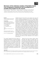
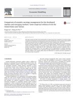
6.2
Forming limit diagram (FLD) prediction
Forming limit points identified from earliest failure elements in each specimen
using the combined Dung-Hill48 model are plotted in Figure 6.3. The same
procedure is applied to simulation results with the GTN model using the same
parameter set to determine limiting strains (contour plots of this case are not
shown). Based on these points forming limit diagrams of the material are
obtained for the two models. The two curves are just a small distance apart
resulting from a mild anisotropy of the material. In particular, the GTN
isotropic material model underestimates the forming limits in most cases except
for in proximity of the equi-biaxial stretching mode.
Equivalent plastic strains at the forming limits are computed and plotted against
corresponding average triaxiality values in Figure 6.4. Representation of these
states are located at the zone between micro-crack and macro-crack loci. Hence,
the micro-crack condition ( f = f C ) can be applied as a conservative measure
of the formability of the material. Also, the micro-crack condition ( f = f F )
serves as an upper bound.
18
Figure 6.3 The forming limit diagram of AA6061-T6 aluminum alloy
Figure 6.4 The equivalent plastic fracture strain of AA6061-T6 aluminum alloy
CONCLUSIONS AND FUTURE WORK
7.1
The overall conclusions
This research has focused on improving and applying the ductile damage
models that can predict the plastic failures of the anisotropic metallic sheet.
This has required a combination of high quality experimental data obtaining by
19
tensile tests and the material parameter calibration of the damage models. The
principal conclusions have been summarized in detail below:
The original ductile damage models were enhanced for anisotropic matrix
material. The applicability of both continuum damage mechanics theory-based
model (CDM-Hill48 model) and porous ductile theory-based model (DungHill48 model) were examined.
The user-defined material subroutines (VUMAT) in ABAQUS/Explicit were
successfully developed for the numerical computation. These VUMAT
subroutines can be usefully sourced code for implementation of various
material models in the future.
The series of experiment are also conducted for identifying the input material
parameters and validating the proposed damage models.
The FEM simulations were performed on uniaxial tension, deep drawing and
Nakajima tests. The numerical results show that the response of forcedisplacement curve obtaining by Hill48 matrix material-based damage models
is more suited to experimental data than those of the von Mises matrix material
assumption. This reflects the correctness of the enhanced models comparing
with original damage models.
Using critical values of the void volume fraction, the predictions of micro- and
fracture initiation of the material are performed to obtain the equivalent plastic
strains at fracture. In that sense, the porous plasticity model is employed to
establish a ductile fracture criterion of the material via the construction of a
plastic strain – triaxiality relation. Such relation can later be used as an
alternative fracture criterion based on CDM theory.
The FLD of AA6061-T6 sheet is predicted using the Dung-Hill48 model. The
predicted result sits above the one obtained with GTN model for most
deformation mode except for the neighborhood of the equi-biaxial stretching
state, the different apart reflects anisotropic assumption of matrix material in
20
Dung-Hill48 model. The prediction of forming limits are consistent with the
established fracture plastic strain - triaxiality relation that obtained by tension
and Nakajima test when using both damage models (CDM-Hill48 and DungHill48).
7.2
The recommends for future work
In this work, to save computational time, a consistent mesh size is used for
calibrating and validating the ductile fracture analyses. However, in finite
element method, the mesh dependence is well known problem for damage
analyses due to softening behavior of matrix material. Therefore, it would be
adequate evaluation if a particular mesh size which gives accurate results is
investigated.
The aluminum alloys are known as the crystalline structure material so that a
further damage investigation based on grain structure analyses at microscopic
level is important.
This work marks the first attempt to incorporate sheet metal anisotropy into a
porous plasticity model to predict ductile fracture and forming limits of the
aluminum alloy. As such, a simplest extension of the J2 flow theory, the Hill’s
quadratic plasticity model, is chosen. Nevertheless, it is rather well-known that
the aluminum alloy considered obeys non-quadratic yield function. Therefore,
the present approach should be applied to more sophisticated yield functions.
The effect of strain rate and temperature in warm and hot forming process
should be studied.
The tests should be carried out on specimens under lager range of stress
triaxialities to archive full locus of fracture strain for AA6061-T6 aluminum
alloy.
21
Appendix 1: Flow chart of stress integrated algorithm of CDM-Hill48 model
22
Appendix 2: Flow chart of stress integrated algorithm of Dung-Hill48 model
23
References
[1]
J. Lemaitre, "A continuous damage mechanics model for ductile
fracture," Journal of engineering materials and technology, vol. 107,
no. 1, pp. 83-89, 1985.
[2]
L. Xue, "Damage accumulation and fracture initiation in uncracked
ductile solids subject to triaxial loading," International Journal of
Solids and Structures, vol. 44, no. 16, pp. 5163-5181, 8/1/ 2007.
[3]
A. L. Gurson, "Continuum Theory of Ductile Rupture by Void
Nucleation and Growth: Part I—Yield Criteria and Flow Rules for
Porous Ductile Media," Journal of Engineering Materials and
Technology, vol. 99, no. 1, pp. 2-15, 1977.
[4]
M. Gologanu, J.-B. Leblond, and J. Devaux, "Approximate models for
ductile metals containing non-spherical voids—Case of axisymmetric
prolate ellipsoidal cavities," Journal of the Mechanics and Physics of
Solids, vol. 41, no. 11, pp. 1723-1754, 11// 1993.
[5]
N. L. Dung, "Three Dimensional Void Growth in Plastic Materials,"
Mechanics Research Comunications, vol. 19, no. 3, p. 227, 1992.
[6]
N. L. Dung, "Plasticity theory of ductile fracture by void growth and
coalescence," Forschung im Ingenieurwesen, vol. 58, no. 5, pp. 135140, 1992.
[7]
M. Ortiz and J. Simo, "An analysis of a new class of integration
algorithms for elastoplastic constitutive relations," International
Journal for Numerical Methods in Engineering, vol. 23, no. 3, pp. 353366, 1986.
[8]
N. Aravas, "On the numerical integration of a class of pressuredependent plasticity models," International Journal for Numerical
Methods in Engineering, vol. 24, no. 7, pp. 1395-1416, 1987.
24
[9]
F. Abbassi, T. Belhadj, S. Mistou, and A. Zghal, "Parameter
identification of a mechanical ductile damage using Artificial Neural
Networks in sheet metal forming," Materials & Design, vol. 45, pp.
605-615, 2013.
[10]
N. Dung, "Plasticity theory of ductile fracture by void growth and
coalescence," (in English), Forschung im Ingenieurwesen, vol. 58, no.
5, pp. 135-140, 1992/05/01 1992.
[11]
A. Needleman and V. Tvergaard, "An analysis of ductile rupture modes
at a crack tip," Journal of the Mechanics and Physics of Solids, vol. 35,
no. 2, pp. 151-183, // 1987.
[12]
A. Weck, D. Wilkinson, and E. Maire, "Observation of void nucleation,
growth and coalescence in a model metal matrix composite using X-ray
tomography," Materials Science and Engineering: A, vol. 488, no. 1,
pp. 435-445, 2008.
[13]
N. Kanetake, M. Nomura, and T. Choh, "Continuous observation of
microstructural degradation during tensile loading of particle reinforced
aluminium matrix composites," Materials Science and Technology, vol.
11, no. 12, pp. 1246-1252, 1995.
[14]
F. A. McClintock, "A Criterion for Ductile Fracture by the Growth of
Holes," Journal of Applied Mechanics, vol. 35, no. 2, pp. 363-371,
1968.
[15]
J. R. Rice and D. M. Tracey, "On the ductile enlargement of voids in
triaxial stress fields," Journal of the Mechanics and Physics of Solids,
vol. 17, no. 3, pp. 201-217, 6// 1969.
[16]
V. Tvergaard and A. Needleman, "Analysis of the cup-cone fracture in
a round tensile bar," Acta Metallurgica, vol. 32, no. 1, pp. 157-169, 1//
1984.
25