Xe ô tô hyundai excel toàn tập hyundai excel - P17
Bạn đang xem bản rút gọn của tài liệu. Xem và tải ngay bản đầy đủ của tài liệu tại đây (261.35 KB, 18 trang )
LUBRICATION
AND
MAINTENANCE
Return To Main Table of Contents
SCHEDULED MAINTENANCE TABLE
...................
2
RECOMMENDED LUBRICANTS AND CAPACITES
........... 4
MAINTENANCE SERVICE
.............................
5
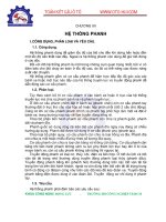
SCHEDULED MAINTENANCE TABLE
SCHEDULED MAINTENANCE TABLE
RECOMMENDED CUSTOMER MAINTENANCE
The following maintenance services must be performed to assure good emission control and performance. Keep
receipts for all vehicle emission services to protect your emission warranty.
When both mileage and time are shown, the frequency of service is determined by whichever occurs first.
R : REPLACE
I : INSPECT, AFTER INSPECTION, CLEAN
ADJUST, REPAIR OR REPLACE IF NECESSARY
SCHEDULED MAINTENANCE
MILES
x 1000
7.5
15
22.5
30 37.5
45 52.5 60
NO
DESCRIPTION
KILOMETERS
x 1000
12
24 36 48
60 72 84 96
MONTHS
6
12
18
24
30 36 42 48
GENERAL MAINTENANCE
1 COOLING SYSTEM (HOSES, CONNECTIONS, ETC)
I
I
I
I
2 ENGINE COOLANT
R R
3
TIMING BELT
R
4 MANUAL T/M OIL
R R
5
AUTO T/M OIL
6 BRAKES HOSES, LINES
R
I
R
R
I
R
7
BRAKE FLUID
I
I
I
I
8
REAR BRAKE DRUMS/LININGS
I
I I I
9
BRAKE PADS, CALIPERS, ROTORS
I
I
I I
I
I I
I
10
PARKING BRAKE
I
I
I
I
11
EXHAUST PIPE CONNECTIONS, MUFFLER AND
I
I
I I
SUSPENSION BOLTS
12
STEERING GEAR BOX, LINKAGE AND BOLTS
I
I I
I
13
REAR WHEEL BEARING GREASE
I
I
14 DRIVESHAFTS AND BOOTS
I
I
I
15
POWER STEERING FLUID PUMP BELT
I
I
I
I
16
POWER STEERING FLUID
I
I
I
I
17
POWER STEERING HOSES
I
I I I
10-2
SCHEDULED MAINTENANCE TABLE
SCHEDULED MAINTENANCE UNDER SEVERE USAGE CONDITIONS
The following items must be serviced more frequently on cars normally used under severe driving conditions. Refer to
the chart below for the appropriate maintenance intervals.
SEVERE DRIVING CONDITIONS
A - Repeated short distance driving
B - Extensive in dusty conditions
C - Driving in dusty conditions
D - Driving in areas using salt or other corrosive materials or in very cold weather
E - Driving in sandy areas
F - More than 50% driving in heavy city traffic during hot weather above 32°C (90°F)
I = Inspect, correct or replace if necessary
R = Replace.
Maintenance item
Engine Oil
Maintenance
operation
R
Maintenance interval
Every 3,000 Miles
(4,800 Km)
or 3 Months
Driving
condition
A, B, C, F
Engine Oil Filter
R
Every 3,000 Miles
(4,800 Km)
or 3 Months
A, B, C, F
Air Cleaner Filter
Crankcase Emission
Control System
(PCV Valve)
Spark Plugs
R
I
R
More Frequently
More Frequently
Every 24,000 Miles
(40,000 Km)
or 18 Months
C, E
C,
B,
Brake Pads,
Calipers, Rotors
Rear Brake
Drums/Linings
Steering Gear Box
Linkage and Boots
I
I
I
More Frequently
More Frequently
Every 7,500 Miles
(12,000 Km)
or 6 Months
C, D
C, D
C, D, E, F
Driveshaft and
Boots
I
Every 7,500 Miles
(12,000 Km)
or 6 Months
C, E, F
10-3
RECOMMENDED LUBRICANTS AND CAPACITIES
RECOMMENDED LUBRICANTS AND CAPACITIES
RECOMMENDED LUBRICANTS
Parts
Engine oil
Manual transmission
Automatic transmission
Brake
Rear wheel bearing
Cooling system
Transmission linkage, parking
brake cable mechanism, hood
lock and hook, door latch,
seat adjuster, tailgate latch,
door hinges, tailgate hinges
Door hinges, tailgate hinges
Power steering
LUBRICANTS CAPACITIES
Specifications
API classification SF or
SF/CC
API classification GL-4
Automatic transmission fluid
“DEXRON
®
OR DEXRON
®
II” type
Conforming to DOT 3 or equivalent
Multi-purpose grease NLGI
Grade #2, EP
High quality ethylene glycol
Multi-purpose grease NLGI
Grade #2
Engine oil
DEXRON
®
II type
Remarks
For further details, refer to
SAE viscosity number
SAE grade number:
SAE 75W-85W
Concentration level 50%
Description
Engine oil
Oil pan
Oil filter
Total
Cooling system
Manual transaxle
Automatic transaxle
Power steering
Capacities
3.0 lit. (3.2 U.S.qts, 2.7 Imp.qts.)
0.5 lit. (0.53 U.S.qt., 0.44 Imp.qt.)
3.5 lit. (3.5 U.S.qts, 3.1 Imp.qts.)
5.0 lit. (5.3 U.S.qts, 4.4 Imp.qts.)
2.1 lit. (2.2 U.S.qts, 1.8 Imp.qts.)
5.8 lit. (6.1 U.S.qts, 5.1 Imp.qts.)
0.8 lit. (49 C.I.D)
Remarks
10-4
MAINTENANCE SERVICE
MAINTENANCE SERVICE
ENGINE OIL
Always use lubricants which conform to the requirements of
the API classification “For Service SF” or For Service SF/CC”
when available, and have the proper SAE grade number for the
expected temperature range.
NOTE
(a) If necessary, warm up the engine.
(b) Remove the oil filter cap to allow the oil to drain easily.
Oil capacity: 3.0 (3.2, 2.7)
Oil pan: 0.5 (0.53, 0.44)
Oil filter: 3.5 (3.7, 3.1)
ENGINE OIL FILTER
1. Remove the oil filter with a suitable wrench.
2. For installation, apply engine oil to the oil filter gasket and
tighten the oil filter fully by hand.
CAUTION
Be sure gasket sealing surface on engine block is clean and
free of debris.
Be sure to remove old gasket from block prior to installing
new filter.
DRIVE BELT
1. To check belt tension, apply moderate pressure (approximately
100 N, 22 lb) midway between the pulleys.
Check the deflection and adjust if necessary.
Drive belt deflection . . . . . . . . . . . . . . 7-9 mm (0.28-0.35 in.)
VALVE CLEARANCE
Intake and Exhaust Valves
Adjustment condition:
Normal operating temperature [Coolant temperature 80 to
90°C (176 to 194°F)]
1. Place piston of No. 1 cylinder at top dead center of compression
stroke to adjust valve clearances marked A, as shown, in the
next page.
2. Loosen nut and adjust to specification with adjusting screw.
Then retighten nut.
Valve clearance (on hot engine)
Intake
. . . . . . . . . . . . . . . . . . . . . . . . . . . . . .
0.15 mm (0.006 in.)
Exhaust
. . . . . . . . . . . . . . . . . . . . . . . . . . . .
0.25 mm (0.010 in.)
MAINTENANCE SERVICE
3. After nut has been retightened, recheck to see if clearance is
correct.
4. Place piston in No. 4 cylinder at top dead center on compres-
sion stroke to adjust valve clearance marked B, as shown.
5. Adjust by repeating steps 2 and 3.
6. Check idle speed and readjust if necessary.
Jet Valve
Adjustment condition:
Normal operating temperature [Coolant temperature 80 to
90°C (176 to 194°F)]
CAUTION
(a) An incorrect jet valve clearance will affect the emission
levels and could also cause engine troubles.
(b) Adjust the jet valve clearance before adjusting the
intake valve clearance. The cylinder head bolts should be
retightened before attempting this adjustment.
(c) The jet valve clearance should be adjusted with the
intake valve adjusting screw fully loosened.
1.
Place piston of No. 1 cylinder at top dead center of compression
stroke to adjust valve clearances marked A of intake valve side.
2. Back off the intake valve adjusting screw (two or more turns).
3. Loosen the lock nut on the jet valve adjusting screw.
4. Back off the jet valve adjusting screw and place a 0.25 mm
(0.010 in.) leaf of the feeler gauge between the top end of the
jet valve stem and the bottom end of the adjusting screw.
Jet valve clearance (on hot engine). . . . . 0.25 mm (0.010 in.)
5. Screw in the adjusting screw (clockwise) until the bottom end
of the adjusting screw touches the feeler gauge. Since the jet
valve spring is weak in tensile strength, use special care not to
force the jet valve in. Be careful particularly if the adjusting
screw is hard to turn.
6.
While holding the adjusting screw in place with a screwdriver,
tighten the lock nut firmly.
7.
Check with leaf of the feeler gauge to ensure a 0.25 mm (0.010
in.) clearance.
8. Adjust the intake valve clearance.
9. Place piston in No. 4 cylinder at top dead center on compres-
sion stroke to adjust valve clearances marked B of intake valve
side.
10. Adjust by repeating steps 2 and 8.
10-6
MAINTENANCE SERVICE
IGNITION TIMING (Check and adjust as required)
Adjustment condition:
Lights, electric cooling fan and all accessories are off, and
transmission is in neutral.
1.
Run the cold engine at fast idle until the cooling water tempera-
ture is raised to 80 to 95°C (176-203°F)
2. Run the engine at the specified curb idle speed.
3. Read the ignition timing. (Refer to the next page).
If outside specified limits, adjust the ignition timing by rotating
the distributor after loosening the distributor fitting nut.
Basic Ignition Timing Set Procedure at High-altitude
Adjustment condition:
Lights, electric cooling fan and all accessories are off, and
transmission is in neutral.
1.
Run the cold engine at fast idle until the cooling water tempera-
ture is raised to 80-95°C (176-203°F)
2. Disconnect the hoses from the distributor and temporarily seal
the hoses end (Vacuum OFF).
3. Run the engine at the specified idle speed (rpm).
4. Read the ignition timing.
If outside specified limits, adjust the ignition timing by rotating
the distributor after loosening the distributor fitting nut.
5. Reconnect the vacuum hoses to the distributor.
ENGINE IDLE SPEED CHECK PROCEDURE
By the idle speed check procedure, check if the engine is idling
at the specified speed. If not, adjust the idle speed to the speci-
fied value by the adjusting procedure.
CAUTION
The improper setting (throttle valve opening) will increase
exhaust gas temperature at deceleration, reducing catalyst
life greatly and deteriorating exhaust gas cleaning perform-
ance.
Engine Idle Speed Adjustment
Adjustment condition:
Lights and all accessories are off, transmission is in neutral and
parking brake pulled.
1.
Run the cold engine at fast idle the coolant temperature is 80 to
95°C (176-203°F).
2.
Run the engine for more than 5 seconds at an engine speed of
2,000 to 3,000 rpm.
3. Run the engine at idle for 2 minutes.
4. Using a tachometer, check the idling speed. If it does not meet
specifications, readjust the speed to the normal specification
using the idle speed adjusting screw SAS 1.
10-7