NGHIÊN cứu và đề XUẤT GIẢI PHÁP bảo vệ CHỐNG sét CHO CÔNG TRÌNH điển HÌNH ở VIỆT NAM tt tiếng anh
Bạn đang xem bản rút gọn của tài liệu. Xem và tải ngay bản đầy đủ của tài liệu tại đây (1.53 MB, 44 trang )
MINISTRY OF EDUCATION AND TRAINING
HO CHI MINH CITY UNIVERSITY OF TECHNOLOGY AND EDUCATION
LE QUANG TRUNG
STUDY AND PROPOSE SOLUTIONS FOR
LIGHTNING PROTECTING FOR TYPICAL SITE IN VIET NAM
SUMMARY OF THE THESIS
ELECTRICAL ENGINEERING
Code: 62520202
Ho Chi Minh city, 6/2019
MINISTRY OF EDUCATION AND TRAINING
HO CHI MINH CITY UNIVERSITY OF TECHNOLOGY AND EDUCATION
LE QUANG TRUNG
STUDY AND PROPOSE SOLUTIONS FOR
LIGHTNING PROTECTING FOR TYPICAL SITE IN VIET NAM
SUMMARY OF THE THESIS
ELECTRICAL ENGINEERING - 62520202
Scientific guide:
1. Assoc. Prof. Quyen Huy Anh
2. Assoc. Prof. Vu Phan Tu
Ho Chi Minh city, 6/2019
CHAPTER 1
INTRODUCTION TO THE STUDY
1.1.
Reason to choose the topic
Vietnam located in a humid tropical region with monsoon climate and high lightning
strike density. Therefore, the damage caused by lightning to people, services and the annual
economy is enormous.
In particular, now science and technology is increasingly developing, IOT (Internet
Of Thing) is applied in many fields; devices used in the field of electricity, electronics and
especially in the field of telecommunications, computer networks, ... are sensitive to high
voltage so easily damaged when there is a sudden change of electricity and voltage due to
lightning. Especially, nowadays, science and technology is increasingly developing, IOT
(Internet Of Thing) is applied in many fields; the devices are used in field such as
electricity, electronics, computer networks, and especially in telecommunications, etc.
which are sensitive to high voltage thus they are easy to be damaged when there is a sudden
change of current and voltage due to lightning.
Damage caused by lightning to electrical and electronic equipment often occurs in
the two following cases:
- Damage caused by direct lightning strikes: Lightning strike on a structure can cause
damage to property, electronic and electrical systems inside the structure and especially
people.
- Damage caused by surge on the power line: When lightning strike near the structure
or when lightning strikes directly or near power lines or service lines (main electrical
wiring systems, communication lines, ...) connected to the structure, the equipment inside
the structure may be damaged due to overvoltage. In this case, damage caused by lightning
is not just to replace the equipment but more serious damage is to stop the service or lose
data. Specifically in Vietnam, according to statistics in 2001, for the electricity industry,
there are 400 incidents that 50% caused by lightning (Tien Phong Newspaper 14/08/02).
As for Posts and Telecommunications, there are 53 lightning incidents (27.13% of
telecommunications incidents) causing 4,119 billion damage and the total time of
disconnect due to lightning is 716 hours (Lightning protection for Vietnam
telecommunication network - Shortcomings. Le Quoc Tuan - Telecommunications
Department, Pham Hong Mai - TTTTBD).
Since 1998, together with the study of lightning protection technology and the
proposed to lightning protection solutions, many organizations have implemented, as
well as the establishment of companies in this field has created conditions for us to access
to modern lightning protection technologies and equipment, but most of the lightning
protection solutions offered in Vietnam are not general including from the assessment of
the risk of damage caused by lightning to determine the required lightning protection level.
From that basis, the proposal of protection solution (or protection level) of appropriate
lightning protection.
Currently, there are many projects in the world [7 ÷ 16, 18 ÷ 20] and IEC 62305-2,
AS / NZS 1768, IEEE 1410, etc. They have been interested in this issue. However, the
method of determining the risk of damage caused by lightning according to the above
projects and standards has not considered the level of detailed of some coefficients and
often retrieves the value from the lookup table.
NCS: Lê Quang Trung
1
This leads to a method of calculating the risk of damage due to lightning, which is
not suitable to the real conditions when the values of these coefficients fluctuate in a
relatively wide range. Especially in calculating the risk determination when considering
the type of construction materials, the effect of installing power lines and shielding objects
around the power lines. In addition, the use of a formula to determine the value of these
coefficients will facilitate the calculation and programming for calculating the risk of
damage caused by lightning.
Therefore, the first research objective of the thesis is to study and propose methods
to calculate the risk of damage caused by lightning and build a software to calculate the
risk of damage due to lightning to overcome the above limitations.
Lightning is a natural, mutant and unusual phenomenon. To assess the effectiveness
of surge protection solutions on the power line has faced many difficulties. Currently, the
evaluation of the protection capacity of lightning protection devices is mainly based on the
value of the voltage across the load and the value of this voltage must be lower than the
allowed value. In Vietnam, the implementation of the protective effectiveness test of a
lightning protection solution on the power line according to the actual measurement
method is difficult owing to limitations on specialized equipment. Therefore, the research
and construction of standard surge generator model and surge protection device model on
the power line have the same level compared to the prototype to test the protection ability
of the device for lightning surge propagation on low voltage power lines, it is necessary.
This is also the second research objective of the thesis.
Currently, in our country, the proposed solutions to install surge protection devices
on the power line are mainly based on experience, preliminary calculations and not fully
consider the influencing factors (lightning strike density, installation position, type of
surges, current surges amplitude, ambient temperature, electrical distribution system
diagram, load characteristics, ....). This makes the lightning protection solutions for surge
on power line are unsuitable for practical conditions in some cases. Therefore, it is
necessary to propose the option of installing surge protection devices on the power line and
fully considering the influencing factors mentioned above. This is the third research
objective of the thesis.
For the above reasons, the thesis "Research to propose lightning protection solutions
for typical construction in Vietnam" is necessary.
1.2. Research purposes
- Propose an improvement method to assess the risk of damage caused by lightning
on the basis of applying the calculation method of damage assessment by lightning
according to standard IEC 62305-2 with the calculation of some coefficients have a more
detailed level of reference proposed by other standards;
- Build a standard surge generator model for different types of surge currents and
models of surge protection devices on low-voltage power lines for the evaluation of the
protection effectiveness of lightning surge protection on low voltage power line;
- Propose a reasonable lightning surge protection solution on a power line for
illustration.
1.3. Scope and limitations of the study
- The thesis only focuses on researching and proposing methods to improve and
assess the risk of damage caused by lightning and lightning surge solution on power lines
for structures.
- When proposing lightning surge protection for the typical illustrative structure,
assuming that:
NCS: Lê Quang Trung
2
+ The project has been equipped with a direct lightning protection system based on
the technology of early streamer emission lightning.
+ Using high voltage shielded cable, limiting the phenomenon of electromagnetic
induction caused by lightning in the structure.
+ The structure has been equipped with standard grounding system.
+ The signal transmission line has been equipped with a lightning protection system
according to standards.
1.5. Research methods
- Collect and research domestic and foreign documents;
- Method of modeling lightning surge generators, surge protection device in Matlab;
- Methods of analysis and synthesis.
1.6. Outstanding points of the thesis
- Proposing improved methods to assess the risk of damage caused by lightning with
a detailed level of calculation in some coefficients compared to the risk assessment method
proposed by IEC 62305-2;
- Proposing an improved lightning surge generator model with many different types
of surge currents, surge protection devices model on low voltage power lines with high
similarity compared to prototypes which apply for simulation to select and equip surge
protection devices on the power lines properly;
- Proposing the procedure of assessing the effectiveness of surge protection devices
on low voltage power lines for a typical structure which illustrated the steps of determining
the risk of lightning damage by analytical method to the application step method of
simulation modeling to select parameters and location to install surge protection device on
the power line to meet technical requirements.
1.7. The scientific significance of the thesis
- Results of assessment of risks due to lightning for illustrated structure by the
improved method and method according to IEC 62305-2 standard have a significant
difference in the value of risk of loss of human life ( 13%), and the risk of loss of economic
value (11%) indicates the necessity of considering the level of detailed calculation in some
coefficients and of which the shielding coefficient due to objects nearby structures;
- Evaluate the protection effect of lightning surge protection on low voltage power
line by simulation modeling method, in conditions that it is impossible to measure
overvoltage due to lightning in practice.
1.8. The practical significance of the thesis
- Research results can be used as reference for lightning risk assessment method with
more detailed calculation in some coefficients compared with IEC 62305-2, and surge
protection solution on low voltage power lines for organizations, consulting companies of
design lightning protection, graduate students in electrical engineering when studying the
problem of overvoltage protection due to lightning on low voltage power lines.
NCS: Lê Quang Trung
3
Chapter 2
IMPROVED METHOD FOR RISK ASSESSMENT OF
DAMAGES DUE TO LIGHTNING
2.1. Overview of methods for risk assessment of damages due to lightning
2.1.1. Risk assessment of damages due to lightning according to IEC 62305-2 / BS EN
62305-2 standard
2.1.1.1. Scope of application
Standard IEC 62305-2 [1] / BS EN 62305-2 [4] on risk assessment is applied to
structure or related services. The purpose of the standard is to provide a procedure for
assessment the hazards caused by lightning for a structure. Once the calculated risk value
is higher than the tolerable risk value, the procedure will allow the selection and application
of appropriate protection measures to reduce the risk to the same or lower the tolerable risk
value.
2.1.1.2. Types of damage and loss due to lightning
The lightning current is the primary source of damage. The following sources are
distinguished by the point of strike: S1is flashes to a structure; S2 is flashes near a structure;
S3 is flashes to a line; and S4 is flashes near a line.
A lightning flash may cause damage depending on the characteristics of the structure
to be protected. They are as follows: D1 is injury to living beings by electric shock; D2 is
physical damage; D3 is failure of electrical and electronic systems.
Each type of damage, alone or in combination with others, may produce a different
consequential loss in the structure to be protected. The following types of loss shall be
taken into account: L1 is loss of human life; L2 is loss of service to the public; L3 is loss of
cultural heritage; L4 is loss of economic value. Damage sources, types of damage and loss
according to the location of lightning strikes are shown in Table 21, Annex 1.
2.1.1.3. Risk and risk components
a. Risk:
The risks to be evaluated in a structure may be as follows: R 1 is risk of loss of a
human life; R2 is risk of loss of service to the public; R3 is risk of loss of cultural heritage;
R4 is risk of loss of economic value.
b. Risk components for a structure due to flashes to the structure:
RA is a component related to injury to living beings caused by electric shock due to
touch and step voltages inside the structure and outside in the zones up to 3 m around
down-conductors; RB is a component related to physical damage caused by dangerous
sparking inside the structure; RC is a component related to failure of internal systems
caused by lightning electromagnetic impulse causing problems for electrical and electronic
systems.
c. Risk component for a structure due to flashes near the structure:
RM is a component related to failure of internal systems caused by lightning
electromagnetic impulse causing problems for systems inside the structure;
d. Risk components for a structure due to flashes to a line connected to the structure:
RU is a component related to injury to living beings caused by electric shock due to
touch voltage inside the structure causing loss of human life; RV is a component related to
physical damage fire or explosion triggered by dangerous sparking between external
installation and metallic parts generally at the entrance point of the line into the structure
due to lightning current transmitted through or along incoming lines; RW is a component
NCS: Lê Quang Trung
4
related to failure of internal systems caused by overvoltages induced on incoming lines and
transmitted to the structure causing problems for systems inside the structure.
e. Risk component for a structure due to flashes near a line connected to the structure:
RZ is a component related to failure of internal systems caused by overvoltages
induced on incoming lines and transmitted to the structure causing problems for systems
inside the structure.
2.1.1.4. Composition of risk components
R1: Risk of loss of human life.
R1 = RA1+RB1+RC11)+RM11)+RU1+RV1+RW11)+RZ11)
(2.1)
R2: Risk of loss of service to the public.
R2 = RB2 + RC2 + RM2 + RV2 + RW2 + RZ2
(2.2)
R3: Risk of loss of cultural heritage.
R3 = RB3+ RV3
(2.3)
R4: Risk of loss of economic value.
R4 = RA42) + RB4 + RC4 + RM4 + RU42) + RV4 + RW4 + RZ4
(2.4)
2.1.1.5. Risk management
a. Procedure:
The basic procedure for risk management is including: identification of the structure
to be protected and its characteristics; identification of all the types of loss in the structure
and the relevant corresponding risk R (R1 to R4); evaluation of risk R for each type of loss
R1 to R4; evaluation of need of protection, by comparison of risk R with the tolerable risk
RT;
b. Structure to be considered for risk assessment:
The structure to be considered includes: the structure itself, installations in the
structure, contents of the structure, persons in the structure or in the zones up to 3 m from
the outside of the structure, environment affected by damage to the structure.
c. Tolerable risk RT:
It is the responsibility of the authority having jurisdiction to identify the value of
tolerable risk. Representative values of tolerable risk RT, where lightning flashes involve
loss of human life or loss of social or cultural values, are given in Table 23 – Annex 1.
In principle, for loss of economic value (L4), the route to be followed is the
cost/benefit comparison to have a values of tolerable risk.
d. Specific procedure to evaluate the need of protection
For each risk to be considered the following steps shall be taken: identification of the
components RX which make up the risk; calculation of the identified risk components R X;
calculation of the total risk R; comparison of the risk R with the tolerable value R T.
If R ≤ RT, lightning protection is not necessary.
If R > RT, protection measures shall be adopted in order to reduce R ≤ RT for all risks
to which the structure is subjected.
2.1.1.6. Assessment of risk components
a. Basic equation for assessment of risk components:
Each risk component RA, RB, RC, RM, RU, RV, RW and RZ may be expressed by the
following general equation:
RX = NX x PX x LX
(2.5)
Where: NX is the number of dangerous events per annum; PX is the probability of
damage to a structure; LX is the consequent loss.
b. Assessment of risk components due to flashes to the structure (S1):
1. Component related to injury to living beings by electric shock (D1):
RA = ND x PA x LA
(2.6)
NCS: Lê Quang Trung
5
Number of dangerous events ND for the structure may be evaluated as the product:
ND = NG x AD x CD x 10-6 (times/km2/year)
(2.7)
Trong đó: N G is the lightning ground flash density (times/km2/year); AD is the
collection area of the structure (m2); CD is the location factor of the structure, Table 1Annex 1.
- For an isolated rectangular structure with length L, width W, and height H on flat
ground, the collection area is then equal to:
AD = L x W+2 x (3H) x (L+W)+π x (3H)2 (m2)
(2.8)
- The values of probability PA of shock to living beings due to touch and step voltage
by a lightning flash to the structure, depend on the adopted LPS and on additional
protection measures provided:
PA = PTA x PB (2.9)
Where: P TA depends on additional protection measures against touch and step
voltages, Table 2 - Annex 1; PB depends on the lightning protection level, Table 3 - Annex
1.
2. Component related to physical damage (D2):
RB = ND x PB x LB
(2.10)
3. Component related to failure of internal systems (D3):
RC = ND x PC x LC
(3.11)
The probability PC that a flash to a structure will cause a failure of internal systems
is given by:
PC = PSPD x CLD
(2.12)
Where: P SPD depends on the coordinated SPD and the lightning protection level
(LPL) for which its SPDs are designed, Table 4 - Annex 1; CLD is a factor depending on
shielding, grounding and isolation conditions of the line to which the internal system is
connected, Table 5 - Annex 1.
c. Assessment of the risk component due to flashes near the structure (S2):
Component related to failure of internal systems (D3):
RM = NM x PM x LM
(2.13)
NM may be evaluated as the product:
NM = NG x AM x10-6 (times/km2/year)
(2.14)
Where: NG is the lightning ground flash density (times/km2/year); AM is the collection area
of flashes striking near the structure (m2), The collection area AM extends to a line located
at a distance of 500 m from the perimeter of the structure:
AM = 2 x 500 x (L+W) x π x 5002 (m2)
(2.15)
The value of PM is given by:
PM = PSPD x PMS
(2.16)
For internal systems with equipment not conforming to the resistibility or withstand
voltage level given in the relevant product standards, PM = 1 should be assumed.
The values of PMS are obtained from the product:
PMS = (KS1 x KS2 x KS3 x KS4)2
(2.17)
Where: KS1 takes into account the screening effectiveness of the structure, LPS or other
shields at boundary LPZ 0/1; KS2 takes into account the screening effectiveness of shields
internal to the structure at boundary LPZ X/Y X/Y (X>0, Y>1); KS3 takes into account the
characteristics of internal wiring; KS4 takes into account the impulse withstand voltage of
the system to be protected.
d. Assessment of risk components due to flashes to a line connected to the structure (S3):
1- component related to injury to living beings by electric shock (D1):
RU = NL x PU x LU
(3.18)
NCS: Lê Quang Trung
6
For each section of line, the value of NI may be evaluated by:
NL = NG x AL x Cl x CE x CT x 10-6 (times/km2/year)
(2.19)
Where: NG is the lightning ground flash density (times/km2/year); AL is the collection area
of flashes striking the line (m2); Cl is the installation factor of the line, Table 6 - Annex 1;
CT is the line type factor, Table 7 - Annex 1; CE is the environmental factor, Table 8 Annex 1.
With the collection area AL for flashes to a line:
AL = 40 x LL (m2)
(2.20)
Where: LL is the length of the line section (m).
- The values of probability P U of injury to living beings inside the structure due to
touch voltage by a flash to a line entering the structure depends on the characteristics of
the line shield, the impulse withstand voltage of internal systems connected to the line, the
protection measures like physical restrictions or warning notices and the isolating
interfaces or SPD(s) provided for equipotential bonding at the entrance of the line.
The value PU is given by:
PU = PTU x PEB x PLD x CLD
(2.21)
Where: PTU depends on protection measures against touch voltages, such as physical
restrictions or warning notices, Table 9 - Annex 1; PEB depends on lightning equipotential
bonding (EB) conforming to EN 62305-3 and on the lightning protection level (LPL) for
which its SPDs are designed, Table 10 - Annex 1; PLD is the probability of failure of internal
systems due to a flash to the connected line depending on the line characteristics, Table 11
- Annex 1; CLD is a factor depending on shielding, grounding and isolation conditions of
the line, Table 5 - Annex 1.
2- Component related to physical damage (D2):
RV = NL x PV x LV
(2.22)
The values of probability P V of physical damage by a flash to a line entering the
structure depend on the characteristics of the line shield, the impulse withstand voltage of
internal systems connected to the line and the isolating interfaces or the SPDs provided for
equipotential bonding at the entrance of the line.
The value of P V is given by:
PV = PEB x PLD x CLD
(2.23)
With the value of PEB in Table 10 - Annex 1, PLD Table 11 - Annex 1; CLD Table 5
- Annex 1.
3- Component related to failure of internal systems (D3):
RW = NL x PW x LW
(2.24)
The values of probability PW that a flash to a line entering the structure will cause a
failure of internal systems depend on the characteristics of line shielding, the impulse
withstand voltage of internal systems connected to the line and the isolating interfaces or
the coordinated SPD system installed.
The value of PW is given by:
PW = PSPD x PLD x CLD
(2.25)
With the value of PSPD in Table 4 - Annex 1, PLD Table 11 - Annex 1; CLD Table 5 Annex 1.
e. Assessment of risk component due to flashes near a line connected to the structure (S4):
Component related to failure of internal systems (D3):
RZ = Nl x PZ x LZ
(2.26)
The value of Nl may be evaluated by:
Nl = NG x Al x Cl x CT x CE x 10-6 (times/km2/year)
(2.27)
NCS: Lê Quang Trung
7
Where: NG is the lightning ground flash density (times/km2/year); Al is the collection
area of flashes to ground near the line (m2); Cl is the installation factor of the line, Table 6
- Annex 1; CT is the line type factor, Table 7 - Annex 1; CE is the environmental factor,
Table 8 - Annex 1.
With the collection area for flashes near a line:
Al = 4.000 x LL (m2)
(2.28)
Where: LL is the length of the line section.
The values of probability PZ that a lightning flash near a line entering the structure
will cause a failure of internal systems depend on the characteristics of the line shield, the
impulse withstand voltage of the system connected to the line and the isolating interfaces
or the coordinated SPD system provided.
The value of PZ is given by:
PZ = PSPD x PLI x CLI
(2.29)
Where: PSPD Table 4 - Annex 1; CLI Table 5 - Annex 1; PLI is the probability of failure of
internal systems due to a flash near the connected line depending on the line and equipment
characteristics, Table 12 - Annex 1.
f. Summary of risk components:
Risk components for structures are summarized in Table 24 - Annex 1 according to
different types of damage and different sources of damage.
2.1.2. Risk assessment of damages due to lightning according to AS/NZS 1768
standard
2.1.2.1. Scope
This Section is applicable to the management of risk caused by lightning discharges
to ground.
The object of this section is to give a procedure for evaluation of the risk to a
structure, people and installations or equipment in, on or connected to the structure. This
evaluation considers mechanical damage of the structure and contents, damage and failure
of equipment, potential differences causing step and touch injuries to people and fire
damage that may result from the lightning discharge.
The procedure involves the comparison of the evaluated risk to the tolerable or
acceptable limit of the risk and allows for the selection of appropriate protective measures
to reduce the risk to below the tolerable limit.
2.1.2.2. Types of risk due to lightning
The types of risk due to lightning for a particular structure or facility may include
one or more of the following: R1 is the risk of loss of human life; R2 is the risk of loss of
service to the public; R3 is risk of loss of cultural heritage; R4 is risk of loss of economic
value.
2.1.2.3. Tolerable values of risk
For each type of loss due to lightning, a value of the tolerable risk Ra needs to be
specified. Typical values of the tolerable or acceptable risk Ra are given in Table 29 Annex 1.
For a loss of economic value, the tolerable risk, Ra may be fixed by the facility owner
or user, often in consultation with the designer of the protection measures, based on
economic or cost considerations.
2.1.2.4. Damage due to lightning
a. Causes of damage:
The following causes of damage, relating to the proximity of the lightning strike, are
taken into account: C1 direct strike to the structure; C2 strike to the ground near the
NCS: Lê Quang Trung
8
structure; C3 direct strike to a conductive service line; C4 strike to ground near a
conductive service line.
b. Types of damage:
For practical applications of risk assessment it is useful to distinguish between three
basic types of damage, which can appear as the consequence of a lightning strike. They are
as follows: D1 is injury to people due to touch and step voltages and side flash contact.;
D2 is fire, explosion, mechanical destruction, chemical release due to physical effects of
the lightning channel; D3 is failure of electrical and electronic systems due to overvoltages.
c. Consequences of damage:
For a particular facility or structure, the following consequences of damage due to
lightning or types of loss should be taken into account: L1 Loss of human life; L2 Loss of
services to the public; L3 Loss of cultural heritage; L4 Loss of economic value (structure,
content and loss of activity).
3.1.2.5. Risks due to lightning
a. Risk components:
The total risk R is made up of the sum of a number of risk components as listed
below:
C1 - Lightning strikes directly to the structure may generate:
Component Rh due to touch and step voltages outside the structure (mainly around
down conductors) causing shock to living beings (D1).
Component Rs due to mechanical and thermal effects of the lightning current or by
dangerous sparking causing fire, explosion, mechanical and chemical effects inside the
structure (D2).
Component R w due to overvoltages on internal installations and incoming services
causing failure of electrical and electronic systems (D3).
C2 - Lightning strikes to ground near the structure may generate:
Component R m due to overvoltages on internal installations and equipment (mainly
induced by the magnetic field associated with the lightning current) causing failure of
electrical and electronic systems (D3).
C3 - Lightning strikes directly to conductive electrical service lines may generate:
Component R g due to touch overvoltages transmitted through incoming services
causing shock of living beings inside the structure (D1).
Component Rc due to mechanical and thermal effects including dangerous sparking
between external installation and metallic parts (generally at the point of entry of the line
into the structure) causing fire, explosion, mechanical and chemical effects on the structure
and its content (D2).
Component Re due to overvoltages transmitted through incoming lines to the
structure, causing failure of electrical and electronic systems (D3).
C4 - Lightning strikes to ground near the line conductors may generate:
Component Rl due to induced overvoltages, transmitted through incoming lines,
causing failure of electrical and electronic systems (D3).
For each type of loss, the total value of the risk due to lightning, R, may be expressed
in the following ways:
- With reference to the type of lightning strike:
(2.34)
R=R +R
d
i
Where:
Risk due to direct strikes to the structure: Rd = Rh + Rs + Rw
(2.35)
risk due to indirect strikes to the structure (including direct and indirect strikes to service
lines): Ri = Rg + Rc + Rm + Re + Rl
(2.36)
NCS: Lê Quang Trung
9
- With reference to the types of damage:
R = Rt + Rf +Ro
(2.37)
Where:
Risk due to shock to living beings (D1): Rt = Rh + Rg
(2.38)
Risk due to fire, explosion, mechanical destruction and chemical release (D2):
Rf = Rs + Rc
(2.39)
Risk due to the failure of electrical and electronic systems due to overvoltage (D3):
Ro = Rw + Rm + Re + R l
(2.40)
b. Calculation of risk components:
Each component of the risk Rx depends on the number of dangerous events Nx, the
probability of damage Px and the damage factor dx. The value of each component of risk
Rx may be calculated using an expression similar to that shown below:
Rx = Nx x Px x δx
(2.41)
The damage factor δx represents the mean damage and takes into account the type of
damage, its extent, and the consequential effects which may occur as the result of a
lightning strike. The damage factors are related to the structure’s function or use and may
be determined from the following approximate relations:
c. Components due to lightning strikes directly to the structure (C1):
1- Component Rh:
Component Rh due to touch and step voltages outside the structure (mainly around
down conductors) causing shock to living beings (D1):
Rh = Nd x *Ph x δh
(2.46)
- The number of times lightning strikes directly causing dangerous incidents for the
structure Nd can be determined as follows:
Nd = NG x Ad x CD x10-6 (times/km2/year)
(2.47)
- Collection area for lightning strike to the structure Ad:
Ad = L x W + 6 x H x (L + W) + 9 x π x H2 (m2)
(2.48)
*
- Probability value Ph due to touch and step voltages may cause electric shock to
people outside the structure:
*
Ph= k1 x Ph x Ps
(2.49)
2
Where: NG is the lightning ground flash density (times/km /year); Ad is the collection area
of the structure (m2); CD is the location factor of the structure; k1=1- E , E is efficiency of
lightning protection system on the structure, Table 1 - Annex 2; Ph is the probability that
lightning will cause a shock to animals or human beings outside the structure due to
dangerous step and touch potentials. (Ph=0,01); Ps is the probability of a dangerous
discharge based on structure type, Table 2 - Annex 2.
2- Component Rs:
Component due to mechanical and thermal effects of the lightning current or by
dangerous sparking causing fire, explosion, mechanical and chemical effects inside the
structure (D2).
Rs = Nd x Ps x δf x kh
(2.50)
- Probability value Ps is determined as follows:
Ps = kf x pf x (k1 x ps + Pewd)
(2.51)
- Probability that external wiring carries a surge from structure that causes physical
damage:
Pewd = k5 x Petc
(2.52)
The total probability of external wire carrying a surge causes physical damage (if
Petc > 1 then Petc = 1):
Petc = Pe0 +noh x Pe1 + nug x Pe2
(2.53)
NCS: Lê Quang Trung
10
Where: Nd is the average number of times lightning strikes directly causing damage to the
structure; δf is the factor of damage factor for fire; kh is creasing factor applied to damage
factor for fire and overvoltage when risk of loss of human life is aggravated by special
hazards; kf is reduction factor for fire protection measures; ps is probability of a dangerous
discharge based on structure type; Probability that a dangerous discharge will initiate a fire,
explosion, mechanical destruction or chemical release; k5 is the reduction factor for surge
protective device on entry point of service line (Table 5 - Annex 2); Pe0 Probability of
dangerous discharge based on external wiring type; Pe1 Probability of dangerous discharge
based on external wiring type; Pe2 Probability of dangerous discharge based on external
service type.
3- Component Rw
Component R w due to overvoltages on internal installations and incoming services
causing failure of electrical and electronic systems (D3):
Rw = Nd x Pw x δo x kh
(2.54)
Where: Nd is the average number of times lightning strikes directly causing damage to the
structure; δo is the factor of damage factor due to overvoltage; kh is creasing factor applied
to damage factor for fire and overvoltage when risk of loss of human life is aggravated by
special hazards.
Pw = 1 – (1- k1 x Ps x Pi x k2 x k3 x k4 x kw) x (1 - Pwedo)
(2.55)
Where: Pi is the probability of a dangerous discharge based on internal wiring type, Table3
- Annex 2; k2 is the reduction factor for isolation equipment on internal equipment. (k2=1);
k3 is the reduction factor for surge protective device on input of equipment in Table3 Annex 2; k4 is the reduction factor for isolation equipment at entry point of service line
(k4=1); kw is the correction factor for impulse level of equipment (kw=1).
Probability that external wiring carries a surge from structure that causes a damaging
overvoltage to internal equipment:
Pwedo = kw x k2 x k3 x k4 x k5 x Petc
(2.56)
With Petc is the total probability that external wiring carries a surge from structure
that causes a physicall damages.
d. Components due to lightning strikes to the ground near the structure:
Component R m due to overvoltages on internal installations and equipment (mainly
induced by the magnetic field associated with the lightning current) causing failure of
electrical and electronic systems (D3)
Rm = Nm x Pm x δo x kh
(2.57)
- The number of times lightning strikes near the structure causing dangerous incidents
for the structure Nm can be determined as follows:
Nm = NG x Am x 10-6 (times/km2/year)
(2.58)
- Collection area for lightning strike near the structure:
Am = L x W + 2 x 250 x (L + W) + π x 2502 (m2)
(2.59)
- Probability value Pm is determined as follows:
Pm = k1 x k2 x k3 x kw x Ps x Pi
(2.60)
Where: NG is the lightning ground flash density (times/km2/year); δo is the factor of damage
factor due to overvoltage; kh is creasing factor applied to damage factor for fire and
overvoltage when risk of loss of human life is aggravated by special hazards; k5 is the
reduction factor for surge protective device on entry point of service line.
NCS: Lê Quang Trung
11
e. Components due to lightning strikes directly to conductive electrical service lines:
1- Component Rg:
Component R g due to touch overvoltages transmitted through incoming services
causing shock of living beings inside the structure (D1).
Rg = Pg x ( Nc1p x Pc1p + Nc1 x Pc1 + Nc2p x Pc2p + Nc2 x Pc2) x δg (2.61)
- The number of times lightning strikes to the overhead power lines Nc1p can be
determined as follows:
Nc1p = NG x Ac1 x Ct0 x Cs (times/km2/year)
(2.62)
- The number of times lightning strikes to the others overhead lines Nc1 can be
determined as follows:
Nc1 = NG x Ac1 x Ct1 x Cs (times /km2/year)
(2.63)
- Collection area for overhead power lines Ac1:
Ac1 = 2 x Dc1 x Lc1 (m2)
(2.64)
Dc1 = 3 x Hc1 (m)
(2.65)
- The number of times lightning strikes to the underground power lines Nc2p can be
determined as follows:
Nc2p = NG x Ac2 x Ct0 x Cs (times /km2/year)
(2.66)
- The number of times lightning strikes to the others underground lines Nc2 can be
determined as follows:
Nc2 = NG x Ac2 x Ct0 x Cs (times /km2/year)
(2.67)
- Collection area for other underground lines Ac2:
Ac2 = 2 x Dc2 x Lc2 (m2)
(2.68)
Dc 2 0, 2. 2 (m)
(2.69)
- Probability of direct lightning strikes to overhead power lines:
Pc1p = nohp x k5 x Peo
(2.70)
- Probability of direct lightning strikes to others overhead service lines:
Pc1 = noh x k5 x Pe1
(2.71)
- Probability of direct lightning strikes to underground power lines:
Pc2p = nugp x k5 x Peo
(2.72)
- Probability of direct lightning strikes to others underground service lines:
Pc2 = nug x k5 x Pe2
(2.73)
2
Where: NG is the lightning ground flash density (times/km /year); Ct0 is the correction
factor when using a transformer for a power lines; Ct1 is the correction factor when using a
transformer for others overhead lines; Cs is the line density coefficient; Lc1 is the length of
the overhead service line (m); Lc2 is the length of underground service lines (m); 2 is the
soil resistance of the area (Ωm); Hc1 is the high of service line (m); nugp is the number of
underground power lines connected to the structure; noh is the number of other lines not
connected to the structure; Pg is the number of others overhead lines connected to the
building; δ g is the damage factor for step and touch potential inside structure.
2- Component Rc:
Component Rc due to mechanical and thermal effects including dangerous sparking
between external installation and metallic parts (generally at the point of entry of the line
into the structure) causing fire, explosion, mechanical and chemical effects on the structure
and its content (D2).
Rc1 = kf x pf x (Nc1p x Pc1p + Nc1 x Pc1 + Nc2p x Pc2p + Nc2 x Pc2) x δo x kh
(2.74)
3- Component Re:
Component Re due to overvoltages transmitted through incoming lines to the
structure, causing failure of electrical and electronic systems (D3).
Re1 = kw x k2 x k3 x k4 x ( Nc1p x Pc1p + Nc1 x Pc1 + Nc2p x Pc2p + Nc2 x Pc2) x δo x kh (2.75)
NCS: Lê Quang Trung
12
C4 - Lightning strikes to ground near the line conductors may generate:
f. Components due to (C4):
Component Rl due to induced overvoltages, transmitted through incoming lines,
causing failure of electrical and electronic systems (D3):
Rl = ( Nl1p x Pi1p + Nl1 x Pi1 + Nl2p x Pi2p + Nl2 x Pi2) x δo x kh (2.76)
Where:
- Average number of strikes to ground near the overhead power line per year that
cause potentially dangerous induced voltages:
Nl1p = NG x Al1 x Ct0 x Cs (times /km2/year)
(2.77)
- Average number of strikes to ground near other conductive overhead line per year
that cause potentially dangerous induced voltages:
Nl1 = NG x Al1 x Ct1 x Cs (times /km2/year)
(2.78)
- Average number of strikes to ground near the underground power cable per year
that cause potentially dangerous induced voltages:
Nl2p = NG x Ac2 x Ct0 x Cs (times /km2/year)
(2.79)
- Average number of strikes to ground near other underground cable per year that
cause potentially dangerous induced voltages:
Nl2 = NG x Al2 x Ct2 x Cs (times /km2/year)
(2.80)
- Collection area for induced overvoltages due to strikes to ground near the overhead
line:
Al1 = 2 x Dl1 x L1 (m2)
(2.81)
Dl1 = 500 x 1 (m)
(2.82)
- Collection area for induced overvoltages due to strikes to ground near the
underground cable:
Al2 = 2 x Dl2 x L2 (m2)
(2.83)
Dl2 = 250 x 2 (m)
(2.84)
- Probability an indirect strike near the overhead power line will cause a damaging
overvoltage to internal equipment:
Pi1p = nohp x kw x k2 x k3 x k4 x k5 x pe0
(2.85)
- Probability an indirect strike near other overhead line will cause a damaging
overvoltage to internal equipment:
Pi1 = nohp x kw x k2 x k3 x k4 x k5 x pe1
(2.86)
- Probability an indirect strike near the underground power cable will cause a
damaging overvoltage to internal equipment:
Pi2p = nugp x kw x k2 x k3 x k4 x k5 x pe0
(2.87)
- Probability an indirect strike near other underground cable will cause a damaging
overvoltage to internal equipment:
Pi2 = nug x kw x k2 x k3 x k4 x k5 x pe2
(2.88)
2.1.2.6. Procedure for risk assessment and management
a. Procedure for risk assessment:
1- Identification of the structure or facility to be protected.
2- Determination of all the relevant physical, environmental and service installation
factors applicable to the structure.
3- Identification of all the types of loss relevant for the structure or facility.
4- For each type of loss relevant to the structure, determine the relevant damage
factors δx and special hazard factors.
5- For each type of loss relevant to the structure, determine the maximum tolerable
risk Ra.
6- For each type of loss relevant to the structure, calculate the risk due to lightning:
NCS: Lê Quang Trung
13
i. identify the components Rx which make up the risk.
ii. calculate the identified components of risk Rx.
ii. calculate the total risk due to lightning, R.
7- Compare the total risk R with the tolerable value Ra for each type of loss relevant
to the structure.
If R Ra (for each type of loss relevant to the structure) lightning protection is not
necessary.
If R >Ra (for any type of loss relevant to the structure) the structure shall be equipped
with protection measures against lightning.
b. Protection against direct lightning strikes if Rd > Ra:
When the risk due to direct lightning strikes is greater than the acceptable risk
(Rd>Ra), the structure shall be protected against direct lightning strikes with a suitable
lightning protection system (LPS).
To determine the required protection level, the final calculation for the protected
structure may be repeated successively for the protection levels IV, III, II, I until the
condition Rd≤ Ra is fulfilled. If a LPS of protection level I cannot fulfill this condition,
consider surge protection on all incoming conductive electrical service lines (power,
telecom, coaxial cables) at the point of entry to the structure or other specific protection
measures according to the values of the risk components. These may include:
1- measures limiting touch and step voltages;
2- measures limiting fire propagation;
3- measures to mitigate the effects of lightning induced overvoltage (additional,
coordinated surge protection or isolation transformers);
4- measures to reduce the incidence of dangerous discharges.
c. Protection against indirect lightning strikes if Rd ≤ Ra but Ri > Ra:
When Rd ≤ Ra, then the structure is protected against direct lightning strikes. However, if
the risk due to indirect strikes is greater than the acceptable risk (Ri>Ra), then the structure
must be protected against the effects of indirect lightning strikes. Possible protection
measures include:
1- Suitable application of Surge protective devices (SPDs) on all external
conductive electrical service lines (power, telecom, coaxial cables) at the point of entry to
the structure (primary or point of entry surge protection)
2- Suitable application of SPDs on all internal equipment (secondary surge
protection at the equipment)
d. Final check if Rd + Ri >Ra:
When Rd ≤ Ra and Ri ≤ Ra it is still possible that the total risk R = Rd + Ri > Ra.
In this case, the structure does not require any specific protection against direct
lightning strikes or against overvoltage due to nearby strikes or transmitted through the
incoming lines.
However, since R > Ra, protection measures shall be taken to reduce one or more
risk components to reduce the risk to R ≤ Ra. Critical parameters have to be identified to
determine the most efficient measure to reduce the risk R.
For each type of loss there is a number of protection measures which, individually
or in combination, may make the condition R ≤ Ra.
Those measures which make R ≤ Ra for all the types of loss must be identified and
adopted with due consideration of the associated technical and economic issues.
2.1.3. Shielding factor and the number of strikes on the overhead power line
according to IEEE 1410 standard
NCS: Lê Quang Trung
14
Lightning may have a significant effect on a line’s reliability, especially if the poles
are higher than the surrounding terrain. The number of strikes on the overhead power line,
is estimated by equation:
N Ng (
28h 0,6 b (times/km2/year)
)
10
(2.89)
Where: N is the number of strikes to the overhead power line (times /km2/year); Ng is the
lightning ground flash density (times/km2/year); h is the height of the line at the top of the
pole (m); b is the distance between two outer phase wires (m).
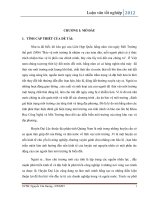
The ability of lightning strike to the lines depends significantly on the objects (trees,
buildings) located along the lines. The influence of objects near the line to the number of
times the lightning strikes directly on the overhead line is expressed through the shielding
factor Sf, the Sf is determined based on the distance from the external power line to
shielding objects based on Figure 2.1. Then, the number of times of lightning strikes to
overhead power line N S (times/km2/year) takes into account the shielding factor presented
by the expression:
28h 0,6 b
Ns N(1 S f ) Ng (
)(1 S f ) N gC f
10
With Cf is the line coefficient related to the surrounding shielding:
Cf = (28h-0,6+b).(1- Sf).10-1
(2.90)
(2.91)
Figure 2.1: Shielding factor by objects near the overhead line [6]
2.2. Improved method of risk assessment of damages due to lightning
2.2.1. Reason to improve
In the risk assessment standards as mentioned in section 2.1.1, 2.1.2, 2.1.3, each of
the standard has the advantages and approaches of risk assessment according to those
different directions.
IEC 62305-2 is an international standard with a more general level of risk
assessment that can be applied to many different structure in different regions. However,
in the process of calculating the standard risk assessment IEC 62305-2 [1], there are some
factors are retrieved from the lookup tables, not detailed in some input parameters but other
criteria have been considered, such as: Probability of a dangerous discharge based on
structure type [3]; the number of service lines connected to the structure [3] and the factor
related to the characteristics of the line (the height of the pole, the distance between the
two outer phase wires) takes into account the shielding object around the line [6].
AS/NZS 1768 [3] is based on the principles of risk assessment due to lightning
according to IEC 61662 standard but has been simplified, reducing the number of input
parameters so simple calculation method, because this is the standard that applies to the
country. However, in the risk calculation of the standard, there are a number of calculation
NCS: Lê Quang Trung
15
components that are calculated in detail for the types of structure taking into the different
construction materials and the number of service connection lines.
IEEE 1410 standard [6] is the standard of the American Association of Electrical
and Electronic Engineers, when calculating the number of lightning strikes on the power
line, the characteristics of the power line (the height of the pole, the distance between the
two outer phase wires), the object shielding around the line.
With the above analysis, it is found that the method of risk assessment of damages
due to lightning according to IEC 62305-2 [1] is more popular, international in comparison
with the other two standards. Therefore, the IEC 62305-2 standard was chosen as the basis
for the study to propose methods to improve the calculation and risk assessment of damages
due to lightning.
2.2.2 Determine the value of coefficients with the detailed calculation level which are
referenced and proposed from the AS/NZS 1768 and IEEE 1410 standard.
2.2.2.1. The probability of a dangerous discharge based on structure material types when
calculating the probability of PA for the risk component of RA
In standard [1], when calculating risk components related to human life's damage
by electric shock due to lightning strikes on structure RA. The probability of injury to living
beings by electric shock by step and touch voltages due to lightning strikes on structure P A
only consider two components:
- PTA is the probability depends on additional protection measures against touch and
step voltages, Table 2 - Annex 1.
- Pb is the probability depends on the lightning protection level, Table 3 - Annex 1.
The probability PA is calculated according to the expression (2.9).
In the standard [3], when calculating a risk component by touch and step voltages
to living beings outside the building due to lightning strikes on structure Rh (Rh equivalent
to the risk component of RA in the standard [1]). The value of probability by touch and step
voltages due to lightning strikes on structure Ph (Ph is equivalent to PA in standard [1]) but
takes into account three components (in addition to 2 components equivalent to calculating
PA [1], consider Ps component, specifically:
Ph Probability that lightning will cause a shock to animals or human beings outside
the structure due to dangerous step and touch potentials (Ph = PTA in standard [1]);
- k1 is the coefficient that depends on lightning protection system level when lightning
strike on structure (coefficient k1 = PB in standard [1]) with k1=1- E and E is efficiency of
lightning protection system on the structure, Table 1 - Annex 2;
- Ps is the probability of a dangerous discharge based on structure type, Table 2 Annex 2. The probability value Ph is defined as in the expression (2.49).
Through specific analysis of the standard [1] and [3], when lightning strikes on the
structure, the construction material of the structure is also one of the important factors that
directly affect the level of risk causing damage to human life inside the building, the
calculation of the PA probability for the risk of RA component in the standard [1] needs to
be further elaborated the probability of a dangerous discharge based on structure type P s is
referenced from the standard [3]. The probability value of P A is determined by the
following expression:
PA = PTA x PB x Ps
(2.92)
In the expression (2.92) the P TA value is determined according to Table 2 - Annex
1, the PB value is determined, Table 3 - Annex 1, the determined Ps value, Table 2 - Annex
2.
2.2.2.2. The shielding factor when calculating the number of lightning strikes directly and
indirectly on the service line connecting to the structure
NCS: Lê Quang Trung
16
In the standard [1], when calculating the number of direct lightning strikes, such as
in the expression (2.19) and the number of indirect lightning strikes Nl as in the expression
(2.27) for the overhead power lines mentioned the installation factor of the line C l, line
type factor CT and environment factor CE are retrieved from the lookup table (Table 8 Appendix 1) depending on the line installed in rural or suburban , urban or urban areas with
surrounding structures higher than 20m.
In the IEEE 1410 standard [6], when calculating the number of lightning strikes
directly on the service line which is determined by the expression (2.90) taking into account
the lightning density, the way to install the power line and the shielding objects near the
power line. In which, Cf is the factor of how to install the power line and shielding objects
near the power line determined by the expression (2.91).
Based on the content of the CE factor analysis of the standard [1] and the Cf factor
of the standard [6], the meaning of the two factors is the same but the value of C f in the
standard [6] detailed calculation and compliance with the actual conditions of the power
line than the CE value from the lookup table. Therefore, in order to calculate the number of
lightning strikes directly and indirectly on the power line in accordance with the actual
conditions at the place where the line is installed, the CE factors are proposed by the Cf
factor with the calculated level details in the expression (3.91) are referenced from standard
[6] to replace expressions (3.19) and (3.27) to calculate:
The number of the lightning strikes directly on the overhead line is determined by
the expression (2.93):
NL = NG x AL x Cl x Cf x CT x 10-6 (times/km2/year)
(2.93)
The number of the lightning strikes indirectly on the overhead line is determined by
the expression (2.94):
Nl = NG x Al x Cl x Cf x CT x 10-6 (times /km2/year)
(2.94)
2.2.2.3. Number of service lines when calculating probability related to lightning strikes
directly and indirectly on service lines connecting to the structure
In the standard [1], when calculating the risk related injury to living beings due to
electric shock when lightning strikes directly on service lines connecting to the structure
for the RU risk component. The value of the probability of lightning strike to the service
lines directly causes the surge into the structure causing damage to human life P U, the PU
probability value is calculated by the expression (2.21).
When calculating risks related to physical damage when lightning strikes directly
on service lines connecting to structure risk component RV. In the standard [1], the value
of the probability of lightning strike to the service lines directly causes material damage
PV, the PV probability value is calculated according to the expression (2.23).
Similarly, when calculating risks associated with damage to internal systems when
lightning strikes directly on service lines connecting to risk component RW. The probability
value of lightning strikes directly on service lines causes damage to the systems inside P W,
PW probability value is calculated according to the expression (2.25).
And when calculating risks associated with damage to internal systems while
lightning strikes near service lines connecting to the structure with risk component R Z, the
probability value of lightning near service lines causes failed systems inside the structure
PZ, PZ probability values are calculated according to the expression (2.29).
Meanwhile, in the standard [3], when calculating the risk factors caused by lightning
strikes directly or indirectly on service lines causing overvoltage on service lines entering
the structure: Rg component risk related to damage to life (Rg is equivalent to risk
component R U in standard [1]); Rc component risks related to physical damage (Rc is
equivalent to the P V risk component in the standard [1]); Re component risks involve
NCS: Lê Quang Trung
17
internal system failures due to direct lightning strikes on service lines (Re equivalent to RW
risk components in the standard [1]); The risk of Rl component relates to the failure of
internal systems due to indirect lightning strikes on service lines (Rl is equivalent to the RZ
risk component in the standard [1]). The probabilities of lightning hitting directly or
indirectly on service lines cause overvoltage on service lines entering the building
considering the number of overhead lines noh or the number or underground lines nug that
connect to the structure as in the expression (2.70), (2.71), (2.72), (2.73).
Therefore, if there are many service lines connecting to the structure on separate
lines, the probability of lightning strike directly or indirectly to the service lines will cause
overvoltage on the service lines go into the structure and the risk of damage due to lightning
will be different. In order to calculate in more detail according to actual conditions, the
calculated values of P U, PV, PW and PZ for component risks in the standard [1] need to
consider the number of connecting service lines connected to the structure [3] and the
proposed calculation is as follows:
PU/oh = PTU x PEB x PLD x CLD x noh
(2.95)
PV/oh = PEB x PLD x CLD x noh
(2.96)
PW/oh = PSPD x PLD x CLD x noh
(2.97)
Pz/oh = PSPD x PLI x CLI x noh
(2.98)
Expressions for the probability of P U, PV, PW and PZ for underground lines are as
follows:
PU/ug = PTU x PEB x PLD x CLD x nug
(2.99)
PV/ug = PEB x PLD x CLD x nug
(2.100)
PW/ug = PSPD x PLD x CLD x nug
(2.111)
Pz/ug= PSPD x PLI x CLI x nug
(2.102)
The factors of PTU, PEB, PLD and CLD are defined as in the standard [1]; Noh is the
number of overhead service lines and nug is the number of underground service lines
connected to a specified building in the standard [3].
NCS: Lê Quang Trung
18
2.2.2.4. Table of improved factors
Table 2.1: Table of improved factors
No.
1
2
3
Additional
Standard [1]
considerations/changes
The probability of a dangerous
discharge based on structure
material types when calculating PA = PTA . PB
the probability of PA for the risk
component of RA
The shielding factor when
NL = NG x AL x Cl x CE x CT x 10-6
calculating the number of
lightning strikes directly and
indirectly on the service line Nl = NG x Al x C l x CE x CT x 10-6
connecting to the structure
PU = PTU x PEB x PLD x CLD
Number of service lines when PV = PEB x PLD x CLD
calculating probability related
(3.96)
to lightning strikes directly and PW = PSPD x PLD
x CLD
indirectly on service lines
connecting to the structure
Pz = PSPD x PLI x CLI
Reference standards
Standard [3]:
Ph= k1 x Ph x Ps
Standard [6]:
NL = NG x Cf x 10-6
Với: C f = (b + 28 x h0,6) x 10-1 (1 - Sf)
Standard [3]:
Pc1p = nohp x k5 x Peo
Pc1 = noh x k5 x Pe1
Standard [3]:
Pc2p = nugp x k5 x Peo
Pc2 = nug x k5 x Pe2
Suggestions for improvement (*)
PA = PTA x PB x Ps
NL = NG .AL .Cl. Cf .CT .10-6
Với: C f = (b + 28.h0,6) x10-1 (1 - Sf)
Nl = NG x Al x Cl x C f x CT x 10-6
Với: C f = (b + 28 x h0,6) x 10-1 (1 - Sf)
PU/oh = PTU x PEB x PLD x CLD x noh
PV/oh = PEB x PLD x C LD x noh
PW/oh = PSPD x PLD x CLD x noh
Pz/oh = PSPD x PLI x C LI x noh
PU/ug = PTU x PEB x PLD x CLD xnug
PV/ug = PEB x PLD x C LD x nug
PW/ug = PSPD x PLD x CLD x nug
Pz/ug = PSPD x PLI x C LI x nug
(*)
k1 is the reducing factor for lightning protection system level; Ph is the probability that lightning will cause a shock to animals or human beings outside the structure due
to dangerous step and touch potentials; Ps is the probability of a dangerous discharge based on structure type; Cf is the factor of how to install the power line and shielding
objects near the power line determined by the expression; Sf shielding factor; noh is the number of the overhead lines connected to the structure; nug noh is the number of the
undergound lines connected to the structure.
NCS: Lê Quang Trung
19
2.2.3. Procedure for risk assessment
Identify the structure to be
protected
Identify the types of loss relevant to the structure
For each type of loss determine the tolerable risk RT
Identify and calculate the risk components R = RD + RI
R > RT
Yes
Yes
Structure is protected
No
No
Intall adequate protection measures to reduce R
Figure 2.2: Procedure for risk assessment
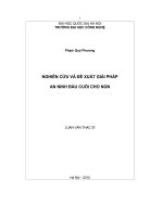
2.2.4. Calculation of the risk of damage due to lightning for the sample structure
2.2.4.1. Basic parameters of sample structure
Calculation of risk assessment of damage due to lightning for a commercial building in
Ho Chi Minh City; structure dimensions: 20×15×35m; lightning density: 12 (times/km2 /year),
no other buildings nearby; power line has a length of 200m, overhead; telecommunication
cable has a length of 1000m, underground .
H = 35m
ng dây đi n (trên không)
LP = 200m
W = 15m
ng dây vi n thông (đi ng m)
LT = 1000m
Figure 2.3: The structure need to assess the risk of damage due to lightning
2.2.4.2. The results of risk assessment
Steps to calculate the risk of damage due to lightning for the structure according to the
standard [1] and the improved method of risk assessment are proposed, the calculation results
are shown in Table 2.2.
NCS: Lê Quang Trung
20
Table 2.2: The risks value of the structure
Type of risk of damage
Risk of loss of a human life R1
Risk of loss of economic value R 4
IEC – 62305 [1]
3,75.10-5
0,255
Improved method
3,256.10-5
0,227
Errors (%)
13%
11%
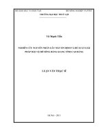
2.2.5. The program calculates the risk assessment of damage caused by lightning
The program calculates the risk assessment LIRISAS has the interface as shown in
Figure 4, based on the application of optimal parameters of risk assessment on a standard basis
[1] with improvement suggestions as shown in Table 2.1. The program allows users to enter
the necessary parameters related to the structure, the program will calculate the results of the
risk value of damage caused by lightning for the structure.
CHƯƠNG TRÌNH TÍNH TOÁN ĐÁNH GIÁ RỦI RO THIỆT HẠI DO SÉT LIRISAS
Phương pháp cải tiến theo tiêu chuẩn IEC-62305
Kích thước cấu trúc và các yếu tố môi trường
Đường dây dịch vụ
Đường dây điện
Chiều dài (m)
20
Chiều rộng (m)
15
Chiều dài (m)
Chiều cao (m)
35
Số l ợng đ
Mật độ sét khu vực (l n/km2 /năm)
12
Cách lắp đặt
Môi tr
ng xung quanh cấu trúc
Cô lập
Các dạng rủi ro
Loại đ
ng dây
Thiệt hại về con người
200
Dạng cấu trúc thi t hại về con ng
1
Dạng cấu trúc thi t hại về vật chất
Công nghiệp
Dạng cấu trúc thi t hại h thống bên trong
Không xem xét
Trên không
Tất cả
i
Hạ thế/viễn thông
ng dây
Thiệt hại về dịch vụ
Bi n pháp nối đất, cách ly theo IEC 62305-4
Không có
Đặc điểm của cấu trúc và các biện pháp bảo vệ
Bảo v đ
Vật li u xây dựng cấu trúc
ng dây bên trong cấu trúc
Gạch ceramic
Rủi ro cháy
Thấp
Không xem xét
Dạng cấu trúc thi t hại h thống bên trong
Không xem xét
Không có che chắn
Bêtông cốt thé p
Vật li u sàn
Dạng cấu trúc thi t hại về vật chất
Đường dây viễn thông
Chiều dài (m)
Bi n pháp bảo v phòng cháy
Xác suất phóng đi n sét gây cháy
Mức thấp
H số suy giảm phòng cháy
Không có
ng dây
Thiệt hại về giá trị kinh tế
Loại đ
Đi ngầm
Bi n pháp nối đất, cách ly theo IEC 62305-4
Không có
Cấp độ SPD đ ợc thiết kế
Không có
Bảo v đ
SPD ở ngõ vào thiết bị
Dạng cấu trúc thi t hại về vật nuôi
Tất cả
Dạng cấu trúc thi t hại về vật chất
Thương mại
Dạng cấu trúc thi t hại h thống bên trong
Trường học, thương mại
Hạ thế/viễn thông
ng dây
Thấp
Cấp độ bảo v chống sét
ng dây dịch vụ
Không xem xét
1
Cách lắp đặt
SPD ở ngõ vào đ
Dạng cấu trúc thi t hại về vật chất
Không có
Số l ợng đ
Mức độ hoản sợ khi có sự cố
Thiệt hại về di sản văn hóa
1000
ng dây bên trong cấu trúc
Không có
Không có che chắn
Không có
Không có
Kết quả tính toán mức độ rủi ro
Giá trị rủi ro tính toán
Giá trị rủi ro chấp nhận đ ợc
Thiệt hại về con người
Thiệt hại về dịch vụ
3.25678E-05
0
0
0.2276893
0.00001
0.001
0.0001
0.001
Thiệt hại về di sản văn hóa
Thiệt hại về giá trị kinh tế
Figure 2.4: The interface of the program calculates the risk assessment of damage
caused by lightning LIRISAS
2.3. Conclusions
On the basis of the calculation method of risk assessment due to lightning according to
IEC 62305-2, the improved method has a more detailed level, taking into account the factor:
probability of a dangerous discharge based on structure type, the number of service lines
connected to the structure, considering the way to install the line and shielding objects along
the power lines connected to the structure. The calculation results with the sample structure
show that there is a significant difference in the value of risk of loss of a human life
R1 (about 13% lower), and the value of risk of loss of economic R4 (about 11% lower).
NCS: Lê Quang Trung
21
Chapter 3
IMPROVED SURGE GENERATOR MODEL AND SURGE
PROTECTIVE DEVICE MODEL ON THE
LOW VOLTAGE POWER LINE
3.1. Surge generator model
3.1.1. The reasons for improving
Up to now, there are many domestic and international research projects on lightning
surge generator model but only focus on each type of lightning surge separately and have
relatively large errors compared to standard lightning surges. Meanwhile, the inspection of the
type of lightning protection devices on the low voltage power lines should be carried out with
many different types of lightning surges. Therefore, the study proposes an improved lightning
pulse model that produces many different types of lightning surges, which are highly accurate
compared to standard lightning surges to facilitate the use of equipment testing is necessary.
3.1.2. Mathematical model
3.1.2.1. Mathematical model of Heidler
The Heidler equation is used to describe lightning surges [57]:
i(t) =
(t/τ1 )10
I0
η
1+(t/τ1 )10
e(−t/τ2)
(3.1)
Where I0 is the value of peak current (kA), η is the correction factor for the peak current τ1 is
the front time constant, τ2 is the tail time constant.
Parameters τ1, τ2 and are determined by the time of increase of tds and the time of
reduction of ts of the lightning current surge.
The rise and fall time of lightning current surge form is specified as follows:
tds = 1,25(t2 – t1)
(3.2)
ts = t5 – t1+0.1tds
(3.3)
3.1.2.2. Determine parameters for Heidler's equation:
The current is considered to be the product of two time-response functions (increasing
time function x(t) and decrease time function y(t)). Establish the function of the current as
follows [64]:
i(t) = I0.x(t).y(t)
(3.4)
Where: x(t) =
(t/τ1 )10
1+(t/τ1 )10
y(t) = e(−t/τ2)
Applying the approximation method during increasing current surge, the value of
current function decreases y(t)=1. Similarly, when the current is reduced, the value of the
current function increases x(t)=1 [64].
In the process of increasing current (wave phase), equation (3.1) takes the form:
i(t)=
I0
η
(t/τ1 )10
1+(t/τ1 )10
e(−t/τ2)
(3.5)
At t = t1 the current value i(t) = 0,1I, inferred:
NCS: Lê Quang Trung
22
t1 / τ1 10 0,1 0,9 t / τ 10 0,1
1 1
t1 / τ1 10 1
(3.6)
(3.7)
Hence:
t1 1 / 9.τ1
And at t = t2 the current value i(t) = 0,9I0, inferred:
10
t 2 / τ1 10 0,9 0,1 t / τ 10 0,9
2 1
t 2 / τ1 10 1
(3.8)
Hence: t 2 10 9.τ1
From there:
(3.9)
t 2 t1 0,8t ds (10 9 10 1 / 9).τ1
0,8.t
τ1 = 10 10ds
1,88t ds
( 9 - 1 / 9)
(3.10)
(3.11)
Similarly, in the process of current attenuation current, the current function is
determined approximately by the following expression:
t
(− )
i(t) = I0 e τ2
When t = t5 the current value i(t) = 0,5I0
Hence:
I0 e
t5
τ2
t
(− 5 )
τ2
(3.12)
= 0.5I0
(3.13)
= ln2
(3.14)
t5
τ2 =
(3.15)
ln2
When t > 0, x(t) < 1, the maximum current is lower than I0. Therefore, the peak current
correction factor η is determined by the value calculation formula (3.16) [57]:
η
1
τ1 / τ 2 .10 10τ 2 / τ1
e
(3.16)
Calculated results τ1, τ2, η according to the expressions (3.11), (3.15) and (3.16),
corresponding to the different types of lightning impulses presented, Table 3.1.
Table 3.1: Calculated parameter values with standard lightning current surge
tds(µs)
ts(µs)
𝛕𝟏(s)
η
𝛕𝟐(s)
ta(s)
tb(s)
e1(%) e2(%)
10
350
1.8800e-05 4.9052e-04 9.3533e-01 9.8750e-06 3.6039e-04 1.25
2.97
1
5
1.8800e-06 5.7708e-06 6.3204e-01 8.7500e-07 5.4875e-06 12.5
9.8
4
10
7.5200e-06 8.6562e-06 3.2983e-01 3.1250e-06 1.1013e-05 21.88 10,13
8
20
1.5040e-05 1.7312e-05 3.2983e-01 6.2500e-06 2.1825e-05 21.88 9.0
Where: ta is the front time calculation, tb is the tail time calculation, η is the correction factor, e1, e2 is
respectively error of front and tail time.
e1= 100% −
NCS: Lê Quang Trung
𝑡𝑎∗100%
𝑡𝑑𝑠
e2= 100% −
𝑡𝑏 ∗100%
𝑡𝑠
23