Tiêu chuẩn thí nghiệm rơ le hệ thống điện IEC 60255 127
Bạn đang xem bản rút gọn của tài liệu. Xem và tải ngay bản đầy đủ của tài liệu tại đây (1.16 MB, 54 trang )
®
Edition 1.0
INTERNATIONAL
STANDARD
NORME
INTERNATIONALE
Measuring relays and protection equipment –
Part 127: Functional requirements for over/under voltage protection
IEC 60255-127:2010
Relais de mesure et dispositifs de protection –
Partie 127: Exigences fonctionnelles pour les protections à minimum et
maximum de tension
2010-04
Copyrighted material licensed to Electricity of Vietnam by Thomson Scientific, Inc. (www.techstreet.com). This copy downloaded on 2014-12-24 02:15:32 -0600 by authorized user Quach Lam hung.
No further reproduction or distribution is permitted.
IEC 60255-127
Copyright © 2010 IEC, Geneva, Switzerland
All rights reserved. Unless otherwise specified, no part of this publication may be reproduced or utilized in any form or by
any means, electronic or mechanical, including photocopying and microfilm, without permission in writing from either IEC or
IEC's member National Committee in the country of the requester.
If you have any questions about IEC copyright or have an enquiry about obtaining additional rights to this publication,
please contact the address below or your local IEC member National Committee for further information.
Droits de reproduction réservés. Sauf indication contraire, aucune partie de cette publication ne peut être reproduite
ni utilisée sous quelque forme que ce soit et par aucun procédé, électronique ou mécanique, y compris la photocopie
et les microfilms, sans l'accord écrit de la CEI ou du Comité national de la CEI du pays du demandeur.
Si vous avez des questions sur le copyright de la CEI ou si vous désirez obtenir des droits supplémentaires sur cette
publication, utilisez les coordonnées ci-après ou contactez le Comité national de la CEI de votre pays de résidence.
IEC Central Office
3, rue de Varembé
CH-1211 Geneva 20
Switzerland
Email:
Web: www.iec.ch
About the IEC
The International Electrotechnical Commission (IEC) is the leading global organization that prepares and publishes
International Standards for all electrical, electronic and related technologies.
About IEC publications
The technical content of IEC publications is kept under constant review by the IEC. Please make sure that you have the
latest edition, a corrigenda or an amendment might have been published.
Catalogue of IEC publications: www.iec.ch/searchpub
The IEC on-line Catalogue enables you to search by a variety of criteria (reference number, text, technical committee,…).
It also gives information on projects, withdrawn and replaced publications.
IEC Just Published: www.iec.ch/online_news/justpub
Stay up to date on all new IEC publications. Just Published details twice a month all new publications released. Available
on-line and also by email.
Electropedia: www.electropedia.org
The world's leading online dictionary of electronic and electrical terms containing more than 20 000 terms and definitions
in English and French, with equivalent terms in additional languages. Also known as the International Electrotechnical
Vocabulary online.
Customer Service Centre: www.iec.ch/webstore/custserv
If you wish to give us your feedback on this publication or need further assistance, please visit the Customer Service
Centre FAQ or contact us:
Email:
Tel.: +41 22 919 02 11
Fax: +41 22 919 03 00
A propos de la CEI
La Commission Electrotechnique Internationale (CEI) est la première organisation mondiale qui élabore et publie des
normes internationales pour tout ce qui a trait à l'électricité, à l'électronique et aux technologies apparentées.
A propos des publications CEI
Le contenu technique des publications de la CEI est constamment revu. Veuillez vous assurer que vous possédez
l’édition la plus récente, un corrigendum ou amendement peut avoir été publié.
Catalogue des publications de la CEI: www.iec.ch/searchpub/cur_fut-f.htm
Le Catalogue en-ligne de la CEI vous permet d’effectuer des recherches en utilisant différents critères (numéro de référence,
texte, comité d’études,…). Il donne aussi des informations sur les projets et les publications retirées ou remplacées.
Just Published CEI: www.iec.ch/online_news/justpub
Restez informé sur les nouvelles publications de la CEI. Just Published détaille deux fois par mois les nouvelles
publications parues. Disponible en-ligne et aussi par email.
Electropedia: www.electropedia.org
Le premier dictionnaire en ligne au monde de termes électroniques et électriques. Il contient plus de 20 000 termes et
définitions en anglais et en français, ainsi que les termes équivalents dans les langues additionnelles. Egalement appelé
Vocabulaire Electrotechnique International en ligne.
Service Clients: www.iec.ch/webstore/custserv/custserv_entry-f.htm
Si vous désirez nous donner des commentaires sur cette publication ou si vous avez des questions, visitez le FAQ du
Service clients ou contactez-nous:
Email:
Tél.: +41 22 919 02 11
Fax: +41 22 919 03 00
Copyrighted material licensed to Electricity of Vietnam by Thomson Scientific, Inc. (www.techstreet.com). This copy downloaded on 2014-12-24 02:15:32 -0600 by authorized user Quach Lam hung.
No further reproduction or distribution is permitted.
THIS PUBLICATION IS COPYRIGHT PROTECTED
®
Edition 1.0
2010-04
INTERNATIONAL
STANDARD
NORME
INTERNATIONALE
Measuring relays and protection equipment –
Part 127: Functional requirements for over/under voltage protection
Relais de mesure et dispositifs de protection –
Partie 127: Exigences fonctionnelles pour les protections à minimum et
maximum de tension
INTERNATIONAL
ELECTROTECHNICAL
COMMISSION
COMMISSION
ELECTROTECHNIQUE
INTERNATIONALE
PRICE CODE
CODE PRIX
ICS 29.120.70
® Registered trademark of the International Electrotechnical Commission
Marque déposée de la Commission Electrotechnique Internationale
T
ISBN 978-2-88910-077-4
Copyrighted material licensed to Electricity of Vietnam by Thomson Scientific, Inc. (www.techstreet.com). This copy downloaded on 2014-12-24 02:15:32 -0600 by authorized user Quach Lam hung.
No further reproduction or distribution is permitted.
IEC 60255-127
60255-127 © IEC:2010
CONTENTS
FOREWORD...........................................................................................................................4
1
Scope and object..............................................................................................................6
2
Normative references .......................................................................................................6
3
Terms and definitions .......................................................................................................6
4
Specification of the function..............................................................................................8
4.1
4.2
4.3
4.4
5
General ...................................................................................................................8
Input energising quantities/Energising quantities .....................................................8
Binary input signals .................................................................................................9
Functional logic .......................................................................................................9
4.4.1 Operating characteristics .............................................................................9
4.4.2 Reset characteristics ................................................................................. 13
4.5 Binary output signals ............................................................................................. 14
4.5.1 Start (pick-up) signal ................................................................................. 14
4.5.2 Operate (trip) signal................................................................................... 15
4.5.3 Other binary output signals ........................................................................ 15
Performance specification .............................................................................................. 15
5.1
5.2
5.3
5.4
6
Accuracy related to the characteristic quantity....................................................... 15
Accuracy related to the operate time ..................................................................... 15
Accuracy related to the reset time ......................................................................... 16
Transient performance .......................................................................................... 16
5.4.1 Overshoot time .......................................................................................... 16
5.4.2 Response to time varying value of the characteristic quantity .................... 16
5.5 Voltage transformer requirements ......................................................................... 16
Functional test methodology ........................................................................................... 16
6.1
6.2
7
General ................................................................................................................. 16
Determination of steady state errors related to the characteristic quantity ............. 17
6.2.1 Accuracy of setting (start) value ................................................................ 17
6.2.2 Reset ratio determination........................................................................... 18
6.3 Determination of steady state errors related to the start and operate time ............. 18
6.4 Determination of steady state errors related to the reset time ................................ 19
6.5 Determination of transient performance ................................................................. 20
6.5.1 Overshoot time for undervoltage protection ............................................... 20
6.5.2 Response to time varying value of the characteristic quantity for
dependent time relays ............................................................................... 20
Documentation requirements .......................................................................................... 21
7.1 Type test report ..................................................................................................... 21
7.2 Other user documentation ..................................................................................... 22
Annex A (informative) Reset time determination for relays with trip output only.................... 23
Bibliography.......................................................................................................................... 24
Figure 1 – Simplified protection function block diagram...........................................................8
Figure 2 – Overvoltage independent time characteristic .......................................................... 9
Figure 3 – Undervoltage independent time characteristic ...................................................... 10
Figure 4 – Dependent time characteristic for overvoltage protection ..................................... 11
Figure 5 – Dependent time characteristic for undervoltage protection ................................... 12
Copyrighted material licensed to Electricity of Vietnam by Thomson Scientific, Inc. (www.techstreet.com). This copy downloaded on 2014-12-24 02:15:32 -0600 by authorized user Quach Lam hung.
No further reproduction or distribution is permitted.
–2–
–3–
Figure 6 – Definite time reset characteristic .......................................................................... 14
Figure 7 – Definite time reset characteristic (alternative solution with instantaneous
reset after relay operation).................................................................................................... 14
Figure 8 – Test waveform ..................................................................................................... 21
Figure A.1 – Dependent reset time determination ................................................................. 23
Table 1 – Test points for overvoltage elements ..................................................................... 19
Table 2 – Test points for undervoltage elements ................................................................... 19
Table 3 – Test points for overvoltage elements ..................................................................... 20
Table 4 – Test points for undervoltage elements ................................................................... 20
Table 5 – Recommended values for the test ......................................................................... 21
Copyrighted material licensed to Electricity of Vietnam by Thomson Scientific, Inc. (www.techstreet.com). This copy downloaded on 2014-12-24 02:15:32 -0600 by authorized user Quach Lam hung.
No further reproduction or distribution is permitted.
60255-127 © IEC:2010
INTERNATIONAL ELECTROTECHNICAL COMMISSION
____________
MEASURING RELAYS AND PROTECTION EQUIPMENT –
Part 127: Functional requirements for over/under voltage protection
FOREWORD
1) The International Electrotechnical Commission (IEC) is a worldwide organization for standardization comprising
all national electrotechnical committees (IEC National Committees). The object of IEC is to promote
international co-operation on all questions concerning standardization in the electrical and electronic fields. To
this end and in addition to other activities, IEC publishes International Standards, Technical Specifications,
Technical Reports, Publicly Available Specifications (PAS) and Guides (hereafter referred to as “IEC
Publication(s)”). Their preparation is entrusted to technical committees; any IEC National Committee interested
in the subject dealt with may participate in this preparatory work. International, governmental and nongovernmental organizations liaising with the IEC also participate in this preparation. IEC collaborates closely
with the International Organization for Standardization (ISO) in accordance with conditions determined by
agreement between the two organizations.
2) The formal decisions or agreements of IEC on technical matters express, as nearly as possible, an international
consensus of opinion on the relevant subjects since each technical committee has representation from all
interested IEC National Committees.
3) IEC Publications have the form of recommendations for international use and are accepted by IEC National
Committees in that sense. While all reasonable efforts are made to ensure that the technical content of IEC
Publications is accurate, IEC cannot be held responsible for the way in which they are used or for any
misinterpretation by any end user.
4) In order to promote international uniformity, IEC National Committees undertake to apply IEC Publications
transparently to the maximum extent possible in their national and regional publications. Any divergence
between any IEC Publication and the corresponding national or regional publication shall be clearly indicated in
the latter.
5) IEC itself does not provide any attestation of conformity. Independent certification bodies provide conformity
assessment services and, in some areas, access to IEC marks of conformity. IEC is not responsible for any
services carried out by independent certification bodies.
6) All users should ensure that they have the latest edition of this publication.
7) No liability shall attach to IEC or its directors, employees, servants or agents including individual experts and
members of its technical committees and IEC National Committees for any personal injury, property damage or
other damage of any nature whatsoever, whether direct or indirect, or for costs (including legal fees) and
expenses arising out of the publication, use of, or reliance upon, this IEC Publication or any other IEC
Publications.
8) Attention is drawn to the Normative references cited in this publication. Use of the referenced publications is
indispensable for the correct application of this publication.
9) Attention is drawn to the possibility that some of the elements of this IEC Publication may be the subject of
patent rights. IEC shall not be held responsible for identifying any or all such patent rights.
International Standard IEC 60255-127 has been prepared by IEC technical committee 95:
Measuring relays and protection equipment.
The text of this standard is based on the following documents:
CDV
Report on voting
95/254/CDV
95/261/RVC
Full information on the voting for the approval of this standard can be found in the report on
voting indicated in the above table.
This publication has been drafted in accordance with the ISO/IEC Directives, Part 2.
A list of all parts of the IEC 60255 series can be found, under the general title Measuring
relays and protection equipment, on the IEC website.
Copyrighted material licensed to Electricity of Vietnam by Thomson Scientific, Inc. (www.techstreet.com). This copy downloaded on 2014-12-24 02:15:32 -0600 by authorized user Quach Lam hung.
No further reproduction or distribution is permitted.
60255-127 © IEC:2010
–4–
–5–
The committee has decided that the contents of this publication will remain unchanged until
the stability date indicated on the IEC web site under "" in the data
related to the specific publication. At this date, the publication will be
•
•
•
•
reconfirmed,
withdrawn,
replaced by a revised edition, or
amended.
Copyrighted material licensed to Electricity of Vietnam by Thomson Scientific, Inc. (www.techstreet.com). This copy downloaded on 2014-12-24 02:15:32 -0600 by authorized user Quach Lam hung.
No further reproduction or distribution is permitted.
60255-127 © IEC:2010
MEASURING RELAYS AND PROTECTION EQUIPMENT –
Part 127: Functional requirements for over/under voltage protection
1
Scope
This part of IEC 60255 specifies minimum requirements for over/under voltage relays. The
standard includes specification of the protection function, measurement characteristics and
time delay characteristics.
This standard defines the influencing factors that affect the accuracy under steady state
conditions and performance characteristics during dynamic conditions. The test
methodologies for verifying performance characteristics and accuracy are also included in this
standard.
The over/under voltage functions covered by this standard are as follows:
Phase undervoltage protection
Positive sequence undervoltage protection
Phase overvoltage protection
Residual/zero-sequence overvoltage protection
Negative sequence/ unbalance overvoltage protection
IEEE/ANSI C37.2
IEC 61850-7-4
Function numbers
Logical nodes
27
PTUV
27D
PTUV
59
PTOV
59N/59G
PTOV
47
PTOV
The general requirements for measuring relays and protection equipment are specified in
IEC 60255-1.
2
Normative references
The following referenced documents are indispensable for the application of this document.
For dated references, only the edition cited applies. For undated references, the latest edition
of the referenced document (including any amendments) applies.
IEC 60044 (all parts), Instrument transformers
IEC 60255-1, Measuring relays and protection equipment – Part 1: Common requirements
3
Terms and definitions
For the purposes of this document, the following terms and definition apply
3.1
theoretical curve of time versus characteristic quantity
curve which represents the relationship between the theoretical specified operate time and
the characteristic quantity
Copyrighted material licensed to Electricity of Vietnam by Thomson Scientific, Inc. (www.techstreet.com). This copy downloaded on 2014-12-24 02:15:32 -0600 by authorized user Quach Lam hung.
No further reproduction or distribution is permitted.
60255-127 © IEC:2010
–6–
–7–
3.2
curves of maximum and minimum limits of the operate time
curves of the limiting errors on either side of the theoretical time vs. characteristic quantity
which identify the maximum and minimum operate times corresponding to each value of the
characteristic quantity
3.3
setting value (start) of the characteristic quantity
GS
the reference value used for the definition of the theoretical curve of time vs. characteristic
quantity
3.4
start time
duration of the time interval between the instant when the characteristic quantity of the
measuring relay in reset condition is changed, under specified conditions, and the instant
when the start signal asserts
3.5
operate time
duration of the time interval between the instant when the characteristic quantity of a
measuring relay in reset condition is changed, under specified conditions, and the instant
when the relay operates
[IEC 60050-447:2010, 447-05-05]
3.6
disengaging time
duration of the time interval between the instant a specified change is made in the value of
the input energizing quantity which will cause the relay to disengage and the instant it
disengages
[IEC 60050-447:2010, 447-05-10]
3.7
reset time
duration of the time interval between the instant when the characteristic quantity of a
measuring relay in operate condition is changed, under specified conditions, and the instant
when the relay resets
[IEC 60050-447:2010, 447-05-06]
3.8
overshoot time
the difference between the operate time of the relay at the specified value of the input
energising quantity and the maximum duration of the value of input energising quantity which,
when suddenly reduced (for the overvoltage relay)/increased(for the undervoltage relay) to a
specified value below(for the overvoltage relay)/above(for the undervoltage relay) the setting
value, is insufficient to cause operation
3.9
threshold of independent time operation
GD
the value of the characteristic quantity at which the relay operate time changes from
dependent time operation to independent time operation
Copyrighted material licensed to Electricity of Vietnam by Thomson Scientific, Inc. (www.techstreet.com). This copy downloaded on 2014-12-24 02:15:32 -0600 by authorized user Quach Lam hung.
No further reproduction or distribution is permitted.
60255-127 © IEC:2010
60255-127 © IEC:2010
3.10
reset ratio
disengaging ratio
ratio between the voltage value at the point where the relay just ceases to start (start signal
changes from ON to OFF) and the actual start voltage of the element.
NOTE It is usually defined as a percentage such that for an overvoltage element the resetting ratio shall be less
than 100 % and for an undervoltage element the reset ratio shall be greater than 100 %.
4
Specification of the function
4.1
General
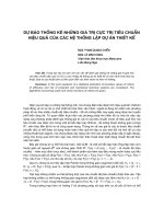
The protection function with its inputs, outputs, measuring element, time delay characteristics
and functional logic is shown in Figure 1. The manufacturer shall provide the functional block
diagram of the specific implementation.
IEC
743/10
Figure 1 – Simplified protection function block diagram
4.2
Input energising quantities/Energising quantities
The input energising quantities are the measuring signals, e.g. voltages. Their ratings and
relevant standards are specified in IEC 60255-1. Input energising quantities can come with
wires from voltage transformers or as a data packet over a communication port using an
appropriate communication protocol (such as IEC 61850-9-2).
The energising quantities used by the protection function need not be directly the voltage at
the secondary side of the voltage transformers. Therefore, the measuring relay documentation
shall state the type of energising quantities used by the protection function. Examples are:
•
single phase voltage measurement;
•
three phase voltage (phase to phase or phase to earth) measurement;
•
neutral to earth voltage or residual voltage measurement;
•
positive, negative or zero sequence voltage measurement.
The type of measurement of the energising quantity shall be stated. Examples are:
•
RMS value of the signal;
Copyrighted material licensed to Electricity of Vietnam by Thomson Scientific, Inc. (www.techstreet.com). This copy downloaded on 2014-12-24 02:15:32 -0600 by authorized user Quach Lam hung.
No further reproduction or distribution is permitted.
–8–
–9–
•
RMS value of the fundamental component of the signal;
•
RMS value of a specific harmonic component of the signal;
•
peak values of the signal;
•
instantaneous value of the signal.
4.3
Binary input signals
If any binary input signals (externally or internally driven) are used, their influence on the
protection function shall be clearly described on the functional logic diagram. Additional
textual description may also be provided if this can further clarify the functionality of the input
signals and their intended usage.
4.4
Functional logic
4.4.1
4.4.1.1
Operating characteristics
General
The relationship between operate time and characteristic quantity can be expressed by means
of a characteristic curve. The shape of this curve shall be declared by the manufacturer by an
equation (preferred) or by graphical means.
This standard specifies two types of characteristics:
•
independent time characteristic (i.e. definite time delay);
•
dependent time characteristic (i.e. inverse time delay).
The time characteristic defines the operate time which is the duration between the instant
when the input energising quantity crosses the setting value (G S ) and the instant when the
relay operates.
4.4.1.2
Independent time characteristic
Independent time characteristic is defined in terms of the setting value of the characteristic
quantity G S and the operate time t op . When no intentional time delay is used then the
independent time relay is denoted as an instantaneous relay.
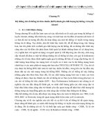
For overvoltage relays, t (G) = t op when G > G S . The independent time characteristic is
presented in Figure 2.
IEC
744/10
Figure 2 – Overvoltage independent time characteristic
Copyrighted material licensed to Electricity of Vietnam by Thomson Scientific, Inc. (www.techstreet.com). This copy downloaded on 2014-12-24 02:15:32 -0600 by authorized user Quach Lam hung.
No further reproduction or distribution is permitted.
60255-127 © IEC:2010
For undervoltage relays, t (G) = t op when G < G S . The independent time characteristic is
presented in Figure 3.
IEC
745/10
Figure 3 – Undervoltage independent time characteristic
4.4.1.3
Standard dependent time characteristics
For overvoltage protection, the characteristic curves of dependent time relays shall follow a
law of the form:
t (G ) =
T
⎛ G
⎜
⎜G
⎝ S
⎞
⎟ −1
⎟
⎠
where:
t (G)
is the theoretical operate time with constant value of G in seconds;
T
G
is the time setting (theoretical operate time for G = 2 × G S );
is the measured value of the characteristic quantity;
GS
is the setting value (see 3.3).
This dependent time characteristic is shown in Figure 4.
(1)
Copyrighted material licensed to Electricity of Vietnam by Thomson Scientific, Inc. (www.techstreet.com). This copy downloaded on 2014-12-24 02:15:32 -0600 by authorized user Quach Lam hung.
No further reproduction or distribution is permitted.
60255-127 © IEC:2010
– 10 –
– 11 –
t(G)
T
Effective range
G
GS
1,2
GD
2GS
´
IEC
GS
746/10
Figure 4 – Dependent time characteristic for overvoltage protection
The effective range of the characteristic quantity for the dependent time portion of the curve
shall lie between 1,2 × G S and G D . The value of G D shall be stated by the manufacturer for
the upper limit of the setting range.
For undervoltage protection, the characteristic curves of dependent time relays shall follow a
law of the form:
t (G ) =
T
⎛ G
1 − ⎜⎜
⎝ GS
⎞
⎟
⎟
⎠
where:
t (G)
is the theoretical operate time in seconds with constant value of G;
T
is the time setting (theoretical operate time for G = 0);
G
is the measured value of the characteristic quantity;
GS
is the setting value (see 3.3).
This dependent time characteristic is shown in Figure 5.
(2)
Copyrighted material licensed to Electricity of Vietnam by Thomson Scientific, Inc. (www.techstreet.com). This copy downloaded on 2014-12-24 02:15:32 -0600 by authorized user Quach Lam hung.
No further reproduction or distribution is permitted.
60255-127 © IEC:2010
t(G)
T
G
0
GS
Effective range
IEC
747/10
Figure 5 – Dependent time characteristic for undervoltage protection
The effective range of the dependent time portion of the characteristic quantity shall lie
between 0 and G S .
Power system fault conditions can produce time varying voltages. To ensure proper
coordination between dependent time relays under such conditions, relay behaviour shall be
of the form described by the integration given by Equation 3.
For G > G S (overvoltage protection) or G < G S (undervoltage protection):
T0
1
∫ t (G ) dt
=1
(3)
0
where:
T0
is the theoretical operate time where G varies with time;
t(G)
is the theoretical operate time with constant value of G in seconds;
G
is the measured value of the characteristic quantity.
Operate time is defined as the time instant when the integral in Equation 3 becomes equal to
or greater than one.
Copyrighted material licensed to Electricity of Vietnam by Thomson Scientific, Inc. (www.techstreet.com). This copy downloaded on 2014-12-24 02:15:32 -0600 by authorized user Quach Lam hung.
No further reproduction or distribution is permitted.
60255-127 © IEC:2010
– 12 –
4.4.2
4.4.2.1
– 13 –
Reset characteristics
General
To allow users to determine the behaviour of the relay in the event of repetitive intermittent
faults or for faults which may occur in rapid succession, relay resetting characteristics shall be
defined by the manufacturer. The recommended reset characteristics are defined below.
4.4.2.2
No intentional delay on reset
For undervoltage relays, for G > (reset ratio) × G S , the relay shall return to its reset state with
no intentional delay. This reset option can apply to both dependent and independent time
relays.
For overvoltage relays, for G < (reset ratio) × G S , the relay shall return to its reset state with
no intentional delay. This reset option can apply to both dependent and independent time
relays.
4.4.2.3
Definite time resetting
This reset characteristic is applicable to overvoltage and undervoltage protection. Here the
definite time reset is described for an overvoltage protection. The principle is the same for an
undervoltage protection.
For G < (reset ratio) × G S , the relay shall return to its reset state after a user-defined reset
time delay, t r . During the reset time, the element shall retain its state value as defined by
tP
1
∫ t (G)dt
with t P being the transient period during which G > G S . If during the reset time period,
0
the characteristic quantity exceeds G S , the reset timer t r, is immediately reset to zero and the
element continues normal operation starting from the retained value.
Following G > G S for a cumulative period causing relay operation, the relay shall maintain its
operated state for the reset time period after the operating quantity falls below G S as shown in
Figure 6. Alternatively, the relay may return to its reset state with no intentional delay as soon
as the operating quantity falls below G S after tripping as shown in Figure 7.
This reset option can apply to both dependent and independent time elements. A graphical
representation of this reset characteristic is shown in Figures 6 and 7, for partial and complete
operation of the element.
Copyrighted material licensed to Electricity of Vietnam by Thomson Scientific, Inc. (www.techstreet.com). This copy downloaded on 2014-12-24 02:15:32 -0600 by authorized user Quach Lam hung.
No further reproduction or distribution is permitted.
60255-127 © IEC:2010
Energising
quantity > Gs
Start time
Start (pick-up)
signal
Disengaging time
Operate
signal
Value of
internal time
delay counter
Time delay setting
tr Reset time setting
Tripping
tr
tr
tr
Reset time
Reset time
IEC
748/10
Figure 6 – Definite time reset characteristic
Energising
quantity > Gs
Start time
Start (pick-up)
signal
Disengaging time
Operate
signal
Value of
internal time
delay counter
Tripping
Time delay setting
tr Reset time setting
Reset time
tr
tr
Reset time
IEC
749/10
Figure 7 – Definite time reset characteristic
(alternative solution with instantaneous reset after relay operation)
4.5
4.5.1
Binary output signals
Start (pick-up) signal
The start signal is the output of measuring and threshold elements, without any intentional
time delay. If start signal is not provided, the manufacturer shall give information on how to
conduct testing related to start signal as defined in Clause 6.
Copyrighted material licensed to Electricity of Vietnam by Thomson Scientific, Inc. (www.techstreet.com). This copy downloaded on 2014-12-24 02:15:32 -0600 by authorized user Quach Lam hung.
No further reproduction or distribution is permitted.
60255-127 © IEC:2010
– 14 –
4.5.2
– 15 –
Operate (trip) signal
The operate signal is the output of measuring and threshold elements, after completion of any
intentional operating time delay. In the case of instantaneous elements, this signal may occur
at the same time as the start signal (if provided).
4.5.3
Other binary output signals
If any other binary output signals are available for use, their method of operation shall be
clearly shown on the functional logic diagram. Additional textual description may also be
provided if this can further clarify the functionality of the output signal and its intended usage.
5
Performance specification
5.1
Accuracy related to the characteristic quantity
For both independent and dependent time relays, the accuracy and the reset ratio related to
the characteristic quantity shall be declared by the manufacturer.
For both dependent and independent time relays, the manufacturer shall declare the accuracy
related to the characteristic quantity along with a setting value range over which it is
applicable.
5.2
Accuracy related to the operate time
For independent time relays, the maximum permissible error of the specified operate time
shall be expressed as either:
•
a percentage of the time setting value, or;
•
a percentage of the time setting value, together with a fixed maximum time error
(where this may exceed the percentage value), whichever is greater. For example,
± 5 % or ± 20 ms whichever is greater, or;
•
a fixed maximum time error
For dependent time relays, the reference limiting error is identified by an assigned error
declared by the manufacturer. For relays with a decreasing time function, the value of the
assigned error shall be declared at the maximum limit of the effective range of the dependent
time portion of the characteristic (G D) as a percentage of the theoretical time. The reference
limiting error shall be declared either as:
•
a theoretical curve of time plotted against multiples of the setting value of the
characteristic quantity bounded by two curves representing the maximum and
minimum limits of the limiting error over the effective range of the dependent time
portion of the characteristic or,
•
an assigned error claimed for the effective range of the dependent time portion of the
characteristic of the characteristic quantity.
For both dependent and independent time relays, the manufacturer shall declare the
maximum limiting error related to the operate time along with a setting range of time delay
over which it is applicable.
The manufacturer shall declare if the internal measurement time of the characteristic quantity
and the output contact operation time is included in the time delay setting or it is in addition to
the time delay setting.
Copyrighted material licensed to Electricity of Vietnam by Thomson Scientific, Inc. (www.techstreet.com). This copy downloaded on 2014-12-24 02:15:32 -0600 by authorized user Quach Lam hung.
No further reproduction or distribution is permitted.
60255-127 © IEC:2010
5.3
60255-127 © IEC:2010
Accuracy related to the reset time
For relays with no intentional reset delay, the manufacturer shall declare the reset time of the
element.
For relays with a definite time delay on reset, the maximum permissible error of the specified
reset time shall be expressed as either:
•
a percentage of the reset time setting value, or;
•
a percentage of the reset time setting value, together with a fixed maximum time error
(where this may exceed the percentage value), whichever is greater. For example,
± 5 % or ± 20 ms whichever is greater, or;
•
a fixed maximum time error.
The manufacturer shall declare the maximum limiting error related to the reset time along with
a setting range of time delay over which it is applicable.
The manufacturer shall declare if the internal measurement time (disengaging time) is
included in the reset time setting or it is in addition to the reset time setting.
5.4
Transient performance
5.4.1
Overshoot time
The manufacturer shall declare the overshoot time.
5.4.2
Response to time varying value of the characteristic quantity
To ensure proper coordination with dependent time relays, the relay performance under time
varying fault conditions (characteristic quantity varies with time) shall be tested. The
manufacturer shall declare any additional errors, but in all cases, the additional error shall be
less than 15 %.
5.5
Voltage transformer requirements
The manufacturer shall declare the types of the voltage transformers required to maintain the
claimed performance levels (refer to IEC 60044 series standards).
6
6.1
Functional test methodology
General
Tests described in this clause are for type tests. These tests shall be designed in such a way
to exercise all aspects of the hardware and firmware (if applicable) of the over/under voltage
protection relay. This means that injection of voltage shall be at the interface to the relay,
either directly into the conventional voltage transformer input terminals, or an equivalent
signal at the appropriate interface. Similarly, operation shall be taken from output contacts
wherever possible or equivalent signals at an appropriate interface.
If for any reason it is not possible to measure the results from signal input to output, the point
of application of the characteristic quantity and the signal interface used for measurement
shall be declared by the manufacturer. For relays where the settings are in primary values
one voltage transformer ratio can be selected for performing the tests.
In order to determine the accuracy of the relay in steady state conditions, the injected
characteristic quantity shall be a sinusoid of rated frequency and its magnitude should be
varied according to the test requirements.
Copyrighted material licensed to Electricity of Vietnam by Thomson Scientific, Inc. (www.techstreet.com). This copy downloaded on 2014-12-24 02:15:32 -0600 by authorized user Quach Lam hung.
No further reproduction or distribution is permitted.
– 16 –
– 17 –
Some of the tests described in the following subclauses can be merged to optimize the test
process. Depending upon the technology of the relay being tested, it may be possible to
reduce the number of test points in line with the limited range and step-size of available
settings. However, the test points listed should be used or the nearest available setting if the
exact value can not be achieved.
In the following subclauses, the test settings to be used are expressed in a percentage of the
available range with 0 % representing the minimum available setting and 100 % representing
the maximum available setting. Similarly 50 % would represent the mid-point of the available
setting range. The actual setting to be used can be calculated using the following formula:
SAV = (SMAX – SMIN) ⋅ X + S MIN
where
SAV
is the actual setting value to be used in test;
S MAX
is the maximum available setting value;
S MIN
is the minimum available setting value;
X
is the test point percentage value expressed in test methodology (see Tables 1, 2, 3,
and 4).
For example, for the operating voltage setting in Table 1, assuming the available setting
range is 60 V to 180 V, the actual operating voltage settings to be used would be: 60 V;
120 V; 180 V.
6.2
Determination of steady state errors related to the characteristic quantity
6.2.1
Accuracy of setting (start) value
In order to determine the accuracy of the setting value (G S ) the characteristic quantity
(magnitude) should be varied slowly and the start output of the element monitored for
operation.
For overvoltage protection, the characteristic quantity shall be increased according to the
criteria below:
•
the initial value of the characteristic quantity shall be below the setting value by at least
two times the specified accuracy of the element;
•
the ramping steps shall be at least ten times smaller than the accuracy specified for the
element;
•
the step time shall be at least two times the specified start time and not more than five
times the specified start time.
For example:
If the setting value is 100 V, accuracy ± 10 % and start time 20 ms, the initial ramp start value
is 80 V, ramp step size of 1 V with a step time of (40 – 100) ms.
For undervoltage protection, the characteristic quantity shall be decreased from an initial
value which is above the start value by at least two times the specified accuracy of the
element. The ramping process is similar to the overvoltage protection.
Sufficient test points should be used to assess the performance over the entire setting range
of the element, but as a minimum ten settings shall be used, with a concentration towards
lower start settings where errors are relatively more significant. Preferred values are:
minimum setting (or 0 % of the range); 0,5 %; 1 %; 2 %; 3 %; 5 %; 10 %; 30 %; 60 %;
maximum setting (or 100 % of the range).
Copyrighted material licensed to Electricity of Vietnam by Thomson Scientific, Inc. (www.techstreet.com). This copy downloaded on 2014-12-24 02:15:32 -0600 by authorized user Quach Lam hung.
No further reproduction or distribution is permitted.
60255-127 © IEC:2010
60255-127 © IEC:2010
For overvoltage and undervoltage relays, each test point shall be repeated at least 5 times to
ensure repeatability of results, with the maximum and average error values of all the tests
being used for the accuracy claim.
6.2.2
Reset ratio determination
In order to determine the reset ratio, the element shall be forced to operate and then the
characteristic quantity should be varied slowly while monitoring the output of the element with
no intentional delay on reset. For overvoltage protection, the characteristic quantity shall be
decreased according to the criteria below:
•
the initial value of the characteristic quantity shall be above the start value by at least
two times the specified accuracy of the element;
•
the ramping steps shall be at least ten times smaller than the accuracy specified for
the element;
•
the step time shall be at least two times the specified disengaging time and not more
than five times the specified disengaging time.
If reset does not occur within the time interval, the element is considered to have not reset
and, the next lower value of voltage shall be used.
For example
If the setting value is 100 V, accuracy ± 10 % and disengaging time 20 ms, the initial ramp
start value is 120 V, ramp step size of 1 V with a step time of (40 to 100) ms.
For undervoltage protection, the characteristic quantity shall be increased from an initial value
which is below the start value by at least two times the specified accuracy of the element. The
ramping process is similar to the overvoltage protection.
The reset ratio shall be calculated as follows:
Reset ratio (%) = (Vreset /Vstart ) × 100
Sufficient test points should be used to assess the performance over the entire setting range
of the element, but as a minimum ten settings shall be used, with a concentration towards
lower start settings where errors are relatively more significant. Preferred values are:
minimum setting (or 0 % of the range); 0,5 %; 1 %; 2 %; 3 %; 5 %; 10 %; 30 %; 60 %;
maximum setting (or 100 % of the range).
For overvoltage relay, each test point shall be repeated at least 5 times to ensure
repeatability of results, with the minimum and average values of all the tests being used for
the accuracy claim.
For undervoltage relay, each test point shall be repeated at least 5 times to ensure
repeatability of results, with the maximum and average values of all the tests being used for
the accuracy claim.
6.3
Determination of steady state errors related to the start and operate time
In order to determine the steady state errors of the operate time, voltage shall be applied to
the relay with no intentional delay and the start and operate output contacts of the element
monitored. The switching point of the voltage from initial test value to end test value shall be
at the zero crossing of the waveform. Tests shall be conducted on an individual phase basis.
Sufficient test points should be used to assess the performance over the entire time delay
setting range, at various operating voltage values and throughout the effective range of the
dependent time portion of the characteristic. Each test point shall be repeated at least 5 times
to ensure the repeatability of results, with the maximum and average value of the 5 attempts
Copyrighted material licensed to Electricity of Vietnam by Thomson Scientific, Inc. (www.techstreet.com). This copy downloaded on 2014-12-24 02:15:32 -0600 by authorized user Quach Lam hung.
No further reproduction or distribution is permitted.
– 18 –
– 19 –
being used for the analysis. The times recorded for the operate output contact will provide a
measure of the operating time accuracy, whilst the times recorded for the start output contact
provides a measure of element start time. The following test points, Table 1 for overvoltage
and Table 2 for undervoltage elements, are suggested:
Table 1 – Test points for overvoltage elements
a
Time setting
Operating voltage
setting
Initial test voltage
value
End test voltage value
Minimum (0 %)
Minimum (0 %)
Zero
1,2 × G S
50 %
50 %
Zero
1,6 × G S
Maximum (100 %)
Maximum (100 %)
Zero
2 × GS
a
The end test voltage value shall be limited to the maximum withstand voltage.
Table 2 – Test points for undervoltage elements
Time setting
Minimum (0 %)
6.4
Operating voltage
setting
Minimum (0 %)
a
Initial test voltage
value b
End test voltage value
2 × GS
0,8 × G S
50 %
50 %
2 × GS
0,4 × G S
Maximum (100 %)
Maximum (100 %)
2 × GS
Zero
a
Some relays may block operation of the undervoltage element when injected voltage is equal to zero,
or below threshold. In this case, the zero test cases shall be replaced with a test at the minimum
voltage threshold.
b
The initial test voltage value shall be limited to the maximum withstand voltage.
Determination of steady state errors related to the reset time
In order to determine the steady state errors of the reset time, voltage shall be applied to the
relay to cause element operation. With operation complete, the voltage applied to the relay
shall be stepped to the initial test voltage value for one second, and then stepped to the end
test voltage value with no intentional delay and a suitable output contact of the element
monitored. If an output contact is not available, then the procedure described in Annex A can
be applied to determine the reset time of the relay.
Sufficient test points should be used to assess the performance over the entire reset time
setting range, at various operating voltage values and throughout the effective range of the
dependent time portion of the characteristic. Each test point shall be repeated at least 5 times
to ensure the repeatability of results, with the maximum and average value of the 5 attempts
being used for the analysis. The times recorded by monitoring the start contact will provide a
measure of the disengaging time of the element, while other suitable signals shall be used to
give a measure of the reset time accuracy. The following test points, Table 3 for overvoltage
elements and Table 4 for undervoltage elements, are suggested:
Copyrighted material licensed to Electricity of Vietnam by Thomson Scientific, Inc. (www.techstreet.com). This copy downloaded on 2014-12-24 02:15:32 -0600 by authorized user Quach Lam hung.
No further reproduction or distribution is permitted.
60255-127 © IEC:2010
Table 3 – Test points for overvoltage elements
Reset time setting
b
Operating voltage
setting
Initial test voltage
value a
End test voltage value
Minimum (0 %)
Minimum (0 %)
2 × GS
0,8 × G S
50 %
50 %
2 × GS
0,4 × G S
Maximum (100 %)
Maximum (100 %)
2 × GS
Zero
a
The initial test voltage value shall be limited to the maximum withstand voltage.
b
The first column is not applicable to relays with no intentional delay on reset.
Table 4 – Test points for undervoltage elements
Reset time setting
Minimum (0 %)
b
Operating voltage
setting
Minimum (0 %)
Initial test voltage
value
End test voltage value
Zero
1,2 × G S
c
a
50 %
50 %
Zero
1,6 × G S
Maximum (100 %)
Maximum (100 %)
Zero
2 × GS
a
The end test voltage value shall be limited to the maximum withstand voltage.
b
The first column is not applicable to relays with no intentional delay on reset.
c
Some relays may block operation of the undervoltage element when injected voltage is equal to zero,
or below threshold. In this case, the zero test cases shall be replaced with a test at the minimum
voltage threshold.
6.5
6.5.1
Determination of transient performance
Overshoot time for undervoltage protection
This subclause describes the test for overshoot time for undervoltage protection function. The
overshoot time is generally not relevant for overvoltage function.
With the relay setting at reference conditions (nominal voltage), voltage shall be switched
from 1,2 × G S to 0,8 × G S , and the relay operate time shall be measured as a maximum value
out of 5 attempts. With this known operating time value, the voltage shall be switched from
1,2 × G S to 0,8 × G S for a period of time 5 ms less than the maximum operate time and then
increased to 1,2 × G S with no intentional delay. If relay operation occurs, the period of time for
which the voltage is removed shall be reduced by a further 5 ms, and the test shall be
performed again. The time of voltage removal shall be decreased further until 5 successive
removal of voltage do not cause the relay to operate.
The difference in time between the voltage removal period and the measured relay operate
time is the relay overshoot time.
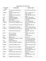
6.5.2
Response to time varying value of the characteristic quantity for dependent
time relays
The test waveform of the characteristic quantity is shown in Figure 8, which represents a
50 Hz or 60 Hz waveform modulated by a square wave so that the changes in magnitude of
the sine-wave occur at zero crossings.
Copyrighted material licensed to Electricity of Vietnam by Thomson Scientific, Inc. (www.techstreet.com). This copy downloaded on 2014-12-24 02:15:32 -0600 by authorized user Quach Lam hung.
No further reproduction or distribution is permitted.
60255-127 © IEC:2010
– 20 –
– 21 –
IEC
750/10
Figure 8 – Test waveform
The frequency of the modulating square-wave shall not be higher than 1/10 of the main
frequency, so that the transient behaviour of the relay does not affect the operate time.
The magnitudes G 1 and G 2 of the characteristic quantity are both above G S , the setting value
of the characteristic quantity. The magnitudes are selected so that the operate time of the
relay is high with respect to the period of the modulating square wave.
With the above conditions, the theoretical operate time T 0 is:
T0 =
2 ⋅ T1 ⋅ T2
T1 + T2
(4)
where
T 1 is the operate time for characteristic quantity equal to G 1;
T 2 is the operate time for characteristic quantity equal to G 2.
Recommended values for the time varying characteristic quantity are given in Table 5, where
the frequency of the modulating square-wave is 1/10 of the main frequency. With values of
Table 5, the measured operate time shall not differ from T 0 by more than 15 %.
Table 5 – Recommended values for the test
Curve
T
G1
G2
s
T1
T2
T0
s
s
s
Overvoltage
10
1,2 × G S
1,5 × G S
50
20
28,57
Undervoltage
10
0,5 × G S
0,2 × G S
20
12,5
15,39
NOTE
7
T is the time delay setting (see Equations (1) and (2)).
Documentation requirements
7.1
Type test report
The type test report for the functional elements described in this standard shall be in
accordance with IEC 60255-1. As a minimum the following aspects shall be recorded:
•
equipment under test: this includes details of the equipment / function under test as
well as specific details such as model number, firmware version shall be recorded as
applicable;
•
test equipment: equipment name, model number, calibration information;
Copyrighted material licensed to Electricity of Vietnam by Thomson Scientific, Inc. (www.techstreet.com). This copy downloaded on 2014-12-24 02:15:32 -0600 by authorized user Quach Lam hung.
No further reproduction or distribution is permitted.
60255-127 © IEC:2010
60255-127 © IEC:2010
•
functional block diagram showing the conceptual operation of the element including
interaction of all binary input and output signals with the function;
•
details of the input energising quantity and the type of measurement being used by the
function;
•
details of the available characteristic curves/operation for both operating and reset
states that have been implemented in the function, preferably by means of an
equation;
•
details of the behaviour of the function for voltages in excess of G D, and its value;
•
details of any specific algorithms that are implemented to improve the applicability of
this function to a real power system, and their performance claims. In the case of
generic algorithms that are used by more than one function, for example voltage
transformer supervision, it is sufficient to describe the operation of the algorithm once
within the user documentation but its effect on the operation of all functions that use it
shall be described;
•
test method and settings: these include details of the test procedure being used as
well as the settings that are applied to the equipment under test to facilitate the
testing. This may include settings other than those for the function being tested. This
permits repeat testing to be performed with confidence that the same test conditions
are being used;
•
test results: for every test case outlined in the test method and settings, the complete
sets of results are recorded as well as a reference to the particular test case. From
these results, accuracy claims are established;
•
test conclusions: based upon the recorded test results, all claims required by Clause
5 of this standard shall be clearly stated. Where appropriate, these claims are
compared with the performance specifications contained in this standard to allow
individual pass / fail decisions to be given, as well as an overall pass / fail decision for
the entire function.
7.2
Other user documentation
Not all users insist on viewing the complete type test documentation, but require a subset of
the information that it contains. For this purpose, as a minimum the following aspects shall be
recorded in generally available user documentation, although this may not be required in a
single document:
•
functional block diagram showing the conceptual operation of the element including
interaction of all binary input and output signals with the function;
•
details of the input energising quantity and the type of measurement being used by the
function;
•
details of the available characteristic curves/operation for both operating and reset
states that have been implemented in the function, preferably by means of an
equation;
•
details of the behaviour of the function for voltages in excess of G D, and its value;
details of any specific algorithms that are implemented to improve the applicability of
this function to a real power system, and their performance claims. In the case of
generic algorithms that are used by more than one function, for example voltage
transformer supervision, it is sufficient to describe the operation of the algorithm once
within the user documentation but its effect on the operation of all functions that use it
shall be described;
•
•
all claims required by Clause 5 of this standard shall be clearly stated.
Copyrighted material licensed to Electricity of Vietnam by Thomson Scientific, Inc. (www.techstreet.com). This copy downloaded on 2014-12-24 02:15:32 -0600 by authorized user Quach Lam hung.
No further reproduction or distribution is permitted.
– 22 –
– 23 –
Annex A
(informative)
Reset time determination for relays with trip output only
A.1
General
Measuring relays and protection equipment have different output configurations. For
equipment that has only a trip output the determination of a dependent reset time can be
achieved by many different methods. The following article describes an example of such a
test method.
A.2
Test method
The determination of the reset time for relays without an appropriate contact can be achieved
using the following method to determine a basic accuracy of the reset time. A voltage of twice
setting (or the maximum allowed if twice the voltage is more than the maximum allowed) is
applied to the relay for a pre-determined length of time such that the unit does not operate but
has reached 90 % of its trip value. The voltage is then reduced instantaneously to a predetermined value below setting for a fixed time. After this time has elapsed, the voltage is
instantaneously increased to twice setting value until the element trips. The trip time is
determined based on the value of the internal integrator. This is shown graphically in Figure
A.1. The test method is repeated with the applied voltage being reduced to a different value
on each occasion. This generates a range of trip times from which the reset times can be
extrapolated and with sufficient points a reset curve can be created.
IEC
751/10
Figure A.1 – Dependent reset time determination
Copyrighted material licensed to Electricity of Vietnam by Thomson Scientific, Inc. (www.techstreet.com). This copy downloaded on 2014-12-24 02:15:32 -0600 by authorized user Quach Lam hung.
No further reproduction or distribution is permitted.
60255-127 © IEC:2010