áp dụng LQR nghiên cứu xe hai bánh
Bạn đang xem bản rút gọn của tài liệu. Xem và tải ngay bản đầy đủ của tài liệu tại đây (1.19 MB, 10 trang )
Regulation of the two-wheeled inverted pendulum robot based on the settling time
and overshoot assignment method and LQR controller
Nam H. Nguyen1,∗, Xuan D. Tran1 , Long T. Pham1 , Trung D. Trinh1 , Khanh G. Tran1 , Phuoc D. Nguyen1
No. 1, Dai Co Viet Street, Hanoi, Vietnam
Abstract
In this paper, the novel overshoot and settling time assignment (OSA) technique in combination with a linear quadratic
regulator (LQR) is proposed to control a two-wheeled inverted pendulum robot (TWIPR) such that it is kept balanced
while following a path. The proposed TWIPR control system consists of two control loops. The inner loop has two
PI controllers for two DC motors’ currents, which are separately designed based on the OSA method. The outer loop
contains a LQR controller for the tilt angle, heading angle and position of the TWIPR. The OSA method is compared to
the existing methods such as the magnitude optimum (MO) and genetic algorithm (GA) methods. The proposed control
scheme is verified through simulations and practical tests with a TWIPR, and it is also compared to the MO-LQR and
GA-LQR strategies. The results show that the control strategy based on the OSA - LQR provides better performance
in terms of the TWIPR’s tilt angle and position.
Keywords: PID tuning, dc motor control, settling time, overshoot, two-wheeled inverted pendulum
1. Introduction
5
10
15
20
25
TWIPRs are widely studied and applied in practice
and literature [1, 2, 3]. The input to the TWIPR is usually
torques produced by two DC motors. These torques are 30
directly proportional to currents caused by the DC motors.
Thus, the current controllers are crucial to the TWIPR.
However, most of the works [4, 5, 6, 7, 8, 9, 10, 11, 12, 13,
14, 15, 16, 17, 18, 19] about TWIPR have not addressed
the problem of current or torque control. In addition, the 35
voltages, applied to the DC motors, are considered as the
input to the TWIPR in stead of torques.
In [4], an adaptive backstepping controller combined
with two PD controllers is proposed for an electric scooter.
The input to the vehicle are torques produced by two DC 40
motors, but there is neither torque nor current controller
designed. The proposed control scheme is tested through
both simulation and experiment. Sliding mode controllers
and model based friction compensation are proposed in [5]
for a TWIPR. This approach is also verified via simula- 45
tion and real test. However, the torque/current control
problem is also not dealt with. In [6], a nonlinear state
transformation based controller is proposed. Then, the
regulator is tested through simulation. A combination of
two PD controllers and a time-delayed controller [7] for 50
fast movement of TWMR is proposed, in which the first
∗ Corresponding
author
Email address: (Nam H.
Nguyen)
1 Department of Automatic Control, School of Electrical Engineering, Hanoi University of Science and Technology
Preprint submitted to Elsevier
55
PD controller is designed for the pitch angle, the other
PD controller is applied for the orientation, and the timedelayed controller is synthesised for the position. Practical
test is carried out to prove the proposed method. In [8], the
proposed control scheme consists of local controller and a
global planner for the TWIPR based personal transportation vehicle, in which the local controller contains three
PID controllers for the pitch angle, the yaw angle and the
position. The vehicle is tested with different passengers.
Three fuzzy logic inference system based controllers are designed for the TWIPR in [9]. The control system is verified
through simulation and experimental test. In [10], an indirect adaptive fuzzy controller based on trajectory planner
for the TWIPR is given. The control strategy is verified
through simulation. In [11], adaptive sliding mode control in combination with direct fuzzy control is applied for
balancing and trajectory tracking of the TWIPR. A statedependent nonlinear model based LQR is investigated in
[12]. It is compared to the classical LQR controller via
simulation and real test, and its performance is better in
term of high yaw rate. In [13], a backstepping controller
is designed for trajectory tracking and sliding mode controllers are applied for the TWIPR’s velocities and pitch
angle. Four interval type 2 fuzzy logic inference system
based controllers [14] are designed with usage of TakagiSugeno model for the TWIPR such that the vehicle is able
to reach the desired point and orientation while its balancing is kept. The proposed control strategy is verified
through experiments. In [15], a passivity based controller
with usage of two rule Takagi-Sugeno fuzzy model is proposed for the TWIPR. This control scheme is tested via
February 27, 2019
60
65
70
☎
✖ ✘✓ ✗✘✔
simulation. A novel TWIPR with four-bar parallel mechanism is developed in [16], in which the horizontal posture
is guaranteed. Simulation and practical test are carried
out. In [17], a model predictive controller for the trajectory tracking of TWIPR is proposed, and verified through
numerical simulations. A trajectory planning and tracking control for obstacle avoidance of the TWIPR is given
in [18]. A control of cooperative double-wheel inverted
pendulum robots based on Udwadia-control approach is
recently proposed in [19] for the first time.
In this work, the novel overshoot and settling time assigment method [20] is applied to design PI controllers for
the TWIPR for the first time, and it is compared with the
other methods. Then, these controllers are combined with
an LQR controller to keep the TWIPR balanced and able
to move straight forwad, make an U-turn and even take
a load, since the LQR controller is the simplest control
strategy among the other advanced control methods.
☎
✖ ✕✓ ✗✕✔
☎✆
✝
✁
85
✄
☎✎
✝
☛
☎✟
✝
☞✡
☎✌
✞
☎✌
✞
✒
✄
☎✌
✝
✑
[I3 + 2K + md2 /2 + Jd2 /(2r2 ) − (I3 − I1 − M l2 )sin2 (θ)]ψ¨
˙
+ [M lx˙ − 2(I3 − I1 − M l2 )]ψsin(θ)
˙ 2 /(2r2 ) = (iR − iL )Km d/(2r)
+ C ψd
(3)
Let define state variables and inputs as
x = [x1
= [x
2.1. Mathematical Model
95
✂
✡
✠
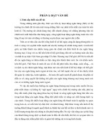
Figure 1: Schematic diagram of a TWIPR
The next section presents the mathematical model and
the proposed control system for the TWIPR. In section 3,
the OSA based PI controllers are designed for two DC
motors’ currents of the TWIPR and they are compared
to the MO and GA methods through simulations and experiments. In section 4, a LQR controller is designed to
maintain that the TWIPR is vertically stable and it able to
reach desired position and orientation. Some simulations
and practical tests for the TWIPR are given in section 5.
The final section provides a summary and future works.
2. Two-Wheeled Inverted Pendulum Robot
90
☎✎
✞
✍✎✏
75
80
☎✆
✞
☎
✖ ✙✓ ✗✙✔
x2
θ
x4 x5 x6 ]T
˙T
x˙ θ˙ ψ]
x3
ψ
(4)
and
In this work, the mathematical model of TWIPR in [21]
is used for simulation and controller design. The schematic
diagram of a TWIPR is shown in Fig. 1. The notations
and parameters of the TWIPR are shown in Tab. 1,where
J = mr2 /2, K = mr2 /4, I1 = I3 = M d2 /2, I2 = M l2 /2.
The inputs of the model [21] are torques produced by motors, but in this work, the two motors’ currents are used
instead of torques as the inputs to the TWIPR. Thus, the
motion equations of the TWIPR are represented as in Eq.
1, 2 and 3.
u = [u1
u2 ]T = [iL
iR ]T
(5)
respectively. Then,
x˙ = f (x, u)
(6)
in which x˙ 1 = x4 , x˙ 2 = x5 , x˙ 3 = x6 , x˙ 4 = f4 (x, u),
2
x˙ 5 = f5 (x, u) and x˙ 6 = f6 (x, u) where f4 (x, u) = Ω1 +Ω
,
Ω
Ω3 +Ω4
Ω5
f5 (x, u) = Ω , f4 (x, u) = Ω6 with
Ω1 =r2 (M l2 + I2 ) Km (u1 + u2 )/r + 2C(x5 − x4 /r)/r
+ M lsin(x2 )(x25 + x26 ) ,
2J
)¨
x − M l(ψ˙ 2 + θ˙2 )sin(θ) + M lcos(θ)θ¨
r2
(1)
2 x˙
Km
˙
+ ( − θ) =
(iL + iR )
C r
r
(M + 2m +
Ω2 =M lr2 cos(x2 ) − cos(x2 )sin(x2 )(M l2 + I1 − I3 )x26
+ Km (u1 + u2 ) + 2C(x5 − x4 /r) − M glsin(x2 ) ,
M lcos(θ)¨
x − (M l2 + I2 )θ¨ + (I3 − I1 − M l2 )ψ˙ 2 sin(θ)cos(θ)
x˙
˙ = −Km (iL + iR )
− M lgsin(θ) − 2C( − θ)
r
(2)
Ω3 = 2J + (M + 2m)r2 cos(x2 )sin(x2 )(M l2 + I1 − I3 )x26
− Km (u1 + u2 ) − 2C(x5 − x4 /r) + M glsin(x2 ) ,
Ω4 = − M lr2 cos(x2 ) Km (u1 + u2 )/r + 2C(x5 − x4 /r)/r
+ M lsin(x2 )(x25 + x26 ),
2
Table 1: TWIP’s notations and parameters
Notation
x
θ
ψ
d
l
r
M
m
J
K
Km
iL , iR
τL , τR
C
I1 , I1 , I1
Definition
Position of the TWIPR
Pitch angle of the pendulum body
Yaw angle of the TWIPR
Distance from the left to right wheels
Length from the center of the pendulum
to the wheel axis
Radius of wheels
Mass of the pendulum (without wheels)
Mass of left (right) wheel
Mass moment of inertia (MOI) of the wheel
with respect to (w. r. t.) the wheel axis
MOI of the wheel w. r. t. the vertical axis
the motor torque constant
the left, right armature current
motor’s left (right) torque
coefficient of viscous friction on wheel axis
MOI of the pendulumn w. r. t. the frame
at the center of the pendulumn
Figure 2: Block diagram of the TWIPR control system
Ω5 = − 2r2 Km d(u1 − u2 )/(2r) + x6 sin(x2 ) M lx4
+ 2x5 cos(x2 )(M l2 + I1 − I3 ) + Cd2 x6 /(2r2 ) ,
Figure 3: Front view of a TWIPR under control in laboratory
Ω6 = 2I3 + 4K + md2 + 2(I1 − I3 + M l2 )sin2 (x2 ) r2
+ Jd2 ,
and
Ω =(M lr)2 (1 − cos2 (x2 )) + 2I2 J + 2JM l2
+ (I2 M + 2I2 m + 2M ml2 )r2 .
100
The motion equations 1, 2 and 3 are used to design the
LQR controller in Section 4. In the next section, PID
controllers are designed to stabilize two motors’ currents,
which create desired inputs to the TWIPR.
2.2. TWIPR Control System
105
110
The block diagram of the proposed control strategy is
shown in Fig. 2. It contains three control loops, in which
the first two inner loops consist of two PI controllers and
the third loop has a LQR controller. Pictures of the controlled TWIPR in the laboratory is shown in Fig. 3 and
Fig. 4.
Figure 4: Side view of a TWIPR under control in laboratory
The TWIPR control system mainly consists of two DC
motors, two current sensors based on the INA219, two incremental encoders, two wheels, pendulum body, the MPU115 2.2.1. DC Motor
Each DC motor has a gear train with a gear ratio of n =
6050 based tilt angle sensor, three batteries and the Dis1/34.
This means that the wheel, attached to the output
covery kit with STM32F411VE MCU (powered by a 9V
shaft
of
the gear train, rotates n times for each revolution
and 200mAh battery).
3
125
130
of the motor shaft. These two motors are powered by three
3.7V and 4000mAh batteries (UltraFire).
2.2.2. Incremental Encoder
135
An encoder is also attached to each DC motor’s rotor
shaft. The encoder has two channels and each channel has
N = 13 pulses per revolution of the motor. This incremental encoder are used with the highest resolution, so there
are 4N/n = 1768 pulses per revolution of the wheel. It
is applied to measure both the angle and velocity of the
wheel, then from these measurements, the position, head-140
ing angle, velocity and vertical speed of the TWMR are
estimated.
2.2.3. Kalman Filter
In this subsection, the Kalman filter [22] is applied to
estimate the tilt angle of the pendulum. Let ζk be the145
gyroscope signal from the MPU 6050 at discrete point k
in time, ζkbias be the deviation of the ζk , and ∆T be the
sampling time. Then, the tilt angle of the pendulum can
be approximately calculated as
θk = θk−1 + (ζk − ζkbias )∆T
Define state variables as zk = [θk
space model is
• Step 1: Calculate the Kalman gain using Eq. 10
• Step 2: Update estimate with measurement using
Eq. 9
• Step 3: Determine error covariance for updated estimate using Eq. 11
• Step 4: Project ahead using Eq. 12, then go back
the first step
This algorithm will be used to estimate the tilt angle of
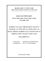
the pendulum based on the MPU 6050 sensor. In Fig. 5,
an example of the measured tilt angle is shown, where the
black curve is the angle with Kalman filter and the blue
curve is the angle without filter.
5
(7)
yk = Cθ zk + vk
Without Kalman
With Kalman
0
ζkbias ]T . Then, the state
zk = Aθ zk−1 + Bθ uk + wk
θ
Thus, the Kalman filter can be implemented as the following steps:
Start with a prior estimate z0 and its error covariance matrix P0− .
-5
-10
Degrees
120
(8)
-15
-20
where
1
Aθ =
0
Bθ =
−∆T
,
1
-25
-30
∆T
,
0
-35
0
Cθ = [1 0], uk = ζk , wk is the input white noise, and vk is
the measurement white noise. Denote covariance matrices
for wk and vk as Qk and Rk , respectively.
Let zˆk− be the prior estimate, e−
ˆk− be the estik = zk − z
mation error, and the respective error covariance matrix
− T
θ
Pk− = E[e−
k (ek ) ]. Then, the measurement yk will be
used to improve the prior estimate as follows
zˆk = zˆk− + Kk (θ yk − Cθ zˆk− )
−
Pk+1
= Aθ Pk ATθ + Qk
10
12
14
(9)150 3.1. Current Model Identification
In this section, the transfer function for the current of
DC motors will be built based on the unit step response.
The electrical equation [23] for a DC motor is described as
(10)
di
(13)
dt
where u is the motor armature voltage, R is armature
coil resistance, L is armature coil inductance, i is the armature current, e = Ke ω is the back electromotive-force
voltage, ω is the motor angular speed, τ = Km i is the
motor torque, Ke is an electrical constant, and Km is the
motor torque constant.
u = e + Ri + L
(11)
At time k + 1,
−
zˆk+1
= Aθ zˆk + Bθ uk
6
8
Seconds
2.2.4. Stability Analysis
3. Current Controller Design
The covariance matrix with respective to the optimal estimate can be calculated as
Pk = (I − Kk Cθ )Pk−
4
Figure 5: Measured pitch angles with and without Kalman filter
where Kk is a Kalman gain or blending factor and zˆk is
an updated estimate. The Kalman gain is computed as
Kk = Pk− CθT (Cθ Pk− CθT + Rk )−1
2
(12)
4
Thus, the transfer function for the current of the motor is
Gi (s) =
I(s)
1
=
U (s)
R + Ls
(14)
k
Ts + 1
(15)
or
Gi (s) =
155
are determined as
kP = −
0.13919
1.23 ∗ 10−4 s + 1
(19)
TI = T1 + T2 ,
(20)
T1 T2
T1 + T2
(21)
and
where k = 1/R and T = L/R.
To determine these parameters, a unit-step response based
approach is applied. An voltage of 6V is supplied to the
motor, then the motor’s current is measured as shown in
Fig. 6. Based on this measured current, the current transfer function is obtained as follows
Gi (s) =
a
(T1 + T2 )ln 100
,
kTa%
TD =
Remark 1. With this OSA method, one can design a PID
controller such that the settling time is smaller than Ta% ,
where 0 < a ≤ 100. This proposed method also guarantees
that the overshoot is zero.
(16)170 Remark 2. For the system 15, T = 0 so the parameters
2
a
T ln 100
, TI = T , and TD =
of the PID controller is kP = − kTa%
0.
1
For the plant 16, the desired settling time is chosen as
Ta% = 1 ms. Thus, the parameters of the PI controller are
computed as kP = 3.4563 and TI = 1.23 ∗ 10−4 from Eq.
19 and Eq. 21 with T2 = 0.
As the magnitude optimum method [24] is applied for the
current object, the parameter of the I controller
0.9
0.8
Model's output
Motor's current
Current (A)
0.7
0.6
0.5
0.4
Rmo (s) =
0.3
1
Ti s
(22)
0.2
is calculated as
0.1
Ti = 2kT = 3.4232 ∗ 10−5
0
0
0.001
0.002
0.003
0.004
0.005
0.006
0.007
0.008
0.009
0.01
(23)
Time (Seconds)
The GA method [25] is also utilized to determine the current controller for the plant 16 with the usage of following
objective function
Figure 6: Motor’s current and model’s current
From the identified model (16), the current controllers
are designed with usage of different methods in the next
section.
160
3.2. Current Controller Design based on the OSA Method
165
In this section, the novel assignment method (OSA)
in [20] will be applied to design a PI controller for the
DC motor’s current and compared to the other methods
such as GA and MO methods via simulations and practical
experiments.
tf inal
k
(T1 s + 1)(T2 s + 1)
The GA based PI controller is obtained as follows
Rga (s) = 0.064 +
175
(17)
180
and a desired settling time Ta% , then the parameters of the
PID controller with transfer function
Rp (s) = kP (1 +
1
s + TD s)
TI
(24)
0
Lemma 1. [20] Given a plant with transfer function of
second-order system
G(s) =
t|e(t)|dt → min
J=
(18)185
5
9936
s
(25)
These PID controllers are utilized to control the motor’s
current. Both simulation and practical test are carried out
to compare the OSA method with the other methods as
shown in Fig. 7, 8 and 9. In Fig. 7, the controlled current
is plotted via simulation. It can be seen that the OSA
method provides shorter settling time than the GA and
MO methods. It also produces a zero overshoot as the GA
method. The practical result is shown in Fig. 8, where the
OSA scheme produces the best performance in comparison with the GA and MO methods. This will improve the
control performance of the TWIPR. Fig. 9 shows the actual control signal (the applied voltage to the DC motor)
produced by the different controllers. The overshoot and
settling time given by the controllers through both simulation and real test are compared in Tab. 2. For the overall,
6
0.7
0.6
Set Point
Proposed Method
GA
Magnitude Optimum
0.4
4
Voltage (V)
0.5
Current(A)
Proposed Method
Magnitude Optimum
GA
5
0.3
3
2
0.2
1
0.1
0
0
0
0.005
0.01
0.015
0.02
0.025
0.03
0
0.005
0.01
0.015
Time(s)
Figure 7: Simulation of the controlled current using different controllers
0.7
Current (A)
0.6
Set Point
Proposed Method
GA
Magnitude Optimum
0.3
where
0.2
0.1
0
A=
-0.1
0
0.005
0.01
0.015
0.03
[∗ 0 ∗ 0 0 0]T , where ∗ are any values of x1 and
x3 , which are the desired position and heading angle of
the TWIPR. Without loss of generality, it is assumed that
∗ is zero, this means xe = 0. Thus, a linear model of the
system 6 around the equillibrium point xe can be obtained
as follows
x˙ = Ax + Bu
(26)
0.8
0.4
0.025
Figure 9: Practical control signal using different controllers
0.9
0.5
0.02
Time (s)
0.02
0.025
0.03
∂f
∂x
x=xe
Time (s)
0
0
0
=
0
0
0
0
0
0
a42
a52
0
0 1
0 0
0 0
0 a44
0 a54
0 0
0
1
0
a45
a55
0
0
0
1
0
0
a66
(27)
Figure 8: Practical regulated current using different controllers
190
the OSA method is better than the MO and GA methods
in terms of both overshoot and settling time. The OSA
based PI controller will be applied to control the two motors’ currents of the TWIPR. In the next section, a LQR
controller combined with the proposed PI controller is designed to keep the TWIPR balanced and movable with
desired trajectories.
B=
OSA
MO
GA
T2% (ms)
Simulation Test
1
1.1
1.04
3
2.42
2.5
Overshoot
Simulation
0
4.32
0
(%)
Test
1.36
29.92
1
x=xe
0
0
0
b42
b52
b62
(28)
2
−(M gl)2 g
, a44 = −2C((M l Λ+I2 )+M lr) , a45 =
Λ
2
2
2Cr(M l2 +I2 )+2CM lr 2
, a52 = M gl(2J+MΛr +2mr ) , a54 =
Λ
2
2
2CM l+2C(2J+M r 2 +2mr 2 )/r
)+2CM lr
, a55 = 2C(2J+M r +2mr
,
Λ
−Λ
2
2
Km r[(M l +I2 )+M lr]
−Cd
a66 = 2Jd2 +(2I3 +4K+d2 m)r2 , b41 = b42 =
,
Λ
−Km (2J+M r 2 +2mr 2 +M lr)
b51 = b52 =
, b61 = −b62 =
Λ
−Km dr
2
2
Jd2 +(2I3 +4K+d2 m)r 2 , and Λ = 2I2 J + 2JM l + I2 M r +
2
2
2
2I2 mr + 2M l mr .
with a42 =
Table 2: Comparison of methods through simulation and real test
Method
∂f
∂u
0
0
0
=
b41
b51
b61
200
4.2. LQR Controller
195
From the linear model 26, a LQR controller [26] is designed such that the following cost function is minimum.
4. LQR Controller Design
4.1. Linearized Model of the TWIPR
Let xe be an equilibrium point of the system 6, then
xe is the solution to the equation f (x, 0) = 0. Thus, xe =
F =
6
1
2
∞
(xT Qc x + uT Rc u)dt → min
0
(29)
5. Simulation and Practical Test
KLQR = Rc−1 B T Pc
(30)220
and Pc is the solution to the Riccati equation
Pc BRc−1 B T Pc − Pc A − AT Pc = Qc .
(31)
In this paper, the values of the TWIPR’s parameters are
determined from a real TWIPR as follows M = 0.5kg,
m = 0.04kg, l = 0.08m, d = 0.16m, r = 0.033m, g =225
9.81m/s2 , C = 0.005, Km = 0.41202N m/A. Thus, the
system matrices
0
0
0
1
0
0
0
0
0
0
1
0
0
0
0
0
0
1
(32)
A=
1.35
0
0 −11.41 0 −40.85
0 176.81 0 403.48 −13.31
0
0
0
0
0
0
−8.17
In this section, the propsed control scheme based on
the OSA method and LQR controller is verified for the
TWIPR through simulation and experiments. Then, it is
compared to the other methods. The TWIPR is controlled
to move from the initial point to the end point along a line,
where the distance between these two points is 1 meter.
5.1. The proposed control strategy
The simulation results are shown in Fig. 10, 11 and
12 whereas the real-time run results are shown in Fig. 13,
14 and 15. The left motor’s measured current and right
motor’s measured current are shown in Fig. 16 and 17.
0.4
0.3
(rad)
where Qc is a symmetric positive definite matrix and Rc
is a symmetric nonnegative definite matrix.
The controller, which satisfies the cost function 29, is u =
−KLQR x, where
0.2
0.1
0
0
0
0
0
0
B=
55.53
55.53
−548.60 −548.60
−138.92 138.92
The matrices of the cost function are chosen as
4 0 0
0
0
0
0 3 0
0
0
0
0 0 20 0
0
0
Qc =
0
0
0 0 0 3.5
0 0 0
0 0.001 0
0 0 0
0
0
0.9
0
-0.1
0
(33)
2
4
6
8
10
12
14
16
18
20
Time(s)
Figure 10: The tilt angle of the pendulumn through simulation
10-15
6
4
(34)
(rad)
and
2
0
and
-2
1 0
.
(35)
0 1
From Eq. 30 and Eq. 31, the gain matrix of the LQR
controller is obtained as
Rc =
-4
0
210
6
8
10
12
14
16
18
20
Figure 11: The heading angle of the TWIPR through simulation
−2.147
−2.147
−0.33 −0.659
−0.33 0.659
(36)
The output of the LQR controller will be the setpoints
for the current controllers, which are belong to the inner
control loop.
1
0.8
0.6
x (m)
205
4
Time(s)
KLQR =
−1.414 −3.098 −3.162
−1.414 −3.098 3.162
2
Remark 3. Since the input to the LQR controller consists
˙ and (ψ; ψ),
˙ the LQR
of state variable pairs (x; x),
˙ (θ; θ)
output is similar to the sum of the three PD controllers’
output as in works [4, 7, 8], in which each state variable
pair is the input to one PD controller.
0.4
0.2
0
-0.2
0
2
4
6
8
10
12
14
16
18
20
Time(s)
215
Remark 4. The LQR controller in [12] is also compared
to the state-dependent LQR controller when the high yaw
rate is considered.
Figure 12: The position of the TWIPR through simulation
7
2
0.6
1.5
0.5
1
IR (A)
0.4
(rad)
0.3
0.5
0
0.2
-0.5
0.1
-1
0
-1.5
0
2
4
6
8
10
12
14
16
18
20
Time(s)
-0.1
0
2
4
6
8
10
12
14
16
18
20
Time(s)
Figure 17: Right motor’s real current
Figure 13: The real tilt angle of the pendulumn
10-3
5
230
(rad)
0
-5
-10
235
-15
From these figures, one can see that the real-time results look like the simulation results, this implies that a
good model of the TWIPR is built and the controllers
works well. The proposed control strategy produces good
performance such as the pitch angle lies within the range
[−3 3] (deg), the TWIPR reaches the destination at 1
(m) after 3.5 (seconds) following a straight line because the
yaw angle is approximately within the range [−0.3 0.3]
(deg).
-20
0
2
4
6
8
10
12
14
16
18
20
5.2. Comparisons
Time(s)
Figure 14: The real heading angle of the TWIPR
240
1.2
1
x (m)
0.8
0.6
245
0.4
The proposed control scheme based on the OSA-LQR
method is compared to the MO-LQR and GA-LQR methods through practical tests. The desired trajectory is a
straight line with a length of 1 meter. Fig. 18 shows the
positions of the TWIPR with different methods, where the
blue curve, the black curve and the red curve are positions
of the TWIPR provided by the OSA-LQR method, the
MO-LQR method and the GA-LQR method, respectively.
The comparison of the pitch and yaw angles of the
0.2
1.2
0
-0.2
0
2
4
6
8
10
12
14
16
18
1
20
Time(s)
0.8
OSA -LQR
MO - LQR
GA - LQR
x (m)
Figure 15: The real position of the TWIPR
1
0.6
0.4
0.5
IL (A)
0.2
0
0
-0.5
-0.2
0
-1
2
4
6
8
10
Time(s)
-1.5
0
2
4
6
8
10
12
14
16
18
20
Figure 18: The position of the TWIPR with different methods
Time(s)
Figure 16: Left motor’s real current
TWIPR with different methods are shown in Fig. 19
and Fig. 20, respectively. Since the yaw angles are very
small for all methods, the TWIPR moves nearly along the
8
265
0.8
OSA - LQR
MO - LQR
GA - LQR
0.6
(rad)
0.4
270
0.2
the others. Then, the proposed control system is verified
and compared to the other methods through simulations
and practical tests. The obtained results show that the
TWIPR is kept balanced and able to reach the desired
position and direction, and the proposed controller produces better performance than the others. Future works
will focus on the combination of the OSA method with
other advanced control methods for the TWIPR and other
robots.
0
7. Acknowledgments
-0.2
275
-0.4
0
2
4
6
8
10
Time (s)
Figure 19: The pitch angle of the TWIPR with different methods
250
References
straght line with a distance of 1 meter. The OSA-LQR280
based TWIPR moves more smoothly from the start point
to the end point with smaller pitch angle and less oscillation than the other methods. Hence, the proposed con285
troller provides better performance than the others.
10-3
5
290
OSA - LQR
MO - LQR
GA - LQR
0
(rad)
295
-5
-10
300
-15
305
-20
0
2
4
6
8
10
Time (s)
Figure 20: The yaw angle of the TWIPR with different methods
310
255
Remark 5. The proposed control scheme is also tested
with different loads and inclined surfaces. The practical315
results prove that the TWIPR is kept balanced and movable. However, they are skipped to show here.
260
6. Conclusions
This research is funded by the Hanoi University of
Science and Technology (HUST) under project number
T2017-TT-004.
320
In this work, the TWIPR control system based on the
OSA-LQR controller is proposed. First, the OSA method
is compared to the MO and GA methods through the325
DC motor’s current. It produces better performance than
9
[1] Zhijun L., Chenguang Y., and Liping F. (2013). Advanced Control of Wheeled Inverted Pendulum Systems, Springer.
[2] Ronald P. M. C., Karl A. S., and Roger H. (2013). Review of
modelling and control of two-wheeled robots. Annual Reviews
in Control, 37 (1), pp. 89-103.
[3] Khanh G. T., Phuoc D. N., and Nam H. N. (2017). Advanced
control methods for two-wheeled mobile robots. The proceedings of International Conference on System Science and Engineering. Ho Chi Minh, Vietnam, Sep. 2017.
[4] Son. N. N. and Anh. P. H. H. (2014). Adaptive Backstepping
Self-balancing Control of a Two-wheel Electric Scooter, Int.
Jour. Advan. Robo. Syst., 11 (10), pp. 1–11
[5] Fuquan D., Xueshan G., Shigong J., Wenzeng G., and Yubai L.
(2015). A two-wheeled inverted pendulum robot with friction
compensation. Mechatronics 30, pp. 116–125.
[6] R. M. Brisilla and V. Sankaranarayanan (2015). Nonlinear control of mobile inverted pendulum. Robotics and Autonomous
Systems 70, pp. 145–155.
[7] Sung T. C. and Seul J. (2015) Combining Two Control Techniques for the Fast Movement of a Two-Wheel Mobile Robot.
Inter. Jour. Human. Robot, 12 (2), pp. 1–14
[8] Kim H. W. and Jung S. (2016). Control of a two-wheel robotic
vehicle for personal transportation. Robotica, 34 (5), pp. 1186–
1208.
[9] Akos O., Ervin B., Istvan K., Janos F. and Peter O. A. (2016).
Fuzzy Control of a Two-Wheeled Mobile Pendulum System.
Proceedings of the 11th IEEE Int. Symp. Appl. Comp. Intel.
Infor., Romania.
[10] Ming Y., Cong A., Yu D. and Jianzhong S. (2016). Indirect adaptive fuzzy control for a nonholonomic/underactuated
wheeled inverted pendulum vehicle based on a data-driven trajectory planner, Fuzzy Sets and Systems 290, pp. 158–177.
[11] Ming Y., Shuang W. and Jian-Zhong S. (2016). Simultaneous
balancing and trajectory tracking control for two-wheeled inverted pendulum vehicles: A composite control approach. Neurocomputing 191, pp.44–54.
[12] Sangtae K. and SangJoo K. (2017). Nonlinear Optimal Control Design for Underactuated Two-Wheeled Inverted Pendulum Mobile Platform. IEEE/ASME Transactions on Mechatronics, 22 (6), pp. 2803 - 2808.
[13] Nasim EsmaeiliAlireza A. and Hossein K. (2017). Balancing and
Trajectory Tracking of Two-Wheeled Mobile Robot Using Backstepping Sliding Mode Control: Design and Experiments. Journal of Intelligent and Robotic Systems, 83 (3), pp. 601–613.
[14] Jian H., MyongHyok R., Dongrui W., and Songhyok R. (2018).
Interval Type-2 Fuzzy Logic Modeling and Control of a Mobile
Two-Wheeled Inverted Pendulum. IEEE Transactions on Fuzzy
Systems 26 (4), pp. 2030–2038.
330
335
340
345
350
355
360
365
[15] Rongjun L., Junfeng W., and Dan W. (2018). Sampled-data
Fuzzy Control of Two-wheel Inverted Pendulums Based on Passivity Theory. International Journal of Control, Automation and
Systems. 16 (5), pp. 2538-2548.
[16] Seonghee J. and Taisei H. (2018). Development of a wheeled inverted pendulum mobile platform with a four-bar parallel mechanism. Advanced Robotics. 32 (4), pp. 1–11.
[17] Ming Y., Cong A., and Jian-Zhong S. (2018). An Efficient Model
Predictive Control for Trajectory Tracking of Wheeled Inverted
Pendulum Vehicles with Various Physical Constraints. International Journal of Control, Automation and Systems, 16 (1), pp.
265–274.
[18] Yigao N., Ming Y., Lu Y. and Xiaoqiang H. (2018). A trajectory
planning and tracking control approach for obstacle avoidance
of wheeled inverted pendulum vehicles. International Journal of
Control, />[19] Chunsheng H., Kang H., Xiaolong C., Yiran Z. and Han Z.
(2018). Transportation control of cooperative double-wheel inverted pendulum robots adopting Udwadia-control approach.
Nonlinear Dynamics, 91 (4), pp. 2789–2802.
[20] Nam. H. N. and Phuoc D. N. (2018). Overshoot and settling
time assignment with pid for first-order and second-order systems. IET Control Theory and Applications, 12 (17), pp. 2407–
2416.
[21] Sangtae K. and SangJoo K. (2015). Dynamic Modeling of a
Two-wheeled Inverted Pendulum Balancing Mobile Robot. International Journal of Control, Automation, and Systems, 13
(4) pp. 926–933.
[22] Robert G. B. and Patrick Y. C. H. (2012). Introduction to Random Signals and Applied Kalman Filtering with Matlab Exercises, Fourth Edition, John Wiley and Sons, Inc.
[23] Jinzhu P. and Rickey D. (2011). Identification andadaptive neural network control of a DC motor system with dead-zone characteristics. ISA Transactions, 50, pp. 588–598.
[24] Jeffrey W. U. and Mohammed S. (1990). Magnitude and symmetric optimum criterion for the design of linear control systems: What is it and how does it compare with the others?.
IEEE Trans. Indus. Appl., 26 (3), pp. 489–497.
[25] Neenu T. and Poongodi P. (2009). Position Control of DC Motor
Using Genetic Algorithm Based PID Controller. Proc. Worl.
Cong. Engineering, London UK, pp. 1–5
[26] Brian D. O. A. and John B. M. (1989). Optimal Control: Linear
Quadratic Methods. Prentice-Hall International, Inc.
10