SỬ DỤNG PHẦN MỀM QUEST ĐỂ PHÂN TÍCH CÂU
Bạn đang xem bản rút gọn của tài liệu. Xem và tải ngay bản đầy đủ của tài liệu tại đây (2.9 MB, 25 trang )
Performance Evaluation and Design Trade-Offs for Wireless
Network-on-Chip Architectures
KEVIN CHANG and SUJAY DEB, Washington State University
AMLAN GANGULY, Rochester Institute of Technology
XINMIN YU, SUMAN PRASAD SAH, PARTHA PRATIM PANDE, BENJAMIN BELZER,
and DEUKHYOUN HEO, Washington State University
Massive levels of integration are making modern multicore chips all pervasive in several domains. High
performance, robustness, and energy-efficiency are crucial for the widespread adoption of such platforms.
Networks-on-Chip (NoCs) have emerged as communication backbones to enable a high degree of integration
in multicore Systems-on-Chip (SoCs). Despite their advantages, an important performance limitation in
traditional NoCs arises from planar metal interconnect-based multihop links with high latency and power
consumption. This limitation can be addressed by drawing inspiration from the evolution of natural complex
networks, which offer great performance-cost trade-offs. Analogous with many natural complex systems,
future multicore chips are expected to be hierarchical and heterogeneous in nature as well. In this article
we undertake a detailed performance evaluation for hierarchical small-world NoC architectures where
the long-range communications links are established through the millimeter-wave wireless communication
channels. Through architecture-space exploration in conjunction with novel power-efficient on-chip wireless
link design, we demonstrate that it is possible to improve performance of conventional NoC architectures
significantly without incurring high area overhead.
Categories and Subject Descriptors: C.2.1 [Computer-Communication Networks]: Network Architecture
and Design
General Terms: Design, Performance
Additional Key Words and Phrases: Multicore, NoC, small-world, wireless links
ACM Reference Format:
Chang, K., Deb, S., Ganguly, A., Yu, X., Sah, S. P., Pande, P. P., Belzer, B., and Heo, D. 2012. Performance
evaluation and design trade-offs for wireless network-on-chip architectures. ACM J. Emerg. Technol. Comput.
Syst. 8, 3, Article 23 (August 2012), 25 pages.
DOI = 10.1145/2287696.2287706 />
1. INTRODUCTION
Power density limitations will continue to drive an increase in the number of cores in
modern electronic chips. While traditional cluster computers are more constrained by
power and cooling costs for solving extreme-scale (or exascale) problems, the continuing
progress and integration levels in silicon technologies make possible complete end-user
systems on a single chip. This massive level of integration makes modern multicore
This article is an extended version of the conference paper that appeared in ASAP [Deb et al. 2010].
This work was supported by the National Science Foundation under CAREER grant CCF-0845504 and in
part by the National Science Foundation under CAREER grant ECCS-0845849.
Authors’ addresses: K. Chang and S. Deb, Washington State University; A. Ganguly, Rochester Institute of
Technology; X. Yu, S. P. Sah, P. P. Pande (corresponding author), B. Belzer, and D. Heo, Washington State
University; email:
Permission to make digital or hard copies of part or all of this work for personal or classroom use is granted
without fee provided that copies are not made or distributed for profit or commercial advantage and that
copies show this notice on the first page or initial screen of a display along with the full citation. Copyrights for
components of this work owned by others than ACM must be honored. Abstracting with credit is permitted.
To copy otherwise, to republish, to post on servers, to redistribute to lists, or to use any component of this
work in other works requires prior specific permission and/or a fee. Permissions may be requested from
Publications Dept., ACM, Inc., 2 Penn Plaza, Suite 701, New York, NY 10121-0701 USA, fax +1 (212)
869-0481, or
c 2012 ACM 1550-4832/2012/08-ART23 $15.00
DOI 10.1145/2287696.2287706 />ACM Journal on Emerging Technologies in Computing Systems, Vol. 8, No. 3, Article 23, Pub. date: August 2012.
23
23:2
K. Chang et al.
chips all pervasive in domains ranging from climate forecasting and astronomical data
analysis, to consumer electronics, and biological applications [Pande et al. 2011]. According to the U.S. Environmental Protection Agency (EPA), one of the promising ways
to reduce energy dissipation of data centers is to design energy-efficient multicore chips
[EPA 2007]. With increasing number of cores, high performance, robustness, and low
power are crucial for the widespread adoption of such platforms. Achieving all of these
goals cannot simply be attained by traditional paradigms and we are forced to rethink
the basis of designing such systems, in particular the overall interconnect architecture. Network-on-Chip (NoC) is accepted as the preferable communication backbone
for multicore Systems-on-Chip (SoCs). The achievable performance gain of a traditional NoC is limited by planar metal interconnect-based multihop links, where the
data transfer between two far apart blocks causes high latency and power consumption. With a further increase in the number of cores on a chip, this problem will be
significantly aggravated. On the other hand, natural complex networks are known to
provide excellent trade-offs between latency and power with limited resources [Petermann et al. 2006]. Thus, drawing inspiration from such networks could enable radically
new designs. The human brain, colonies of microbes, and many other natural complex
networks have the so-called small-world property, which means that the average hop
count between any two nodes is very short due to the addition of a few long-range
links. Such an approach can be incorporated in NoCs, as has been done with metal
wires in the past [Ogras et al. 2006]. However, the performance gain was limited due
to the multihop wired links that are necessary for longer distances. In this article we
evaluate the performance of hierarchical small-world NoC architectures with millimeter (mm)-wave wireless communication channels used as long-range shortcuts. These
on-chip wireless shortcuts are CMOS-compatible and do not need any new technology.
But they have associated antenna and wireless transceiver area and power overheads.
Thus, to achieve the best performance, the wireless resources need to be placed and
used optimally. To accomplish that goal, hybrid, hierarchical networks where nearby
cores communicate through traditional metal wires, but long distance communications
are predominantly achieved through high-performance single-hop wireless links, have
been proposed [Ganguly et al. 2010]. In this article we perform a detailed performance
analysis and establish trade-offs for various architectural choices for hierarchical wireless NoCs. The novel contributions of this work are as follows.
—The hybrid and hierarchical nature of the mm-wave wireless NoC (mWNoC) introduces various possibilities for the overall system architecture. We benchmark the
performance of several mWNoC architectures and establish suitable design tradeoffs. The analysis undertaken in this article helps us to choose the topological configuration of a particular mWNoC architecture that offers the best trade-off in terms
of achievable peak bandwidth, energy dissipation, and area overhead.
—As a part of the performance evaluation, we also evaluate the performance of the
mWNoC architecture with respect to two other types of hierarchical small-world NoC
architectures where the long-range links are implemented with the RF-Interconnect
(RF-I) [Chang et al. 2008] and G-lines [Mensink et al. 2007].
—On-chip wireless transceiver circuits are crucial components of the mWNoCs. The
energy efficiencies of mWNoC architectures are shown to improve by incorporating
novel body biased mm-wave transceiver circuit design methodologies.
2. RELATED WORK
The NoC paradigm has emerged as a communication backbone to enable a high degree
of integration in multicore System-on-Chips (SoCs) [Pande et al. 2005]. To alleviate
the problem of multihop communication links, the concept of express virtual channels
ACM Journal on Emerging Technologies in Computing Systems, Vol. 8, No. 3, Article 23, Pub. date: August 2012.
Performance Evaluation and Design Trade-Offs for Wireless Network-on-Chip
23:3
is introduced in Kumar et al. [2008b]. It is shown that by using express virtual lanes
to connect distant cores in the network, it is possible to avoid the router overhead
at intermediate nodes, and thereby greatly improve NoC performance. Performance
is further improved by incorporating ultra low-latency multidrop on-chip global lines
(G-lines) for flow control signals [Krishna et al. 2008]. NoCs have been shown to perform
better by inserting long-range wired links following principles of small-world graphs
[Ogras et al. 2006]. Despite significant performance gains, the preceding schemes still
require laying out long wires across the chip and hence performance improvements
beyond a certain limit may not be achievable.
The design principles of photonic NoCs are elaborated in various recent publications
[Shacham et al. 2008; Joshi et al. 2009; Kurian et al. 2010]. The components of a
complete photonic NoC, including dense waveguides, switches, optical modulators, and
detectors, are now viable for integration on a single silicon chip. It is estimated that
a photonic NoC will dissipate significantly less power than its electrical counterpart.
Another alternative is NoCs with multiband RF interconnects [Chang et al. 2008]. In
these NoCs, Electromagnetic (EM) waves are guided along on-chip transmission lines
created by multiple layers of metal and dielectric stack. As the EM waves travel at
the effective speed of light, low-latency and high-bandwidth communication can be
achieved.
Recently, the design of a wireless NoC based on CMOS Ultra Wideband (UWB)
technology was proposed [Zhao et al. 2008]. The antennas used in Zhao et al. [2008]
achieve a transmission range of 1 mm with a length of 2.98 mm. Consequently, for a
NoC spreading typically over a die area of 20 mm × 20 mm, this architecture essentially requires multihop communication through the on-chip wireless channels. The
performance of silicon integrated on-chip antennas for intra- and inter-chip communication with longer range have already been demonstrated by the authors of Lin et
al. [2007]. They have primarily used metal zig-zag antennas operating in the range
of tens of GHz. The propagation mechanisms of radio waves over intra-chip channels
with integrated antennas were also investigated [Zhang et al. 2007]. At mm-wave frequencies, the effect of metal interference structures such as power grids, local clock
trees, and data lines on on-chip antenna characteristics like gain and phase are investigated in Seok et al. [2005]. The demonstration of intra-chip wireless interconnection
in a 407-pin flip-chip package with a Ball Grid Array (BGA) mounted on a PC board
[Branch et al. 2005] has addressed the concerns related to the influence of packaging
on antenna characteristics. Design rules for increasing the predictability of on-chip
antenna characteristics have been proposed in Seok et al. [2005]. Using antennas with
a differential or balanced feed structure can significantly reduce coupling of switching
noise, which is mostly common-mode in nature [Mehta et al. 2002]. In Lee et al. [2009],
the feasibility of designing on-chip wireless communication networks with miniature
antennas and simple transceivers that operate at the sub-THz range of 100–500 GHz
has been demonstrated. If the transmission frequencies can be increased to THz/optical
range then the corresponding antenna sizes decrease, occupying much less chip real estate. One possibility is to use nanoscale antennas based on Carbon NanoTubes (CNTs)
operating in the THz/optical frequency range [Kempa et al. 2007]. Consequently, building an on-chip wireless interconnection network using THz frequencies for inter-core
communications becomes feasible. The design of a small-world wireless NoC operating
in the THz frequency range using CNT antennas is elaborated in Ganguly et al. [2010].
Though this particular NoC is shown to improve the performance of traditional wireline NoC by orders of magnitude, the integration and reliability of CNT devices need
more investigation. The basic ideas regarding the design of a small-world NoC with
mm-wave wireless links were proposed in Deb et al. [2010]. Following the basic design principles proposed in Deb et al. [2010], the current article undertakes a detailed
ACM Journal on Emerging Technologies in Computing Systems, Vol. 8, No. 3, Article 23, Pub. date: August 2012.
23:4
K. Chang et al.
performance evaluation and aims to establish the design trade-offs associated with
hierarchical small-world mm-wave wireless NoC architectures and highlight the key
design considerations necessary for high-bandwidth and low-power on-chip wireless
transceivers.
3. MM-WAVE WIRELESS NOC ARCHITECTURES
3.1. Proposed Architecture
In a traditional wired NoC, the communications among embedded cores are generally
via multiple switches/routers and wired links. This multihop communication becomes
a major bottleneck in system performance, which gives rise to high latency and energy
dissipation. To overcome this performance limitation we propose to adopt novel architectures inspired by complex network theory in conjunction with strategically placed
on-chip mm-wave wireless links to design high-performance and low-power NoCs.
Modern complex network theory [Albert et al. 2002] provides a powerful method to
analyze network topologies. Between a regular, locally interconnected mesh network
and a completely random Erd˝os-R´enyi topology, there are other classes of graphs, such
as small-world and scale-free graphs. Networks with the small-world property have
a very short average path length, defined as the number of hops between any pair of
nodes. The average shortest path length of small-world graphs is bounded by a polynomial in log(N), where N is the number of nodes, making them particularly interesting
for efficient communication with minimal resources [Buchanan 2003; Teuscher 2007].
A small-world topology can be constructed from a locally connected network by
rewiring connections randomly, thus creating shortcuts in the network [Watts et al.
1998]. These random long-range links can be established following probability distributions depending on the inter-node distances [Petermann et al. 2006] and frequency
of interaction between nodes. NoCs incorporating these shortcuts can perform significantly better than locally interconnected mesh-like networks [Ogras et al. 2006;
Teuscher 2007], yet they require far fewer resources compared to a fully connected
system.
Our goal here is to use the small-world approach to build a highly efficient NoC
based on both wired and wireless links. The small-world topology can be incorporated
in NoCs by introducing long-range, high-bandwidth, and low-power wireless links between far apart cores. We first divide the whole system into multiple small clusters
of neighboring cores and call these smaller networks subnets. Subnets consist of relatively fewer cores, enhancing flexibility in designing their architectures. These subnets
have NoC switches and links as in a standard NoC. As subnets are smaller networks,
intra-subnet communication will have a shorter average path length than a single NoC
spanning the whole system. The cores are connected to a centrally located hub through
direct links and the hubs from all subnets are connected in a 2nd -level network forming
a hierarchical structure. This upper hierarchical level is designed to have small-world
graph characteristics constructed with both wired and wireless links. The hubs connected through wireless links require Wireless Interfaces (WIs). To reduce wireless
link overheads and increase network connectivity, neighboring hubs are connected by
traditional wired links and a few wireless links are distributed between hubs separated
by relatively long physical distances. As will be described in a later section, we use a
Simulated Annealing (SA) [Kirkpatrick et. al. 1983]-based algorithm to optimally place
the WIs. The key to our approach is establishing an optimal overall network topology
under given resource constraint, that is, number of WIs.
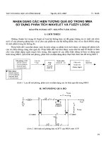
The proposed hybrid (wireless/wired) and hierarchical NoC architecture is shown in
Figure 1 with the augmenting heterogeneous subnets. The hubs are interconnected
via both wireless and wired links while the subnets are wired only. The hubs with
ACM Journal on Emerging Technologies in Computing Systems, Vol. 8, No. 3, Article 23, Pub. date: August 2012.
Performance Evaluation and Design Trade-Offs for Wireless Network-on-Chip
Wireless Link
Embedded Core
Wireless Link
Switch
23:5
Hub
Fig. 1. A hybrid (wireless/wired) hierarchical NoC architecture with heterogeneous subnets and smallworld-based upper-level configuration.
wireless links are equipped with WIs that transmit and receive data packets over the
wireless channels. For inter-subnet data exchange, a packet first travels to its respective
hub and reaches the hub of the destination subnet via the small-world network, where
it is then routed to the final destination core.
There can be various subnet architectures, like mesh, star, ring, etc. Similarly, the basic architecture of the 2nd level of the hierarchy may vary. As an example the hubs may
be connected in a mesh architecture with a few long-range wireless links spread across
them creating a small-world network in the 2nd level of the hierarchy. As case studies,
in this work we consider two types of subnet architectures, namely mesh and star-ring
(a ring architecture with a central hub connecting to every core). Corresponding to each
subnet architecture, we consider two upper-level small-world configurations, mesh and
ring, with long-range wireless shortcuts distributed among the hubs. Thus, the following four hierarchical mm-wave NoC architectures are considered: Ring-StarRing,
Ring-Mesh, Mesh-StarRing, and Mesh-Mesh. As an example, in the Ring-StarRing architecture, the first term (Ring) denotes the upper-level architecture and the second
term (StarRing) indicates that the subnet is a star-ring topology. The same nomenclature applies to the rest of the hierarchical architectures in this article.
3.2. Placement of WIs
The WI placement is crucial for optimum performance gain as it establishes high-speed,
low-energy interconnects on the network. Finding an optimal network topology with a
limited number of WIs is a nontrivial problem with a large search space. It is shown
in Ganguly et al. [2010] that for placement of wireless links in a NoC, the Simulated
ACM Journal on Emerging Technologies in Computing Systems, Vol. 8, No. 3, Article 23, Pub. date: August 2012.
23:6
K. Chang et al.
Number of Hubs,
N
Number of
WIs, n
Initial
probability of
WI setup, Pi,j
Initial Network
configuration
Optimization
Metric
Perform
Simulated
Annealing
Routing
Protocol
Optimal network
configuration
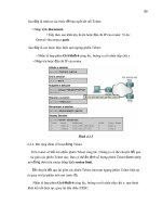
Fig. 2. Flow diagram for the simulated annealing-based optimization of mWNoC architectures.
Annealing (SA) algorithm converges to the optimal configuration much faster than the
exhaustive search technique. Hence, we adopt an SA [Kirkpatrick et al. 1983]-based
optimization technique for placement of the WIs to get maximum benefits of using
the wireless shortcuts. SA offers a simple, well-established, and scalable approach for
the optimized placement of WIs as opposed to an exhaustive search. Initially, the WIs
are placed randomly with each hub having equal probability of getting a WI. The only
constraint observed while deploying the WIs to the hubs is that a single hub could have
a maximum of one WI.
Once the network is initialized randomly, an optimization step is performed using
SA. Since the deployment of WIs is only on the hubs, the optimization is performed
solely on the 2nd -level network of hubs. If there are N hubs in the network and n WIs
to distribute, the size of the search space S is given by
|S| =
N
n
.
(1)
Thus, with increasing N, it becomes increasingly difficult to find the best solution by
exhaustive search. To perform SA, a metric μ is established, which is closely related to
the connectivity of the network. To compute μ , the shortest distances between all pairs
of hubs are computed following the routing strategy outlined in the next section. The
distances are then weighted with a normalized frequency of communication between
the particular pair of hubs. The optimization metric μ can be computed as
μ=
hi j fi j ,
(2)
ij
where hi j is the distance (in hops) between the ith source and jth destination. The
normalized frequency fi j of communication between the ith source and jth destination
is the apriori probability of traffic interactions between the subnets determined by
particular traffic patterns depending upon the application mapped onto the NoC. In
this case, equal weightage is attached to both inter-hub distance and frequency of
communication. The steps used to optimize the network are shown in Figure 2.
An important point to note here is that similar results can also be obtained using
other optimization techniques, like Evolutionary Algorithms (EAs) [Eiben et al. 2003]
and coevolutionary algorithms [Sipper 1997]. Although EAs are generally believed to
give better results, SA reaches comparably good solutions much faster [Jansen et al.
2007]. We have used SA in this work as an example.
ACM Journal on Emerging Technologies in Computing Systems, Vol. 8, No. 3, Article 23, Pub. date: August 2012.
Performance Evaluation and Design Trade-Offs for Wireless Network-on-Chip
23:7
Fig. 3. Zig-zag antenna simulation setup.
4. COMMUNICATION SCHEME
The hubs with WIs are responsible for supporting efficient data transfer between the
distant nodes within the mWNoC by using the wireless communication channel. In
this section we describe the various components of the WIs and the adopted data
routing strategy. The two principal components of the WIs are the antenna and the
transceiver. Characteristics of these two components are discussed in Sections 4.1 and
4.2, respectively.
4.1. On-Chip Antennas
To be effective for the mWNoC application the on-chip antenna must be wideband,
highly efficient, and sufficiently small. It has to provide the best power gain for the
smallest area overhead. A metal zig-zag antenna [Floyd et al. 2002] has been demonstrated to possess these characteristics. This antenna also has negligible effect of rotation (relative angle between transmitting and receiving antennas) on received signal
strength, making it most suitable for mWNoC application [Zhang et al. 2007]. The
zig-zag antenna is designed with 10 μ m trace width, 60 μ m arm length, and 30◦ bend
angle. The axial length depends on the operating frequency of the antenna which is
determined in Section 5.1. The details of the antenna simulation setup and antenna
structure are shown in Figure 3.
4.2. Wireless Transceiver Circuit
The design of a low-power wideband wireless transceiver is the key to guarantee the
desired performance of the mWNoC. Therefore, at both architecture and circuit levels of the transceiver, low-power design considerations were taken into account. As
illustrated in the transceiver architecture diagram in Figure 4, the transmitter (TX)
circuitry consists of an up-conversion mixer and a Power Amplifier (PA). At the receiver
(RX) side, direct-conversion topology is adopted, which consists of a Low Noise Amplifier
(LNA), a down-conversion mixer, and a baseband amplifier. An injection-lock VoltageControlled Oscillator (VCO) is reused for TX and RX. With both direct-conversion and
injection-lock technologies, a power-hungry Phase-Lock Loop (PLL) is eliminated in
the transceiver [Kawasaki et al. 2010]. Moreover, at circuit level, body-enabled design
techniques [Deen et al. 2002], including both Forward Body-Bias (FBB) with DC voltages, as well as body-driven by AC signals [Kathiresan et al. 2006], are implemented
in most of the circuit subblocks to further decrease their power consumptions.
ACM Journal on Emerging Technologies in Computing Systems, Vol. 8, No. 3, Article 23, Pub. date: August 2012.
23:8
K. Chang et al.
Fig. 4. Block diagram of the mm-wave direct-conversion transceiver with injection-lock VCO.
Fig. 5. Schematic of the body-biased LNA with a feed-forward path for bandwidth extension.
The LNA is a crucial component in the RX chain as it determines the sensitivity of
the entire receiver. To achieve a wide bandwidth, a novel feed-forward path is implemented. Moreover, using body-enabled design, low power consumption is maintained.
Figure 5 demonstrates the circuit topology of the proposed low-power wideband LNA,
consisting of three stages. A Common-Source (CS) amplifier with inductive source degeneration is chosen for the first stage since it has better noise performance than the
cascode topology. At the drain of the transistor M1 , inductors L3 and L4 form a bridgedshunt-series peaking structure that serves to extend the bandwidth [Shekhar et al.
2006]. The second stage employs a cascode topology to enhance the overall gain and
reverse isolation of the LNA. Inductor L5 is adjusted to peak the gain at a slightly different frequency from the first stage, realizing a wideband overall frequency response.
Moreover, a feed-forward path, which can boost up the gain of the first stage, is introduced in the third stage, directly coupling the gate of M2 to M4 [Yu et. al. 2010]. With
the peak gain of the second stage set at a higher frequency than that of the first stage,
this feed-forward path extends the bandwidth of the entire LNA at the lower end.
Moreover, the feed-forward path only causes trivial degradation to the overall Noise
Figure (NF) of the LNA, since the noise introduced by M4 is suppressed by the gain of
the first stage. In addition, M4 reuses the bias current with M5 , hence no extra power
consumption is introduced.
As can be seen in Figure 5, FBB is implemented in the last two stages of the LNA.
The threshold voltage of an NMOS transistor can be expressed as [Sedra et al. 2004]
Vt = Vt0 + γ
2φ F + VSB −
2φ F ,
ACM Journal on Emerging Technologies in Computing Systems, Vol. 8, No. 3, Article 23, Pub. date: August 2012.
Performance Evaluation and Design Trade-Offs for Wireless Network-on-Chip
23:9
Fig. 6. Schematic of the body-driven down-conversion mixer with body-biased dummy switching pair for
LO-feedthrough cancellation.
Fig. 7. Circuit topology of the low-power wideband body-biased PA.
where VSB is the voltage between body and source terminals, Vt0 is the threshold
voltage when VSB = 0, γ is a process-dependent parameter, and φ F is the bulk Fermi
potential. This indicates that by applying a positive bias voltage at the body terminal,
the threshold voltage of the NMOS can be effectively decreased without degradations
in device characteristics in terms of gain, linearity, and noise figure [Deen et al. 2002].
Accordingly, in the second stage of the LNA, since the source voltages of M2 and M3
are different, two different DC voltage levels are generated by the bias voltage VB
and the voltage divider RB1 and RB2 , and applied to the body terminals of M2 and
M3 , respectively. The FBB in the third stage is implemented in a similar way. This
decreases the threshold voltages of these transistors, and hence the supply voltage is
reduced from 1 V to 0.8 V.
The down-conversion mixer shown in Figure 6 uses a bulk-driven topology to save
power without sacrificing the performance. Since the body terminal acts as a “backgate”, the RF signal is directly fed into the body terminals of the switching pair. In
this way, not only the switching pair can be biased at very low DC current, the removal of the stacked transconductance stage also leads to a lower supply voltage. In
addition, in order to eliminate Local Oscillator (LO) feed through at the Intermediate
Frequency (IF) port, a novel body-biased dummy switching pair consisting of M3 and
M4 is introduced. By adjusting the body-bias voltage of the dummy pair, the level of
LO cancellation can be optimized.
At the TX side, due to the short communication range of the mWNoC, the required
PA output power is much lower than in conventional mm-wave power amplifiers. Nevertheless it still needs to maintain a wide bandwidth for the required high data rate.
The circuit topology of the proposed three-stage PA is shown in Figure 7. The cascode
structure is used in the first stage for its high gain and better reverse isolation. Similar to the LNA design, FBB is implemented in the cascode stack to lower the power
ACM Journal on Emerging Technologies in Computing Systems, Vol. 8, No. 3, Article 23, Pub. date: August 2012.
23:10
K. Chang et al.
Fig. 8. The body-driven up-conversion mixer circuit.
Fig. 9. The body-biased injection-lock VCO circuit.
consumption of the PA. The other two are both CS stages, which can provide larger voltage headroom and thus better linearity. Moreover, for bandwidth extension, inductive
peaking is created by L2 and L4 at the output of the first and the second stages, respectively. Note that the bias current densities of the last two stages are set to around 0.3
mA/μm for maximum linearity [Yao et al. 2007]. A body-driven double-balanced mixer
serves as the up-conversion mixer. As depicted in Figure 8, the baseband signal is fed
into the body terminals of the switching pair, modulating the 55-GHz carrier signal.
The proposed schematic of the injection-lock VCO is shown in Figure 9. The injection
locking technique [Razavi 2004] not only lowers the phase noise, but also reduces the
frequency and phase variation in the VCO without the use of a PLL. Moreover, FBB is
applied at the body terminals of all the transistors to lower their threshold voltages, so
that a lower bias voltage can be used to decrease the power consumption. As shown in
the schematic, transistors M1 and M2 form a NMOS cross-coupled pair. Transistor M3
acts as a tail current source as well as signal injection point for the VCO. Furthermore,
in order to achieve a desirable locking range for the VCO, an injection amplifier M4 is
also implemented to boost the signal before being fed into M3 .
4.3. Adopted Routing Strategy
In this proposed hierarchical NoC, intra-subnet data routing is done depending on the
topology of the subnet. In this work, we consider two subnet topologies (i.e., mesh and
star-ring). In a mesh subnet, the data routing follows a deadlock-free dimension order
(e-cube) routing. In a star-ring subnet, if the destination core is within two hops on the
ring from the source, then the flit is routed along the ring. If the destination is more
than two hops away, then the flit goes through the central hub to its destination. Thus,
within the star-ring subnet, each core is at a distance of at most two hops from any
other cores. To avoid deadlock, we adopt the virtual channel management scheme from
ACM Journal on Emerging Technologies in Computing Systems, Vol. 8, No. 3, Article 23, Pub. date: August 2012.
Performance Evaluation and Design Trade-Offs for Wireless Network-on-Chip
23:11
Fig. 10. An example of token-flow-control-based distributed routing.
Red Rover algorithm [Draper et al. 1997], in which the ring is divided into two equal
sets of contiguous nodes. Messages originating from each group of nodes use dedicated
virtual channels. This scheme breaks cyclic dependencies and prevents deadlock.
Inter-subnet data routing, however, requires the flits to use the upper-level network consisting of wired and wireless links. By using the wireless shortcuts between
the hubs with WIs, flits can be transferred in a single hop between them. If the
source hub does not have a WI, the flits are routed to the nearest hub with a WI via
the wired links and are then transmitted through the wireless channel. Likewise, if the
destination hub does not have a WI, then the hub nearest to it with a WI receives the
data and routes it to the destination through wired links. Between a pair of source and
destination hubs without WIs, the routing path involving the wireless medium is chosen if it reduces the total path length compared to the wired path. This can potentially
give rise to a hotspot situation in all the WIs because many messages try to access
wireless shortcuts simultaneously, thus overloading the WIs and resulting in higher
latency. A token flow control [Kumar et al. 2008a] along with a distributed routing
strategy is adopted to alleviate this problem. Tokens are used to communicate the status of the input buffers of a particular WI to the other nearby hubs, which need to use
that WI for accessing wireless shortcuts. Every input port of a WI has a token and the
token is turned on if the availability of the buffer at that particular port is greater than
a fixed threshold and turned off otherwise. The routing adopted here is a combination
of dimension order routing for the hubs without WIs and South-East routing algorithm
for the hubs with WIs. This routing algorithm is proved to be deadlock free in Ogras
et al. [2006]. Figure 10 shows a particular communication snapshot of a mesh-based
upper-level network where hub 8 wants to communicate with hub 3. First at source 8,
the nearest WI (4 in this case) is identified. Then the routing algorithm checks whether
taking this WI reduces the total hop count. If so, the token for the south input port of
ACM Journal on Emerging Technologies in Computing Systems, Vol. 8, No. 3, Article 23, Pub. date: August 2012.
23:12
K. Chang et al.
hub 4 is checked and this path is taken only if the token is available. If this is not the
case, the message at hub 8 follows dimension order routing towards the destination
and arrives at hub 9. At hub 9, again the shortest path using WIs is searched and
if the token from hub 10 allows the usage of wireless shortcuts, then the message is
routed through hub 10. Otherwise, the message follows dimension order routing and
keeps looking for the shortest path using WIs at every hub until the destination hub
is reached. Consequently, the distributed routing along with token flow control prevents deadlocks and effectively improves performance by distributing traffic though
alternative paths. It is also livelock free since it generates a minimal path towards the
destination, as the adopted routing here ensures that the wireless shortcuts are only
followed if that reduces the hop count between source and destination. As a result, this
routing always tries to find the shortest path and never allows routing away from the
destination.
In a ring-based upper-level network, the same principle of distributed routing and
token flow control is used. The message follows ring routing and keeps looking for the
shortest path with available WI at every hub until the destination hub is reached. As
mentioned before, the ring routing adopted here is based on the Red Rover algorithm
[Draper et al. 1997], which provides deadlock-free routing by dividing the ring into
two equal sectors and using virtual channels. In this case also routing will never allow
any packet to be routed away from the destination and hence the routing is livelock
free.
As all the wireless hubs are tuned to the same channel and can send or receive
data from any other wireless hub on the chip, an arbitration mechanism needs to be
designed in order to grant access to the wireless medium to a particular hub at a given
instant to avoid interference and contention. To avoid the need for a centralized control
and synchronization mechanism, the arbitration policy adopted is a wireless token
passing protocol. It should be noted that the use of the word token in this case differs
from the usage in the aforementioned token flow control. According to this scheme,
the particular WI possessing the wireless token can broadcast flits into the wireless
medium. All other hubs will receive the flit as their antennas are tuned to the same
frequency band. However, only if the destination address matches the address of the
receiving hub is the flit accepted for further routing, either to a core in the subnet of
that hub or to an adjacent hub. The wireless token is forwarded to the next hub with
a WI after all flits belonging to a packet at the current wireless token-holding hub are
transmitted.
5. PERFORMANCE EVALUATION
In this section we characterize the performance of the proposed mWNoC through rigorous simulation and analysis in presence of various traffic patterns. First, we present
the characteristics of the on-chip wireless communication channel by elaborating the
performances of the antenna and the transceiver circuits. Then we describe the detailed
network-level simulations considering various system sizes and traffic patterns.
Figure 11 shows an overview of the performance evaluation setup for a mWNoC. To
obtain the gain and bandwidth of the antennas we use ADS momentum tool [Agilent
2012]. Bandwidth and gain of the antennas are necessary for establishing the required
design specifications for the transceivers. The mm-wave wideband wireless transceiver
is designed and simulated using Cadence tools with TSMC 65-nm standard CMOS process to obtain its power and delay characteristics. The subnet switches and the digital
components of the hubs are synthesized using Synopsys tools with 65-nm standard cell
library from TSMC at a clock frequency of 2.5 GHz. Energy dissipation of all the wired
links are obtained from actual layout in Cadence assuming a 20 mm × 20 mm die area.
ACM Journal on Emerging Technologies in Computing Systems, Vol. 8, No. 3, Article 23, Pub. date: August 2012.
Performance Evaluation and Design Trade-Offs for Wireless Network-on-Chip
23:13
ImplementaƟon of CommunicaƟon Infrastructure
Wireless Transceiver
Implemented using
Cadence tools with 65 nm
CMOS library from TSMC
Metal wires of different
lengths for inter-subnet
and intra-subnet
communicaƟons
Implemented using
Synopsys tools with 65 nm
CMOS library from TSMC
Laid out using Cadence tools
and exact power and delay
numbers are obtained
Simulated Annealing
(SA) based
opƟmized Network
ConfiguraƟon
Power, Delay
Power, Delay
Gain,
Bandwidth
Implemented using
ADS Momentum
Subnet Routers,
Inter-subnet Hubs
Power, Delay
On-Chip Antenna
Throughput,
Latency, Energy
NoC Simulator
Fig. 11. Overview of performance evaluation setup for mWNoC.
-26
-27
S21 in dB
-28
-29
3dB Bandwidth
-30
-31
-32
45
50
55
60
Frequency in GHz
65
70
Fig. 12. Antenna S21 response.
All the power and delay numbers of various components are then fed into the network
simulator to obtain overall mWNoC performance.
5.1. Wireless Channel Characteristics
The metal zig-zag antennas described earlier are used to establish the on-chip wireless
communication channels. Figure 3 shows the simulation setup for on-chip wireless
antennas. High resistivity silicon substrate (ρ = 5 k -cm) is used for the simulation. In
our experimental setup, depending on the architecture of the 2nd level of the hierarchy,
the maximum distance between a transmitter and receiver pair is 18 mm and for the
antenna simulations this communication range is used. The forward transmission gain
(S21) of the antenna is shown in Figure 12. For optimum power efficiency, the quarter
wave antenna needs an axial length of 0.38 mm in the silicon substrate.
As shown in Figure 11 earlier, the mm-wave wideband wireless transceiver is designed and simulated using TSMC 65-nm standard CMOS process. The overall conversion gain and Noise Figure (NF) of the receiver, including the proposed LNA and
mixer, are shown in Figure 13. The VCO generated −5 dBm of output power, and the
ACM Journal on Emerging Technologies in Computing Systems, Vol. 8, No. 3, Article 23, Pub. date: August 2012.
23:14
K. Chang et al.
6.5
Noise Figure (dB)
22
Conversion Gain (dB)
20
18
16
14
12
10
8
45
50
55
60
Frequency (GHz)
65
6
5.5
5
55
57
59
61
63
Frequency (GHz)
(a)
65
(b)
Fig. 13. Simulated (a) gain, and (b) double-sideband NF of the receiver.
18
Conversion Gain (dB)
16
14
12
10
8
6
4
2
40
45
50
55
60
Frequency (GHz)
65
70
Fig. 14. Simulated TX conversion gain.
LO frequency was set to 55 GHz, in accordance with the center frequency of the LNA’s
pass-band. The conversion gain is 20 dB at the center frequency, and rises up to 20.5 dB
at the peak. This indicates that the mixer contributes around 7 dB of conversion gain.
Figure 13(a) also shows that the overall 3-dB bandwidth of the receiver front-end is
18 GHz. From Figure 13(b), it can be seen that the overall NF stays below 6 dB.
Note that double sideband (DSB) NF is used since the proposed receiver has a directconversion structure. The LNA and the mixer drain 10.8 mA and 0.75 mA of current,
respectively, from the 0.8 V DC bias. Accordingly, the aggregate power consumption of
the receiver front-end is 9.24 mW.
The conversion gain of the transmitter is illustrated in Figure 14. The transmitter
has a peak gain of 15 dB, and a 3-dB bandwidth of 18.1 GHz. Furthermore, circuit
simulation also shows that the output 1-dB gain compression point (P1dB ) of the transmitter is 0 dBm. With the implementation of body-enabled design in both the PA and
up-conversion mixer, the TX front-end consumes only 14 mW from a 0.8-V supply
voltage.
The achieved aggregate power consumption of the entire transceiver is 36.7 mW,
16% lower than the previous design without using body-enabled techniques [Yu et al.
2010; Deb et al. 2010]. It is able to support a data rate of at least 16 Gbps, and a BER
< 10−15 using an OOK modulation scheme.
Using the preceding characteristics of the antennas and mm-wave transceivers, we
carried out a comparative performance analysis between the wireless and wired communication channels. The wired channels are considered to be 32 bits wide, which is
equal to the flit width considered in this article. Each link of the wired channel is
designed with the optimum number of uniformly placed and sized repeaters. Figure 15
ACM Journal on Emerging Technologies in Computing Systems, Vol. 8, No. 3, Article 23, Pub. date: August 2012.
Performance Evaluation and Design Trade-Offs for Wireless Network-on-Chip
23:15
Fig. 15. The variation of energy dissipation per bit with distance for a wired and a wireless link.
presents how energy dissipated per bit changes as a function of length for both wireless
and wired links. From this plot it can be observed that wireless shortcuts are always
energy efficient whenever the link length is 7 mm or more. Moreover, wireless links
eliminate the need to lay out long buffered wire links with many via cuts from the
upper-layer wires all the way down to the substrate. Hence, implementation of longrange links beyond 7 mm using wireless makes the design energy efficient and simpler
in terms of layout. In our implementation, the minimum and maximum distances between the WIs communicating using the wireless channel are 7.07 mm and 18 mm,
respectively. Therefore, in this case, using the wireless channel is always more energy
efficient.
5.2. Network-Level Performance Evaluation
In this section, we analyze the characteristics of the proposed mWNoC and study the
trends in performance as the number of WIs is increased for a particular system.
Our aim is to establish a design trade-off point that helps us in selecting the optimum
number of WIs for certain performance requirements. For our experiments, we consider
three different system sizes, namely 128, 256, and 512 cores, and the die area is kept
fixed at 20 mm × 20 mm in all the cases. The subnet switch architecture is adopted
from Pande et al. [2005]. It has three functional stages, namely, input arbitration,
routing/switch traversal, and output arbitration. Each packet consists of 64 flits. The
input and output ports including the ones on the wireless links have 4 virtual channels
per port, each having a buffer depth of 2 flits. The subnet switches and the hubs handle
the inputs and outputs separately as explained in Dally [1992]. The average message
latency decreases when buffer size increases [Duato et al. 2002]. According to Duato et
al. [2002], the effect of buffer size on performance is small. Moreover, increasing buffer
capacity does not increase performance significantly if messages are longer than the
diameter of the network times the total buffer capacity of a virtual channel (which is
the case for all the system sizes considered in this study) [Duato et al. 2002]. This is
also verified using our own simulations, and the trade-off point for buffer depth that
provides optimum performance without consuming excessive silicon area is obtained
as two flits.
Similar to the intra-subnet communication, we adopt wormhole routing in the wireless channel too. Consequently, the hubs have similar architectures to the NoC switches
in the subnets. Hence, each port of the hub has the same input and output arbiters, and
an equal number of virtual channels with same buffer depths as the subnet switches.
The number of ports in a hub depends on the number of links connected to it. The hubs
ACM Journal on Emerging Technologies in Computing Systems, Vol. 8, No. 3, Article 23, Pub. date: August 2012.
23:16
K. Chang et al.
Fig. 16. Performance variation with change in buffer depth for the ports associated with WIs for a 256-core
Mesh-StarRing system.
also have three functional stages, but as the number of cores increases in a subnet,
the delays in arbitration and switching for some cases are more than a clock cycle.
Depending on the subnet sizes, traversal through these stages needs multiple cycles
and this has been taken into consideration when evaluating overall performance of the
mWNoC. The ports associated with the WIs have an increased buffer depth of 8 flits
to avoid excessive latency penalty while waiting for the token. Increasing the buffer
depth beyond this limit does not produce any further performance improvement for
this particular packet size, but will give rise to additional area overhead. This is shown
in Figure 16 for a 256-core Mesh-StarRing system divided into 16 subnets. The wireless
ports of the WIs are assumed to be equipped with antennas and wireless transceivers.
A self-similar traffic injection process is assumed.
The network architectures developed earlier are simulated using a cycle-accurate
simulator. The delays in flit traversals along all the wired interconnects that enable the
proposed hybrid NoC architecture are considered when quantifying the performance.
These include the intra-subnet core-to-hub wired links and the inter-hub links in the
upper level of the network. The delays through the switches and inter-switch wires of
the subnets and the hubs are taken into account as well.
To quantify the energy dissipation characteristics of the proposed mWNoC architecture, we determine the packet energy dissipation, E pkt . The packet energy is the energy
dissipated on average by a packet from its injection at the source to delivery at the
destination. This is calculated as
Nintrasubnet Esubnet,hophsubnet + Nintersubnet Es−w hs−w
Epkt =
,
Nintrasubnet + Nintersubnet
where Nintrasubnet and Nintersubnet are the total number of packets routed within the
subnet and between the subnets, respectively, Esubnet,hop is the energy dissipated by a
packet traversing a single hop on the wired subnet including a wired link and a switch,
and Es−w is the energy dissipated by a packet traversing a single hop on the 2nd level
of the mWNoC network, which has the small-world property. The average number of
hops per packet in the subnet and the upper-level small-world network are denoted by
hsubnet and hs−w respectively.
To determine the optimum division of the proposed hierarchical architecture in terms
of achievable bandwidth, we evaluate the performance by dividing the whole system
in various alternative ways. Figure 17 shows the achievable bandwidth for a 256-core
Mesh-StarRing mWNoC divided into different numbers of subnets. As can be seen from
the plot, the division of the whole system into 16 subnets with 16 cores in each performs
the best. Similarly, the suitable hierarchical division that achieves best performance is
ACM Journal on Emerging Technologies in Computing Systems, Vol. 8, No. 3, Article 23, Pub. date: August 2012.
Performance Evaluation and Design Trade-Offs for Wireless Network-on-Chip
23:17
Fig. 17. Bandwidth of a 256-core Mesh-StarRing mWNoC for various hierarchical configurations.
Fig. 18. Achievable bandwidth and energy trade-offs for Mesh-Mesh and Mesh-StarRing architectures with
varying number of WIs.
Fig. 19. Achievable bandwidth and energy trade-offs for Ring-Mesh and Ring-StarRing architectures with
varying number of WIs.
determined for all the other system sizes. For system sizes of 128 and 512, the optimum
number of subnets turns out to be 8 and 32, respectively.
Figures 18 and 19 show the achievable bandwidth and packet energy trade-offs of the
proposed mWNoC with varying number of WIs under uniform random spatial traffic
distribution for the three system sizes of 128, 256, and 512 cores divided into 8, 16,
and 32 subnets, respectively. Figure 18 considers two specific architectures (i.e., MeshMesh and Mesh-StarRing), where the upper levels are mesh-based topologies, and the
ACM Journal on Emerging Technologies in Computing Systems, Vol. 8, No. 3, Article 23, Pub. date: August 2012.
23:18
K. Chang et al.
subnets are Mesh and StarRing, respectively. Figure 19 represents the characteristics
of Ring-Mesh and Ring-StarRing architectures. It can be observed that, for all system
sizes and architectures, the bandwidth increases as we start placing more WIs in the
system initially, then it reaches a saturation point and starts decreasing. Placing more
WIs in the system beyond a certain threshold has negative impact on system performance. This happens because the wireless communication channel is a shared medium.
As explained in Section 4.3 before, each WI needs to obtain a token to access the wireless
channel. Since there is only one wireless token circulating among all the WIs, as the
number of WIs goes up, the delay in acquiring the wireless medium for a particular WI
increases. Consequently, it degrades the overall system performance. Moreover, as the
number of WIs increases, the overall energy dissipation from the WIs becomes higher,
and it causes the packet energy to increase as well. Considering all these factors, we
can find the optimum number of WIs corresponding to each system size.
From our experiments we find that the overall bandwidth reaches a maximum with
4, 6, and 10 WIs for 128, 256, and 512 core systems, respectively. Beyond this limit, the
bandwidth degrades, but the energy dissipation continues to increase. This study helps
us to determine the optimum number of WIs for each system size. It is also evident
that the Mesh-StarRing architecture always outperforms Mesh-Mesh architecture as
it has better connectivity in the subnets. It results in lower packet energy for the
Mesh-StarRing architecture compared with Mesh-Mesh architecture. The same trend
is also observed in the architectures with ring-based upper levels, where systems with
StarRing subnets always achieve higher bandwidth than those with Mesh subnets. In
terms of upper-level topologies, systems with a mesh-based upper level always perform
better and have lower packet energy than those with ring-based upper-level due to a
more efficient upper-level network. These advantages of the mesh-based upper-level
network come at the cost of extra wiring overhead. For a 256-core system, a mesh-based
upper-level network has 24 wired links whereas a ring-based counterpart only has 16
wired links, or 33% less links. The new Mesh-StarRing architecture along with the
routing mechanism elaborated in Section 4.3 results in 14.6% bandwidth improvement
and 48% saving in packet energy for a 256-core system with 6 WIs in comparison with
our previous work [Deb et al. 2010].
5.3. Comparative Performance Evaluation with Other Interconnect Technologies
In this section, we consider two other possible interconnect technologies, namely, RF-I
and G-line, that can be used as long-range links in the proposed hierarchical smallworld architecture. Here, we consider a 256-core Mesh-StarRing architecture, and
undertake a comparative study to establish the relative performance benefits achieved
by using these alternatives as long-range shortcuts in the upper-level small-world
network. We first design a small-world NoC (RFNoC) using RF-I links as the shortcuts,
maintaining the same hierarchical topology. As mentioned in Chang et al. [2008], in
65-nm technology it is possible to have 8 different frequency channels each operating
with a data rate of 6 Gbps. Like the wireless channel, these RF links can be used
as the long-range shortcuts in the hierarchical NoC architecture. These shortcuts are
optimally placed using the same SA-based optimization as used for placing the WIs in
the mWNoC. The optimum locations of the hubs with RF-I interfaces are not the same
as those of mWNoC due to the difference in their characteristics. Next, we construct a
small-world NoC (GLNoC) by replacing the shortcuts of RFNoC by G-lines [Mensink
et al. 2007], and still maintain the same hierarchical topology. Each G-line uses a
capacitive preemphasis transmitter that increases the bandwidth and decreases the
voltage swing without the need of an additional power supply. To avoid cross-talk,
differential interconnects are implemented with a pair of twisted wires. A decision
feedback equalizer is employed at the receiver to further increase the achievable data
ACM Journal on Emerging Technologies in Computing Systems, Vol. 8, No. 3, Article 23, Pub. date: August 2012.
Performance Evaluation and Design Trade-Offs for Wireless Network-on-Chip
23:19
Fig. 20. Implementation details of different NoC shortcuts.
Fig. 21. Comparative analysis of hierarchical small-world NoCs with three types of long-range shortcuts
with uniform random traffic.
rate. Each G-line can sustain a bandwidth of around 2.5 Gbps for a wire length of
11 mm. The exact implementation details for the NoC architectures with different
shortcuts are shown in Figure 20.
Figure 21 shows the overall system bandwidth and packet energy dissipation for
mWNoC, RFNoC, and GLNoC in a 256-core Mesh-StarRing system under uniform
random traffic. A 256-core flat mesh is also included for comparison. Compared to the
flat mesh architecture, the three hierarchical NoCs achieve much higher bandwidth
and consume significantly less energy. This is because a hierarchical network reduces
the average hop count, and hence improves the performance. Moreover, packets get
routed faster and hence occupy resources for less time and dissipate less energy in the
process. The energy dissipation for G-line and RFI is obtained from Chang et al. [2008]
and Mensink et al. [2007] respectively. It can be observed that, among the three types
of small-world NoCs, GLNoC has the lowest bandwidth and highest packet energy.
The length of the shortcuts is more than 11 mm and hence the G-line communication
essentially becomes multihop. Consequently, this reduces the overall achievable bandwidth for GLNoC. In addition, the high capacitance of G-line links causes more energy
ACM Journal on Emerging Technologies in Computing Systems, Vol. 8, No. 3, Article 23, Pub. date: August 2012.
23:20
K. Chang et al.
Fig. 22. (a) 256-core system with mesh-based upper-level architecture. (b) 256-core system with ring-based
upper-level architecture.
dissipation. Though mWNoC and RFNoC have the same hierarchical architecture, the
latter performs better because in RFNoC multiple shortcuts can work simultaneously
whereas in mWNoC only one pair can communicate at a particular instant of time since
the wireless channel is a shared medium. But the long-range link area overhead and
layout challenges of the RFNoC will be more than that of the mWNoC. For example,
in case of a 20 × 20 mm2 die, an RF interconnect of approximately 100 mm length
has to be laid for RFNoC. This is significantly higher than the combined length of all
the antennas used in mWNoC, which is 3.8 mm for the highest system size (512-core
system with 10 WIs) considered in this article. A detailed link area overhead analysis
for all the different NoC architectures is presented in Section 5.5.
5.4. Performance Evaluation with Nonuniform Traffic
In order to evaluate the performance of the proposed mWNoC architecture with nonuniform traffic patterns, we consider both synthetic, and application-based traffic distributions. In the following analysis, the system size considered is 256 (with 16 subnets
and 16 cores per subnet), and the number of WIs is chosen to be 6 as obtained from
Section 4.2. The WIs are placed optimally depending on the particular traffic scenario
following the algorithm discussed in Section 3.2.
We consider two types of synthetic traffic to evaluate the performance of the proposed
mWNoC architecture. First, a transpose traffic pattern [Ogras et al. 2006] is considered
where a certain number of hubs communicate more frequently with each other. We have
considered 3 such pairs of subnets and 50% of packets generated from one of these
subnets are targeted towards the other in the pair. The other synthetic traffic pattern
considered was the hotspot [Ogras et al. 2006], where each hub communicates with a
certain number of hubs more frequently than with the others. We have considered three
such hotspot locations to which all other hubs send 50% of the packets that originate
from them. To represent a real application, a 256-point Fast Fourier Transform (FFT)
is considered on the same 256-core mWNoC subdivided into 16 subnets. Each core is
considered to perform a 2-point radix 2 FFT computation. The traffic pattern generated
in performing multiplication of two 128 × 128 matrices is also used to evaluate the
performance of the mWNoC.
Figure 22 presents the bandwidth and packet energy for different traffic patterns.
The same performance-energy trade-off trend as with the uniform random traffic is
observed in this case also. The architectures with mesh-based upper levels always
outperform the architectures with ring-based upper levels. Systems with StarRing
subnets also perform better than those with Mesh subnets.
We also evaluate the performance of a 256-core Mesh-StarRing mWNoC with respect to a corresponding RFNoC and GLNoC of the same size in the presence of the
aforementioned application-specific traffic patterns. As shown in Figure 23, the same
ACM Journal on Emerging Technologies in Computing Systems, Vol. 8, No. 3, Article 23, Pub. date: August 2012.
Performance Evaluation and Design Trade-Offs for Wireless Network-on-Chip
23:21
Fig. 23. Comparison of the three types of hierarchical small-world NoC architectures with nonuniform
traffic patterns.
Fig. 24. Total silicon area for 256-core mWNoC, RFNoC, and GLNoC.
bandwidth and energy dissipation trend is observed as in the uniform random traffic
case.
5.5. Area Overheads
In this subsection, we quantify the area overhead for the hierarchical mWNoC as
well as for the RFNoC and the GLNoC studied in the previous section. In mWNoC,
the antenna used is a 0.38 mm long zig-zag antenna. The area of the transceiver circuits required per WI is the total area required for the OOK modulator/demodulator,
LNA, PA, and VCO. The total area overhead per wireless transceiver turns out to be
0.3 mm2 for the selected frequency range. The digital part for each WI, which is very
similar to a traditional wireline NoC switch, has an area overhead of 0.40 mm2 . Therefore, total circuit area overhead per hub with a WI is 0.7 mm2 . The transceiver area
overhead for RF-I and G-line are taken from Chang et al. [2008] and Mensink et al.
[2007] respectively. Total silicon area overheads for mWNoC, RFNoC, and GLNoC in
a 256-core Mesh-StarRing system are shown in Figure 24. The required silicon area
is largely dominated by the intra-subnet switches associated with the NoC architectures. The area overheads arising due to the hubs along with the required transceivers
for different shortcuts are shown separately. The hub area is dominated by the nontransceiver digital components. Though the transceiver areas of the mm-wave wireless
links, RF-I, and G-line vary, the digital components of the hubs are the same irrespective of the particular interconnect technology used. Consequently, the overall hub
area overhead does not vary much depending on the interconnect technology. This is
ACM Journal on Emerging Technologies in Computing Systems, Vol. 8, No. 3, Article 23, Pub. date: August 2012.
23:22
K. Chang et al.
Fig. 25. Area overhead and performance degradation trade-off with decreasing the number of connections
of each hub for a 256-core mWNoC.
Fig. 26. Total wiring requirements for 256-core mWNoC, RFNoC, and GLNoC.
also clearly evident from the plots of Figure 24. By decreasing the number of coreto-hub direct connections in each subnet the hub area overhead can be reduced. But
that will result in performance degradation. In Figure 25, we show the area overheadperformance degradation due to decreasing the number of connections of each hub. It is
clear that by reducing the number of core-to-hub direct connections the hub area overhead reduces but it also significantly affects the overall achievable bandwidth of the
system.
All the three hierarchical NoC architectures have varying link area requirements.
Figure 26 shows the wiring overhead of the three NoCs (i.e., mWNoC, RFNoC, GLNoC)
built upon a 256-core Mesh-StarRing architecture in a 20 mm × 20 mm die. The wiring
requirements for a flat mesh architecture are shown for comparison. In Figure 26, it is
obvious that RFNoC requires an additional 100 mm wire to establish long-range shortcuts in the upper level compared to mWNoC. Similarly, GLNoC also requires several
additional long wires as the long-range shortcuts. In mWNoC, long-range communication is predominantly done by wireless links and as a result there is no requirement of
long wires as can be seen from Figure 26. It may be noted that in the hierarchical NoC
ACM Journal on Emerging Technologies in Computing Systems, Vol. 8, No. 3, Article 23, Pub. date: August 2012.
Performance Evaluation and Design Trade-Offs for Wireless Network-on-Chip
23:23
architectures, there are no inter-subnet direct core to core links. Hence, all the three
hierarchical NoC architectures eliminate a number of wireline links along the subnet
boundaries which are present in the flat mesh topology.
6. CONCLUSIONS
The Network-on-Chip (NoC) is an enabling methodology to integrate large numbers of
embedded cores on a single die. The existing method of implementing a NoC with planar
metal interconnects is deficient due to high latency and significant power consumption
arising out of multihop links used in data exchanges. One of the promising ways to address this is to replace multihop wired interconnects with high-bandwidth single-hop
long-range millimeter (mm)-wave wireless links. Through a detailed performance evaluation, we establish the relevant design trade-offs for various mm-wave wireless NoC
(mWNoC) architectures. A detailed comparison of hierarchical NoCs based on wireless,
RF-I, and G-line links shows their respective merits and limitations. It is shown that in
mWNoC, by adopting a hierarchical and small-world architecture incorporating bodybiased on-chip wireless links, the performance improves significantly without unduly
large area overhead compared to more conventional wire line counterparts.
REFERENCES
AGILENT 2012. Advanced Design System (ADS).
ALBERT, R. AND BARABASI, A.-L. 2002. Statistical mechanics of complex networks. Rev. Modern Phys. 74, 47–97.
BRANCH, J., GUO, X., GAO, L., SUGAVANAM, A., LIN, J.-J., AND O, K. K. 2005. Wireless communication in a flip-chip
package using integrated antennas on silicon substrates. IEEE Electron. Dev. Lett. 26, 2, 115–117.
BUCHANAN, M. 2003. Nexus: Small Worlds and the Groundbreaking Theory of Networks. W.W. Norton &
Company, Inc.
CHANG, M. F., CONG, J., KAPLAN, A., NAIK, M., REINMAN, G., SOCHER, E., AND TAM, S.-W. 2008. CMP network-onchip overlaid with multi-band RF-interconnect. In Proceedings of the IEEE International Symposium on
High-Performance Computer Architecture (HPCA ’08). 191–202.
DALLY, W. J. 1992. Virtual channel flow control. IEEE Trans. Parallel Distrib. Syst., 3, 2, 194–205.
DEB, S., GANGULY, A., CHANG, K., PANDE, P. P., BELZER, B., AND HEO, D. 2010. Enhancing performance of
network-on-chip architectures with millimeter-wave wireless interconnects. In Proceedings of the IEEE
International Conference on ASAP. 73–80.
DEEN, M. J. AND MARINOV, O. 2002. Effect of forward and reverse substrate biasing on low-frequency noise in
silicon PMOSFETs. IEEE Trans. Electron. Dev. 49, 3, 409–413.
DRAPER, J. AND PETRINI, F. 1997. Routing in bidirectional k-ary n-cube switch the red rover algorithm. In
Proceedings of the International Conference on Parallel and Distributed Processing Techniques and
Applications. 1184–93.
DUATO, J., YALAMANCHILI, S., AND NI, L. 2002. Interconnection Networks—An Engineering Approach. Morgan
Kaufmann.
EIBEN, A. E. AND SMITH, J. E. 2003. Introduction to Evolutionary Computing. Springer Berlin.
FLOYD, B. A., HUNG, C.-M., AND O, K. K. 2008. Intra-Chip wireless interconnect for clock distribution implemented with integrated antennas, receivers, and transmitters. IEEE J. Solid-State Circ. 37, 5, 543–552.
GANGULY, A., CHANG, K., DEB, S., PANDE, P. P., BELZER, B., AND TEUSCHER, C. 2010. Scalable hybrid wireless
network-on-chip architectures for multi-core systems. IEEE Trans. Comput. 99, 1.
JANSEN, T. AND WEGENER, I. 2007. A comparison of simulated annealing with a simple evolutionary algorithm
on pseudo-boolean functions of unitation. Theor. Comput. Sci. 386, 73–93
JOSHI, A., BATTEN, C., KWON, Y.-J., BEAMER, S., SHAMIM, I., ASANOVIC, K., AND STOJANOVIC, V. 2009. Silicon-Photonic
clos networks for global on-chip communication. In Proceedings of the 3rd ACM/IEEE International
Symposium on Networks-on-Chip (NOCS ’09). 124–133.
KATHIRESAN, G. AND TOUMAZOU, C. 1999. A low voltage bulk driven down-conversion mixer core. In Proceedings
of the IEEE International Symposium on Circuit and Systems. 598–601.
KAWASAKI, K., AKIYAMA, Y., KOMORI, K., UNO, M., TAKEUCHI, H., ITAGAKI, T., HINO, Y., KAWASAKI, Y., ITO, K., AND
HAJIMIRI, A. 2010. A millimeter-wave intra-connect solution. IEEE J. Solid-State Circ. 45, 12, 2655–2666.
ACM Journal on Emerging Technologies in Computing Systems, Vol. 8, No. 3, Article 23, Pub. date: August 2012.
23:24
K. Chang et al.
KEMPA, K., RYBCZYNSKI, J., HUANG, Z., GREGORCZYK, K., VIDAN, A., KIMBALL, B., CARLSON, J., BENHAM, G.,
WANG, Y., HERCZYNSKI, A., AND REN, Z. 2007. Carbon nanotubes as optical antennae. Adv. Mater. 19,
421–426.
KIRKPATRICK, S., GELATT, JR., C. D., AND VECCHI, M. P. 1983. Optimization by simulated annealing. Sci. 220,
671–680.
KRISHNA, T., KUMAR, A., CHIANG, P., EREZ, M., AND PEH, L.-S. 2008. NoC with near-ideal express virtual
channels using global-line communication. In Proceedings of the IEEE Symposium on High Performance
Interconnects (HOTI ’08). 11–20.
KUMAR, A., PEH, L.-S., AND JHA, N. K. 2008a. Token flow control. In Proceedings of the 41st IEEE/ACM
International Symposium on Microarchitecture (MICRO ’08). 342–353.
KUMAR, A., PEH, L.-S., KUNDU, P., AND JHA, N. K. 2008b. Toward ideal on-chip communication using express
virtual channels. IEEE Micro 28, 1, 80–90.
KURIAN, G., MILLER, J. E., PSOTA, J., EASTEP, J., LIU, J., MICHEL, J., KIMERLING, L. C., AND AGARWAL, A. 2010. Atac:
A 1000-core cache-coherent processor with on-chip optical network. In Proceedings of the Conference on
Parallel Architectures and Compilation Techniques (PACT ’10).
LEE, S.-B., TAM, S.-W., PEFKIANAKIS, I., LU, S., CHANG, M. F., GUO, C., REINMAN, G., PENG, C., NAIK, M.,
ZHANG, L., AND CONG, J. 2009. A scalable micro wireless interconnect structure for CMPs. In Proceedings of ACM Annual International Conference on Mobile Computing and Networking (MobiCom ’09).
20–25.
LIN, J.-J., WU, H.-T., SU, Y., GAO, L., SUGAVANAM, A., BREWER, J. E., AND O, K. K. 2007. Communication using antennas fabricated in silicon integrated circuits. IEEE J. Solid-State Circ. 42, 8, 1678–
1687.
MEHTA, J., BRAVO, D., AND O, K. K. 2002. Switching noise picked up by a planar dipole antenna mounted near
integrated circuits. IEEE Trans. Electro-Magnetic Compat. 44, 5, 282–290.
MENSINK, E., SCHINKEL, D., KLUMPERINK, E., VAN TUIJL, E., AND NAUTA, B. 2007. A 0.28pJ/b 2Gb/s/ch transceiver
in 90nm CMOS for 10mm on-chip interconnects. In Proceedings of the IEEE International Solid-State
Circuits Conference (ISSCC ’07). 414–612.
OGRAS, U. Y. AND MARCULESCU, R. 2006. It’s a small world after all: NoC performance optimization via longrange link insertion. IEEE Trans. VLSI Syst. 14, 7, 693-706.
PANDE, P. P., GRECU, C., JONES, M., IVANOV, A., AND SALEH, R. 2005. Performance evaluation and design trade-offs
for network-on-chip interconnect architectures. IEEE Trans. Comput. 54, 8, 1025–1040.
PANDE, P., CLERMIDY, F., PUSCHINI, D., MANSOURI, I., BOGDAN, P., MARCULESCU, R., AND GANGULY, A. 2011. Sustainability through massively integrated computing: Are we ready to break the energy efficiency wall
for single-chip platforms? In Proceedings of the Desing, Automation and Test in Europe Conference
(DATE’11). 1–6.
PETERMANN, T. AND DE LOS RIOS, P. 2006. Physical realizability of small-world networks. Phys. Rev. E 73,
026114.
RAZAVI, B. 2004. A study of injection locking and pulling in oscillators. IEEE J. Solid-State Circ. 39, 9,
1415–1424.
SEDRA, A. S. AND SMITH, K. C. 2004. Microelectronic Circuits, 5th Ed. Oxford University Press.
SEOK, E. AND KENNETH, K. O. 2005. Design rules for improving predictability of on-chip antenna characteristics in the presence of other metal structures. In Proceedings of the IEEE International Interconnect
Technology Conference. 120–122.
SHACHAM, A., BERGMAN, K., AND CARLONI, L. P. 2008. Photonic networks-on-chip for future generations of chip
multiprocessors. IEEE Trans. Comput. 57, 9, 1246–1260.
SHEKHAR, S., WALLING, J. S., AND ALLSTOT, D. J. 2006. Bandwidth extension techniques for CMOS amplifiers.
IEEE J. Solid-State Circ. 41, 11, 2424–2439.
SIPPER, M. 1997. Evolution of Parallel Cellular Machines: The Cellular Programming Approach. Springer
Berlin.
TEUSCHER, C. 2007. Nature-inspired interconnects for self-assembled large-scale network-on-chip designs.
Chaos 17, 2, 026106, 2007.
U. E. P. AGENCY. 2012. Report to congress on server and data center energy efficiency public law 109–431.
/>WATTS, D. J. AND STROGATZ, S. H. 1998. Collective dynamics of ‘small-world’ networks. Nature 393, 440–
442.
YAO, T., GORDON, M. Q., TANG, K. K. W., YAU, K. H. K., YANG, M.-T., SCHVAN, P., AND VOINIGESCU, S. P. 2007.
Algorithmic design of CMOS LNAs and PAs for 60-GHz radio. IEEE J. Solid-State Circ. 42, 5, 1044–
1056.
ACM Journal on Emerging Technologies in Computing Systems, Vol. 8, No. 3, Article 23, Pub. date: August 2012.
Performance Evaluation and Design Trade-Offs for Wireless Network-on-Chip
23:25
YU, X., SAH, S. P., BELZER, B., AND HEO, D. 2010. Performance evaluation and receiver front-end design for
on-chip millimeter-wave wireless interconnect. In Proceedings of the International Conference on Green
Computing (IGCC ’10). 555–560.
ZHANG, Y. P., CHEN, Z. M., AND SUN, M. 2007. Propagation mechanisms of radio waves over intra-chip channels
with integrated antennas: frequency-domain measurements and time-domain analysis. IEEE Trans.
Antennas Propag. 55, 10, 2900–2906.
ZHAO, D. AND WANG, Y. 2008. SD-MAC: Design and synthesis of a hardware-efficient collision-free QoS-aware
MAC protocol for wireless network-on-chip. IEEE Trans. Comput. 57, 9, 1230–1245.
Received April 2011; revised August 2011; accepted September 2011
ACM Journal on Emerging Technologies in Computing Systems, Vol. 8, No. 3, Article 23, Pub. date: August 2012.