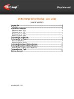
43 draytek vigor 3300v user guide v2 1
Bạn đang xem bản rút gọn của tài liệu. Xem và tải ngay bản đầy đủ của tài liệu tại đây (4.71 MB, 158 trang )
Vigor 3300 Series
Broadband VoIP/Security/Load Balance Router
User’s Guide
Version: 2.1
Date: 2006/08/02
Copyright Information
Copyright
Copyright 2006 All rights reserved. This publication contains information that is
Declarations
protected by copyright. No part may be reproduced, transmitted, transcribed,
stored in a retrieval system, or translated into any language without written
permission from the copyright holders. The scope of delivery and other details
are subject to change without prior notice.
Trademarks
The following trademarks are used in this document:
z
Microsoft is a registered trademark of Microsoft Corp.
z
Windows, Windows 95, 98, Me, NT, 2000, XP and Explorer are
trademarks of Microsoft Corp.
z
Apple and Mac OS are registered trademarks of Apple Computer Inc.
z
Other products may be trademarks or registered trademarks of their
respective manufacturers.
ii
Vigor3300 Series User’s Guide
Table of Contents
1
Preface ...............................................................................................................1
1.1 LED Indicators and Connection .............................................................................................. 2
1.1.1 LED Indicators and Connectors for Vigor3300V .............................................................. 2
1.1.2 LED Indicators and Connectors for Vigor3300................................................................. 4
1.1.3 LED Indicators and Connectors for Vigor3300B+ ............................................................ 6
1.2 Hardware Installation .............................................................................................................. 8
1.2.1 Detailed Explanation for the Connector............................................................................ 9
2
Configuring Basic Settings ............................................................................ 11
2.1 Changing Password ...............................................................................................................11
2.2 Quick Setup........................................................................................................................... 13
2.2.1 Adjusting WAN Connection Mode .................................................................................. 13
2.2.2 Static Mode..................................................................................................................... 15
2.2.3 DHCP Mode.................................................................................................................... 17
2.2.4 PPPoE ............................................................................................................................ 18
2.2.5 PPTP............................................................................................................................... 20
3
Advanced Configuration...................................................................................22
3.1 System setup ........................................................................................................................ 22
3.1.1 Status.............................................................................................................................. 22
3.1.2 Time ................................................................................................................................ 26
3.1.3 Syslog ............................................................................................................................. 27
3.1.4 Access Control................................................................................................................ 28
3.1.5 Configuration Setup ........................................................................................................ 29
3.1.6 Firmware Upgrade Setup................................................................................................ 30
3.1.7 Reboot ............................................................................................................................ 33
3.1.8 Diagnostic Tools ............................................................................................................. 34
3.2 Network Setup....................................................................................................................... 37
3.2.1 WAN and Internet Access Setup .................................................................................... 37
3.2.2 LAN ................................................................................................................................. 44
3.2.3 Load Balance Policy ....................................................................................................... 47
3.2.4 High Availability .............................................................................................................. 48
3.2.5 Static DHCP.................................................................................................................... 50
3.3 Advanced Setup .................................................................................................................... 51
3.3.1 Static Route Setup.......................................................................................................... 52
3.3.2 NAT Setup ...................................................................................................................... 54
3.3.3 RADIUS Setup................................................................................................................ 60
3.3.4 Port Block ....................................................................................................................... 62
3.3.5 DDNS Setup ................................................................................................................... 62
3.3.6 Call Schedule Setup ....................................................................................................... 65
3.3.7 WAN Port Mirroring Setup .............................................................................................. 67
Vigor3300 Series User’s Guide
iii
3.3.8 LAN Port Mirroring Setup................................................................................................ 68
3.3.9 LAN VLAN Setup ............................................................................................................ 68
3.3.10 SNMP............................................................................................................................ 71
3.4 Firewall Setup ....................................................................................................................... 76
3.4.1 IP Filter............................................................................................................................ 76
3.4.2 DoS ................................................................................................................................. 81
3.4.3 URL Filter........................................................................................................................ 83
3.5 Quality of Service Setup........................................................................................................ 88
3.5.1 Incoming/Outgoing Class Setup ..................................................................................... 90
3.5.2 Incoming/Outgoing Class Filter ...................................................................................... 90
3.6 VPN and Remote Access Setup ........................................................................................... 93
3.6.1 IPSec .............................................................................................................................. 94
3.6.2 PPTP............................................................................................................................. 104
3.7 VoIP Setup .......................................................................................................................... 107
3.7.1 Protocol......................................................................................................................... 107
3.7.2 Port Settings ................................................................................................................. 110
3.7.3 Speed Dial .................................................................................................................... 114
3.7.4 Advanced Speed Dial ................................................................................................... 115
3.7.5 Miscellaneous ............................................................................................................... 116
3.7.6 Tone Settings................................................................................................................ 117
3.7.7 QoS............................................................................................................................... 119
3.7.8 NAT Traversal............................................................................................................... 120
3.7.9 Incoming Call Barring ................................................................................................... 121
3.7.10 Call History ................................................................................................................. 123
3.7.11 Status.......................................................................................................................... 124
4
Trouble Shooting ...........................................................................................127
4.1 Checking If the Hardware Status Is OK or Not.................................................................... 127
4.2 Checking If the Network Connection Settings on Your Computer Is OK or Not ................. 128
4.3 Pinging the Router from Your Computer ............................................................................. 131
4.4 Checking If the ISP Settings Are OK or Not........................................................................ 132
4.5 Backing to Factory Default Setting If Necessary ................................................................ 135
4.6 Contacting Your Dealer ....................................................................................................... 136
Appendix A Application for 802.1 VLAN ......................................................................137
A.1 Block LAN-to-LAN Communication .................................................................................... 137
A.2 How to Check/Edit VLAN ID on Your PC?.......................................................................... 138
A.3 Applications......................................................................................................................... 145
A.3.1 Four VLANs for Different Departments in A Company ................................................ 145
A.3.2 Two VLANs for Different Departments in A Company ................................................. 147
A.3.3 Example for the Companies in the Same Building....................................................... 149
A.3.4 Example for A Company and Guest............................................................................. 151
A.3.5 Example for Trunk Usage............................................................................................. 153
iv
Vigor3300 Series User’s Guide
1
Preface
The Vigor3300 Series integrates a rich suite of functions, including NAT, firewall, VPN, load
balance, bandwidth management, and VoIP capability. These products are very suitable for
providing multi-integrated solutions to SME markets. An application scenario for the
Vigor3300 Series is depicted in Figure 1-1, which illustrates interconnections among branch
offices through the Internet via the Vigor3300 Series routers. By combining with an existing
PABX, an Internet phone from a remote branch can also access any extension number on a
local PABX or a traditional phone via PSTN. Also, by combining load balancing, data security,
and Internet phone features, the company can benefit from reducing operation fees.
A Virtual Private Network (VPN) is an extension of a private network that encompasses links
across shared or public networks like an Intranet. A VPN enables you to send data between
two computers across a shared public Internet network in a manner that emulates the
properties of a point-to-point private link. The DrayTek Vigor3300 Series VPN router
supports Internet-industry standards technology to provide customers with open, interoperable
VPN solutions such as X.509, DHCP over Internet Protocol Security (IPSec) up to 200 tunnels,
and Point-to-Point Tunneling Protocol (PPTP).
Internet Telephony, also known as Voice over Internet Protocol (VoIP), is a technology that
allows you to make telephone calls using a broadband Internet connection instead of a regular
(analog) phone line. Combining a PABX with a V3300V allows you to call anyone who has
an Internet phone or a traditional telephone number – including local, long distance, mobile,
and international numbers. Internet Telephony offers features and services that are unavailable
with a traditional phone at no additional cost. Because Internet Telephony requires strictly
minimal packet delay and jitter (since voice quality is intolerant of packet loss), the
Vigor3300V integrates VoIP feature with QoS and packet loss concealment mechanisms to
effectively transport high priority voice traffic over IP with low latency. Another feature is
Vigor3300 Series User’s Guide
1
T.38 fax relay. By enabling and configuring fax rate on a dial peer, the originating and the
terminating V3300V can enter fax relay transfer mode. By using the T.38 function, customers
can also save on fax expenses. Lastly, by enabling the load balance feature on multiple WAN
ports, lease lines can be replaced to provide a cost-effective method for network infrastructure.
1.1 LED Indicators and Connection
The Vigor3300V has 4 WAN interfaces and Vigor3300/3300B+ has 3 WAN interfaces that
support load balancing. This allows the system to reach peak performance and reduces the cost
of maintaining a single high-speed trunk by sharing the load amongst the multiple WAN
interfaces. Each interface can be connected to an individual Internet Service Provider. The
Vigor3300 Series also supports a backup function for WAN interfaces– a user can select one
WAN interface to be a backup interface. If the master interface fails, the backup interface will
take the place of the master interface immediately. Lastly, the Vigor3300V has a DMZ
function can be applied to any LAN or WAN interface.
1.1.1 LED Indicators and Connectors for Vigor3300V
Factory Reset:
Used to restore the default settings. Turn on the router (ACT LED is blinking). Press the hole
and hold for more than 5 seconds. When you see the ACT LED begins to blink rapidly than
usual, release the button. Then the router will restart with the factory default configuration.
LED
Status
Explanation
PWR
On
The router is powered on.
Off
The router is powered off.
On/Blinking
The system is active.
Off
The system is hanged.
On
The VPN tunnel is launched.
Off
The VPN tunnel is closed.
On
The Firewall function is active.
Off
The Firewall function is inactive.
On
The QoS function is active.
Off
The QoS function is inactive.
ACT
VPN
Firewall
QoS
2
Vigor3300 Series User’s Guide
LED
LNK
LAN
(1, 2, 3, 4)
100
FDX
LNK
WAN/DMZ
(1, 2, 3, 4)
100
FDX
Status
Explanation
On
The Ethernet link is established on corresponding port.
Off
No Ethernet link is established.
On
It means that a normal 100 Mbps connection is
through its corresponding port.
Off
It means that a normal 10 Mbps connection is through
its corresponding port.
On
It means a full duplex connection on corresponding
port.
Off
It means a half duplex connection on corresponding
port.
On
The Ethernet link is established.
Blinking
The data transmission is done through the
corresponding port.
Off
No Ethernet link is established.
On
It means that a normal 100Mbps connection is through
its corresponding port.
Off
It means that a normal 10Mbps connection is through
its corresponding port.
On
It means a full duplex connection on corresponding
port.
Off
It means a half duplex connection on corresponding
port.
FXS
FXO
Interface
Description
Console
Provided for technician use.
LAN (P1 ~ P4)
Connecter for local networked devices.
WAN/DMZ (P1 ~ P4)
Connecter for remote networked devices.
FXS
Connecter for telephone set.
FXO
Connecter for FXS interface of PABX.
Vigor3300 Series User’s Guide
3
1.1.2 LED Indicators and Connectors for Vigor3300
LED
Status
Explanation
PWR
On
The router is powered on.
Off
The router is powered off.
On/Blinking
The system is active.
Off
The system is hanged.
WLAN
No
Reserved for future use.
VPN
On
The VPN tunnel is launched.
Off
The VPN tunnel is closed.
On
The Attack function is active.
Off
The Attack function is inactive.
On
The QoS function is active.
Off
The QoS function is inactive.
On
The Ethernet link is established on corresponding port.
Off
No Ethernet link is established.
On
It means that a normal 100 Mbps connection is
through its corresponding port.
Off
It means that a normal 10 Mbps connection is through
its corresponding port.
On
It means a full duplex connection on corresponding
port.
Off
It means a half duplex connection on corresponding
port.
On
The Ethernet link is established.
Blinking
The data transmission is done through the
corresponding port.
Off
No Ethernet link is established.
ACT
Attack
QoS
LNK
WAN
(2, 3, 1)
100M
FDX
LNK
LAN
(1, 2, 3, 4)
4
Vigor3300 Series User’s Guide
LED
100M
FDX
Status
Explanation
On
It means that a normal 100Mbps connection is through
its corresponding port.
Off
It means that a normal 10Mbps connection is through
its corresponding port.
On
It means a full duplex connection on corresponding
port.
Off
It means a half duplex connection on corresponding
port.
Interface
Description
Console
Provided for technician use.
LAN (P1 ~ P4)
Connecter for local networked devices.
WAN/DMZ (WAN1 ~ WAN3)
Connecter for remote networked devices.
Vigor3300 Series User’s Guide
5
1.1.3 LED Indicators and Connectors for Vigor3300B+
LED
Status
Explanation
PWR
On
The router is powered on.
Off
The router is powered off.
On/Blinking
The system is active.
Off
The system is hanged.
On
The Attack function is active.
Off
The Attack function is inactive.
On
The QoS function is active.
Off
The QoS function is inactive.
On
The Ethernet link is established on corresponding port.
Off
No Ethernet link is established.
On
It means that a normal 100 Mbps connection is
through its corresponding port.
Off
It means that a normal 10 Mbps connection is through
its corresponding port.
On
It means a full duplex connection on corresponding
port.
Off
It means a half duplex connection on corresponding
port.
On
The Ethernet link is established.
Blinking
The data transmission is done through the
corresponding port.
Off
No Ethernet link is established.
On
It means that a normal 100Mbps connection is through
its corresponding port.
Off
It means that a normal 10Mbps connection is through
its corresponding port.
ACT
Attack
QoS
LNK
WAN
(2, 3, 1)
100M
FDX
LNK
LAN
(1, 2, 3, 4)
100M
6
Vigor3300 Series User’s Guide
LED
FDX
Status
Explanation
On
It means a full duplex connection on corresponding
port.
Off
It means a half duplex connection on corresponding
port.
Interface
Description
Console
Provided for technician use.
LAN (P1 ~ P4)
Connecter for local networked devices.
WAN1 ~ WAN3
Connecter for remote networked devices.
Connecter Specification
Auxiliary
Cables
Type,
Color
Connected to
Remarks
Power Cord
Black
AC Outlet
90-264VAC
Serial (Console)
RS232, Grey PC RS232 port
--
Ethernet (LAN)
RJ-45, Blue
Ethernet switch or hub
--
Ethernet (DMZ)
RJ-45, Blue
Server
Ethernet (WAN1) RJ-45, Blue
DSL/Cable/Fiber Modem
Ethernet (WAN2) RJ-45, Blue
DSL/Cable/Fiber Modem
Ethernet (WAN3) RJ-45, Blue
DSL/Cable/Fiber Modem
Ethernet (WAN4) RJ-45, Blue
DSL/Cable/Fiber Modem
Vigor3300 Series User’s Guide
--
7
1.2 Hardware Installation
Before starting to configure the router, you have to connect your devices correctly.
1.
Connect the power cord to the power port of Vigor3300 router on the rear panel, and the
other side into a wall outlet.
2.
Power on the device by pressing the power switch on the rear panel. The PWR LED
should be ON.
3.
The system starts to initiate. After completing the system test, the ACT LED will light
up and start blinking.
4.
Connect one end of an Ethernet cable (RJ-45) to one of the LAN ports of Vigor3300.
5.
Connect the other end of the cable (RJ-45) to the Ethernet port on your computer (that
device also can connect to other computers to form a small area network). The LAN
LED for that port on the front panel will light up.
6.
Connect a server/modem/router (depends on your requirement) to any available WAN
port of the device with Ethernet cable (RJ-45). The WAN LED will light up.
7.
Connect telephone sets to the FXS ports of Vigor3300V with telephone lines (RJ-11 to
RJ-11). For the users of Vigor3300 and Vigor3300B+, please skip this step.
8.
Connect the FXO ports to PABX with telephone lines (RJ-11 to RJ-11). For the users of
Vigor3300 and Vigor3300B+, please skip this step.
Below shows an outline of the hardware installation for your reference (take Vigor3300V as
an example).
8
Vigor3300 Series User’s Guide
1.2.1 Detailed Explanation for the Connector
Here provides you detailed explanation for some specific connectors that you have to be
familiar.
The RS232 Connector
The RJ45 connection jet is used for CLI commands for system configuration and control
functions in the Vigor3300 Series. The jet is used for initialization of the Vigor3300 Series
during preliminary installation. The “management cable”, as shown in Figure 1-5, converts the
RJ45 to the RS232 interface. The RJ45 jet connects to a console interface in theVigor3300
Series, while the RS232 DB9 connects to a console port on the computer. The default setting
of the console port is “baud rate 57600, no parity, and 8 bit with 1 stop bit.”
Standard 10/100 Base-T Ethernet Interface Connector
RJ45 jets provide 10/100 Base-T Ethernet interfaces. The interface supports MDI/MDIX
auto-detection of either straight or crossover RJ45 cables. These cables are used on WAN,
LAN, and DMZ interfaces.
Chassis Connections
The Vigor3300 Series can be mounted on a rack by using standard brackets in a 19-inch rack
or optional larger brackets on 23-inch rack (not included). The bracket for 19- and 23-inch
racks are shown below.
Attach the brackets to the chassis of a 19- or a 23-inch rack (as shown in the Figures 1-8 and
1-9). Repeat the above procedure for the second bracket, which attaches the other side of the
chassis.
Vigor3300 Series User’s Guide
9
X
Y
After the bracket installation, the Vigor3300 Series chassis can be installed in a rack by using
four screws for each side of the rack.
Desktop Type Installation
Rubber pads are included with the Vigor3300 Series. These rubber pads improve the air
circulation and decrease unnecessary rubbing on the desktop.
10
Vigor3300 Series User’s Guide
2
Configuring Basic Settings
For use the router properly, it is necessary for you to change the password of web
configuration for security and adjust primary basic settings.
This chapter explains how to setup a password for an administrator and how to adjust basic
settings for accessing Internet successfully.
2.1 Changing Password
To change the password for this device, you have to access into the web browser with default
password first.
1.
Make sure your computer connects to the router correctly.
Notice: You may either simply set up your computer to get IP dynamically from the
router or set up the IP address of the computer to be the same subnet as the default
IP address of Vigor router 192.168.1.1. For the detailed information, please refer
to the later section - Trouble Shooting of this guide.
2.
Open a web browser on your PC and type http://192.168.1.1. A pop-up window will
open to ask for username and password. Please type default values on the window for the
first time accessing. The default value for user name is draytek and the password is 1234.
Next, click OK.
Vigor3300 Series User’s Guide
11
12
3.
Now, the Main Screen will pop up.
4.
Go to System page and choose Change Password.
5.
The following screen will appear.
6.
Enter the login password (1234) on the field of Old Password. Type a new one in the
field of New Password and retype it on the field of Confirm Password. Then click Apply
to continue.
Vigor3300 Series User’s Guide
7.
Now, the password has been changed. Next time, use the new password to access the
Web Configurator for this router.
8.
Next, you will see the login screen after clicking Apply. Please use new password to
re-enter the system configuration.
2.2 Quick Setup
Quick Setup is designed for configuring your broadband router accessing Internet with simply
steps. There are two phases of quick setup, one is WAN configuration and the other is LAN
configuration.
2.2.1 Adjusting WAN Connection Mode
In the Quick Setup group, you can configure the router to access the Internet with different
modes such as Static, DHCP, PPPoE, or PPTP modes. For most users, Internet access is the
primary application. The router supports the Ethernet WAN interface for Internet access. The
following sections will explain in more detail the various broadband access configurations. All
settings in this section will be applied in the first WAN1 interface.
Now, you have to select an appropriate WAN connection type for connecting to the Internet
through this router according to the settings that your ISP provided.
Vigor3300 Series User’s Guide
13
MAC Address
Router DefaultUse the default Mac address stored originally in router.
User DefinitionUse a MAC address defined by the user.
14
Downstream Rate
Assign the downstream rate for this WAN interface. The default
value is 102400 kbps (100 Megabit). This setting is very important
for Vigor3300 Series incoming buffer adjustment. If you use a DSL
subscriber service with a 2Mbps downstream, please set the
downstream rate setting with 2Mbps.
Upstream Rate
Assign the transmission rate for this WAN interface. The default
value is 102400 kbps (100 Megabit). This setting is very important
for Vigor3300 Series outgoing buffer adjustment. If you use a DSL
subscriber service with a 256Kbps downstream, please set the
downstream rate setting with 256Kbps.
Type
Select a connection type for this WAN interface. Currently, there is
only one setting offered for you to choose - Fast Ethernet.
Physical Mode
Select connection speed mode for this WAN interface. There are
auto negotiation, full duplex, and half duplex of either 10M or
100M speed options for the WAN Interface.
IP Mode
Select an IP mode for this WAN interface. There are four available
modes for Internet access, Static, DHCP, PPPoE, and PPTP. On
this page you may configure the WAN interface to use Static (fixed
IP), DHCP (dynamic IP address), PPPoE or PPTP. Most of the
cable users will use the DHCP mode to get a globally reachable IP
address from the cable host system.
Vigor3300 Series User’s Guide
2.2.2 Static Mode
You can manually assign a static IP address to the WAN interface and complete the
configuration by applying the settings and rebooting your router. Choosing Static as the IP
mode, you will see the following page:
All the settings here are set by privately. Your ISP will not provide these settings.
IP Address
Assign a private IP address to the WAN interface.
Subnet Mask
Assign a subnet mask value to the WAN interface.
Default Gateway
Assign a private IP address to the gateway.
Primary DNS
Assign a private IP address to the primary DNS.
Secondary DNS
Assign a private IP address to the secondary DNS.
IP Alias List
Assign other IP addresses to be bound to this interface. This
setting is optional. If you have typed addresses here, you can
see and choose it in later web page settings (e.g., Advanced >>
NAT>>Port Redirection/DMZ Host). Thirty-two IP addresses
settings are allowed at one time.
After setting up the WAN interface, the user can click Next to setup the LAN interface
continuously.
Vigor3300 Series User’s Guide
15
IP Address
Assign an IP address for the LAN interface.
Subnet Mask
Assign the subnet mask for the LAN interface.
Status
Click Enable to use DHCP server; click Disable to close
DHCP server; click Relay Agent to activate relay agent
function.
Start IP
Assign the start IP address of the IP pool that DHCP server can
use for clients in LAN.
End IP
Assign the end IP address of the IP pool that DHCP sever can
use for clients in LAN.
Primary DNS
Type the IP address for primary DNS.
When you finished the above required settings, please click Finish. A system reboot page will
appear. Click Apply to activate the static mode configuration.
16
Vigor3300 Series User’s Guide
2.2.3 DHCP Mode
DHCP allows a user to obtain an IP address automatically from a DHCP server on the Internet.
If you choose DHCP mode, the DHCP server of your ISP will assign a dynamic IP address for
Vigor3300 automatically. It is not necessary for you to assign any setting. (Host Name and
Domain Name are required for some ISPs). S imply click Next to setup LAN interface.
After setting up the WAN interface, the user can click Next to setup the LAN interface
continuously.
IP Address
Assign an IP address for the LAN interface.
Subnet Mask
Assign the subnet mask for the LAN interface.
Status
Click Enable to use DHCP server; click Disable to close
DHCP server; click Relay Agent to activate relay agent
function.
Start IP
Assign the start IP address of the IP pool that DHCP server can
use for clients in LAN.
Vigor3300 Series User’s Guide
17
End IP
Assign the end IP address of the IP pool that DHCP sever can
use for clients in LAN.
Primary DNS
Type the IP address for primary DNS.
When you finished the above required settings, please click Finish. A system reboot page will
appear. Click Apply to activate the DHCP mode configuration.
2.2.4 PPPoE
This mode is used for most of DSL modem users. All local users can share one PPPoE
connection to access the Internet. Your service provider will give you the user name, password,
and authentication mode for PPPoE settings.
If your ISP provides you the PPPoE (Point-to-Point Protocol over Ethernet) connection,
please select PPPoE for this router to get the following page. Enter the username and
password provided by your ISP on the web page.
User Name
Assign a specific valid user name provided by the ISP.
Password
Assign a valid password provided by the ISP.
Authentication
Select PAP or CHAP protocol for PPP authentication. The
default value is PAP.
Service Name
Assign a service name required from ISP service.
After setting up the WAN interface, the user can click Next to setup the LAN interface
continuously.
18
Vigor3300 Series User’s Guide
IP Address
Assign an IP address for the LAN interface.
Subnet Mask
Assign the subnet mask for the LAN interface.
Status
Click Enable to use DHCP server; click Disable to close
DHCP server; click Relay Agent to activate relay agent
function.
Start IP
Assign the start IP address of the IP pool that DHCP server can
use for clients in LAN.
End IP
Assign the end IP address of the IP pool that DHCP sever can
use for clients in LAN.
Primary DNS
Type the IP address for primary DNS.
When you finished the above required settings, please click Finish. A system reboot page will
appear. Click Apply to activate the PPPoE mode configuration.
Vigor3300 Series User’s Guide
19
2.2.5 PPTP
This mode lets user get the IP group information by a DSL modem with PPTP service from
ISP. Your service provider will give you user name, password, and authentication mode for a
PPTP setting.
If your ISP offers you PPTP (Point-to-Point Tunneling Protocol) mode, please select PPTP
for this router. Next, enter the PPTP Subnet Mask (e.g., 255.255.255.0), PPTP Local
Address (e.g., 10.66.99.88) and PPTP Remote Address (e.g., 172.66.99.88) provided by
your ISP on the web page.
PPTP Local Address
Assign a local IP address of PPTP.
PPTP Subnet Mask
Assign a net mask value for IP address of PPTP.
PPTP Remote Address
Assign a remote IP address of PPTP server.
After setting up the WAN interface, the user can click Next to setup the LAN interface
continuously.
20
Vigor3300 Series User’s Guide
IP Address
Assign an IP address for the LAN interface.
Subnet Mask
Assign the subnet mask for the LAN interface.
Status
Click Enable to use DHCP server; click Disable to close
DHCP server; click Relay Agent to activate relay agent
function.
Start IP
Assign the start IP address of the IP pool that DHCP server can
use for clients in LAN.
End IP
Assign the end IP address of the IP pool that DHCP sever can
use for clients in LAN.
Primary DNS
Type the IP address for primary DNS.
When you finished the above required settings, please click Finish. A system reboot page will
appear.
Vigor3300 Series User’s Guide
21