ĐIỆN tử VIỄN THÔNG DALLAS~1 khotailieu
Bạn đang xem bản rút gọn của tài liệu. Xem và tải ngay bản đầy đủ của tài liệu tại đây (48.55 KB, 6 trang )
APPLICATION NOTE 82
Application Note 82
Using the Dallas Tricklecharge Timekeeper
DESCRIPTION
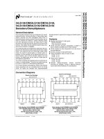
tion. Only three wires are required to communicate with
the clock/RAM: (1) RST (Reset), (2) I/O (Data Line), and
(3) SCLK (Serial Clock). Data can be transferred to and
from the clock/RAM one byte at a time or in a burst of up
to 31 bytes. The DS1302 is designed to operate on very
low power and retain data and clock information on less
than 1 microwatt. The DS1302 is designed to be completely compatible with designs that are currently using
the DS1202. This compatibility allows the DS1302 to be
dropped directly into a DS1202 socket. Then the
optional trickle charge circuit on the DS1302 can be
used to backup the system time and data with a super
cap or a rechargeable battery.
The Dallas Semiconductor DS1302 Trickle Charge
Time Keeping Chip is a programmable 3–wire serial
interface clock with a trickle charge circuit for using both
rechargeable and non–rechargeable backup supplies.
The real time clock/calendar provides seconds, minutes, hours, day, date, month, year information. The
end of the month date is automatically adjusted for
months with less than 31 days, including corrections for
leap year. The clock operates in either the 24–hour or
12–hour format with an AM/PM indicator. The DS1302
also provides 31 bytes of nonvolatile SRAM for data
storage. Interfacing the DS1302 with a microprocessor
is simplified by using a synchronous serial communica-
DS1302 PROGRAMMABLE TRICKLE CHARGER Figure 1
R1
VCC2
R2
VCC1
PIN 1
PIN 8
R3
1 OF 16 SELECT
(NOTE: ONLY 1010 CODE ENABLES CHARGER)
1 OF 2
SELECT
1 OF 3
SELECT
TCS = TRICKLE CHARGE SELECT
TCS
TCS
TCS
TCS
DS
DS
RS
RS
BIT 7
BIT 6
BIT 5
BIT 4
BIT 3
BIT 2
BIT 1
BIT 0
ECopyright 1995 by Dallas Semiconductor Corporation.
All Rights Reserved. For important information regarding
patents and other intellectual property rights, please refer to
Dallas Semiconductor databooks.
DS
= DIODE SELECT
RS
= RESISTOR SELECT
090794 1/6
APPLICATION NOTE 82
TRICKLE CHARGER
The trickle charge circuit is shown in Figure 1 along with
the trickle charge register. To enable the trickle charger
the desired path through the circuit must be selected
and the appropriate pattern written to the trickle charge
register. The trickle charge select (TCS) bits (bits 4 – 7)
control the selection of the trickle charger. In order to
prevent accidental enabling, only a pattern of 1010 will
enable the trickle charger. All other patterns will disable
the trickle charger. The DS1302 powers up with the
trickle charger disabled. The diode select (DS) bits (bits
2 – 3) select whether one diode or two diodes are connected between VCC2 and VCC1. If DS is 01, one diode
is selected or if DS is 10, two diodes are selected. If DS
is 00 or 11 the trickle charger is disabled independent of
TCS. The RS bits (bits 0 – 1) select the resistor that is
connected between VCC2 and VCC1. The resistor
selected by the resistor select (RS) bits is as follows:
RS BITS
RESISTOR
TYPICAL VALUE
00
None
None
01
R1
2KΩ
10
R2
4KΩ
11
R3
8KΩ
If RS is 00 the trickle charger is disabled independent of
TCS.
Diode and resistor selection is determined by the user
according to the maximum current desired for battery or
super cap charging. The maximum charging current
can be calculated as illustrated in the following example.
Assume that a system power supply of 5V is applied to
VCC2 and a super cap is connected to VCC1. Also,
assume that the trickle charger has been enabled with 1
diode and resistor R1 between VCC2 and VCC1. The
maximum current IMAX would therefore be calculated as
follows:
IMAX = (5.0V – diode drop)/R1
~(5.0V–0.7V)/ 2KΩ
~2.2 mA
Obviously, as the super cap charges, the voltage drop
between VCC2 and VCC1 will decrease and therefore the
charge current will decrease (please see curves in
Trickle Charger Characteristics section).
POWER CONTROL
The DS1302 can be powered in several different ways.
The first method, shown in Figure 2, illustrates the
DS1302 being supplied by only one power supply. In
Figure 2a the power supply is connected to VCC2 (pin 1)
and in Figure 2b the power supply is connected to VCC1
(pin 8). In each case the unused power pin, VCC1 or
VCC2, is grounded. The second method, Figure 3, illustrates the DS1302 being backed up using a non–rechargeable battery connected to VCC1. In these two
cases the trickle charge circuit has been disabled. In the
final case, Figure 4, the DS1302 is being backed up by
connecting a super cap, Figure 4a, or a rechargeable
battery, Figure 4b, to VCC1. In this case the trickle
charge circuit has been enabled.
SINGLE POWER SUPPLY OPTION Figure 2
DS1302
DS1302
1
8
VCC2
1
8
VCC2
VCC1
VCC1
4
4
GND
2a
090794 2/6
GND
2b
APPLICATION NOTE 82
NON–RECHARGEABLE BATTERY BACKUP Figure 3
DS1302
1
8
VCC2
VCC1
3V LITHIUM
BATTERY
4
GND
SUPER CAP OR RECHARGEABLE BATTERY BACKUP Figure 4
DS1302
DS1302
1
8
1
VCC1
VCC2
8
VCC1
VCC2
RECHARGABLE
BATTERY
SUPER CAP
4
4
GND
GND
4a
TRICKLE CHARGE CHARACTERISTICS
Charging the Super Cap – As was discussed earlier the
maximum current, IMAX, required by the trickle charge
circuit can be calculated by inserting the correct values
selected in the trickle charge register into the following
equation:
IMAX = (VCC2 – diode drop)/R
Table 1 contains the values of IMAX for VCC2 values of
4.5V, 5.0V and 5.5V; 1 diode drop and 2 diode drops;
resistor values of 2000Ω, 4000Ω and 8000Ω.
Also, the charging current can be modeled as a function
of charge time. Both the super cap voltage and charging
current as a function of time are represented in Figure 5.
The equation to model the super cap voltage as a function of time is
V(t) = VMAX [1–e(–t/RC)]
4b
V(t) – Super Cap Voltage
VMAX – (VCC2 – n Diode Drops), n=1,2
R – Internal Trickle Charge Resistor
C – Super Cap Capacitance
The time needed to charge the super cap to 95% of
VMAX is given in Table 2. Note that the time required to
charge the super cap to 95% of the value of VMAX is
independent of the value of VMAX. The equation which
models the charging current as a function of time is
given as
I(t) = VMAX/R * e(–t/RC)
where:
I(t) – Charging Current
VMAX – (VCC2 – n Diode Drops), n=1,2
R – Internal Trickle Charge Resistor
C – Super Cap Capacitance
where:
090794 3/6
APPLICATION NOTE 82
Discharging the Super Cap – When modeling the
DS1302 for the time to discharge the super cap the
DS1302 characterization data was used to observe that
the ICC1T, Time Keeping Current through VCC1, was linear. This implies that it is proper to represent the
DS1302 as a resistive load, RL, through which the super
cap will be discharged. Using the data sheet spec of
ICC1T max of 0.3 µA at 2.5 VCC1 gives a value for RL of
8.3MΩ. Then the equation modeling the discharging of
the super cap is given by
where:
V(t) – Super Cap Voltage
VMAX – (VCC2 – n Diode Drops), n=1,2
RL – DS1302 Load Resistance
C – Super Cap Capacitance
The calculated values for the time required to discharge
the super cap to 2V are given in Table 3 and a sample of
the super cap voltage as a function of discharge time is
given in Figure 6.
V(t) + V MAX * e (*tńR LC)
CALCULATED VALUES OF IMAX Table 1
2000Ω
4000Ω
8000Ω
VCC2
1 diode
2 diodes
1 diode
2 diodes
1 diode
2 diodes
UNITS
4.5V
1.90
1.55
0.95
0.78
0.48
0.39
mA
5.0V
2.15
1.80
1.08
0.90
0.54
0.45
mA
5.5V
2.40
2.05
1.20
1.03
0.60
0.51
mA
CHARGING TIME FOR SUPER CAP TO 95% OF VMAX Table 2
2000Ω
4000Ω
8000Ω
UNITS
Super Cap=0.047 F
4.7
9.4
18.8
minutes
Super Cap=0.47 F
46.9
93.9
187.7
minutes
Super Cap=1.5 F
149.8
299.6
599.2
minutes
SUPER CAP DISCHARGE TIME TO 2V Table 3
0.047F
0.47F
1.5F
VCC2
1 diode
2 diodes
1 diode
2 diodes
1 diode
2 diodes
UNITS
4.5V
69.8
47.7
698.3
476.8
2228.7
1521.7
hours
5.0V
83.3
63.9
832.8
639.5
2657.9
2040.9
hours
5.5V
95.2
78.1
952.5
780.9
3039.8
2492.5
hours
090794 4/6
APPLICATION NOTE 82
SUPER CAP CHARGING CHARACTERISTICS Figure 5
SUPER CAP CHARGE TIME – 0.47F
4.5
Change Voltage (V)
4.0
3.5
3.0
2.5
2000Ω
4000Ω
8000Ω
2.0
1.5
1.0
0.5
0
0
50
100
150
200
250
300
Charge Time (minutes)
SUPER CAP CHARGE CURRENT – 0.47F
4.5
Charge Current (mA)
4.0
3.5
3.0
2.5
2000Ω
4000Ω
8000Ω
2.0
1.5
1.0
0.5
0
0
50
100
150
200
250
300
Charge Time (minutes)
090794 5/6
APPLICATION NOTE 82
SUPER CAP DISCHARGING CHARACTERISTICS Figure 6
SUPER CAP DISCHARGE TIME
VMAX=4.3V
5.0
Super Cap Voltage (V)
4.5
4.0
0.047F
0.47F
1.5F
3.5
3.0
2.5
2
0
500
1000
1500
2000
2500
Discharge Time (hours)
SUPER CAP DISCHARGE TIME
VMAX=3.6V
5.0
Super Cap Voltage (V)
4.5
4.0
0.047F
0.47F
1.5F
3.5
3.0
2.5
2
0
500
1000
1500
Discharge Time (hours)
090794 6/6
2000
2500