Phát triển phương pháp phần tử hữu hạn đẳng hình học để phân tích và điều khiển đáp ứng kết cấu tấm nhiều lớp
Bạn đang xem bản rút gọn của tài liệu. Xem và tải ngay bản đầy đủ của tài liệu tại đây (10.95 MB, 271 trang )
THE WORK IS COMPLETED AT
HCM CITY UNIVERSITY OF TECHNOLOGY AND EDUCATION
Supervisor 1: Assoc. Prof. Dr NGUYEN XUAN HUNG
Supervisor 2: Assoc. Prof. Dr DANG THIEN NGON
PhD thesis is protected in front of
EXAMINATION COMMITTEE FOR PROTECTION OF DOCTORAL THESIS
HCM CITY UNIVERSITY OF TECHNOLOGY AND EDUCATION,
Date .... month .... year .....
ORIGINALITY STATEMENT
I, Nguyen Thi Bich Lieu, hereby assure that this dissertation is my own
work, done under the guidance of Assoc. Prof. Dr. Nguyen Xuan Hung and Assoc.
Prof. Dr. Dang Thien Ngon with the best of my knowledge.
The data and results stated in the dissertation are honest and were not been
published by any works.
Ho Chi Minh City, October 2019
Nguyen Thi Bich Lieu
i
ACKNOWLEDGEMENTS
This dissertation has been carried out in the Faculty of Civil Engineering, HCM
City University of Technology and Education, Viet Nam. The process of conducting
this thesis brings excitement but has quite a few challenges and difficulties. And I
can say without hesitation that it has been finished thanks to the encouragement,
support and help of my professors and colleagues.
First of all, I would like to express my deepest gratitude to Assoc. Prof. Dr.
Nguyen Xuan Hung and Assoc. Prof. Dr. Dang Thien Ngon, especially Assoc. Prof. Dr.
Nguyen Xuan Hung from CIRTech Institute, Ho Chi Minh City University of
Technology (HUTECH), Vietnam for having accepted me as their PhD student and for
the enthusiastic guidance and mobilization during my research. Also, I would like to
sincerely thank Dr. Thai Hoang Chien, a close brother, for his helpful guidance at first
step of doing research and his support for my overcoming of the hardest time.
Secondly, I would like also to acknowledge Msc. Nguyen Van Nam, Faculty of
Mechanical Technology, Industrial University of Ho Chi Minh City, Vietnam for
their troubleshooting and the cooperation in my study. Furthermore, I am grateful to
Chau Nguyen Khanh and the staffs at CIRTech Institute, HUTECH, Vietnam for
their professional knowledge, interactive discussion, and immediate support.
Thirdly, I take this chance to thank all my nice colleagues at the Faculty of Civil
Engineering, Ho Chi Minh City University of Technology and Education, for their
professional advice and friendly support.
Finally, this dissertation is dedicated to my family, especially my beloved
husband, who has always given me valuable encouragement and assistance.
Nguyen Thi Bich Lieu
ii
ABSTRACT
Isogeometric analysis (IGA) was introduced in 2005 by Hughes et al. [5] as a
breakthrough in numerical simulation. The main advantage of the IGA is to use the
same basis function to describe the geometry and to approximate the problem
unknowns. It integrates Computer Aided Design (CAD) and Computer Aided
Engineering (CAE) and so far the effectively numerical tool for the analysis of a
variety of practical problems. The computational cost is decreased significantly as
the meshes are generated within the CAD. IGA produces the results with higher
accuracy because of the smoothness and the higher-order continuity between
elements. For the last decade of development, isogeometric analysis has surpassed
the standard finite elements in terms of effectiveness and reliability for various
problems, especially for the ones with complex geometry.
Owing to its important role in many engineering structures and modern
industries, laminated plate structures are widely used in a diverse array of structures
in many areas such as aviation, shipbuilding and civil engineering. Laminated plates
have excellent mechanical properties, including high strength to weight and stiffness
to weight ratios, wear resistance, light weight and so on. Besides possessing the
superior material properties, the laminated composites also supply the advantageous
design through the arrangement of the stacking sequence and layer thickness to
obtain the desired characteristics, that’s why they have received considerable
attention of many researchers worldwide.
In this dissertation, an isogeometric finite element formulation is developed based
on Bézier extraction to solve various plate problems, using a seven-dof higher-order
shear deformation theory for both analysis and control the responses of plate structures.
One key point in this dissertation is to exploit the distinctive advantage of Bézier
extraction in analysis of plate structures. In the conventional isogeometric analysis, the
B-spline or Non-uniform Rational B-spline (NURBS) basis functions span over the
entire domain of structures not just a local domain as Lagrangian shape
iii
functions in FEM. The global structure induces the complex implementation in a
traditional finite element context. In addition, in order to compute the shape functions,
the Gaussian integration points force to transform to parametric space. By choosing
Bernstein polynomials as the basis functions, IGA will be performed easily similar to
the way of implementation in FE framework. The B-spline/NURBS basis can be
rewritten in form of the combination of Bernstein polynomials and Bézier extraction
operator. That is called Bézier extraction for B-spline/NURBS/T-spline.
Although IGA is suitable for the problems which have the higher-order
continuity, the findings of using a higher-order shear deformation theory with the
0
C -continuity show the convieniences for plate analysis.
Furthermore, both linear and nonlinear responses for four material models
including laminated composite plates, piezoelectric laminated composite plates,
piezoelectric
functionally
graded
porous
plates
with
graphene
platelets
reinforcement and functionally graded piezoelectric material porous plates are
investigated. The control algorithms based on the constant displacement and
velocity feedbacks are applied to control linear and geometrically nonlinear static
and dynamic responses of the plates, where the effect of the structural damping is
considered, based on a closed-loop control with piezoelectric sensors and actuators.
The predictions of the proposed approach agree well with analytical solutions and
several other available approaches. Through the analysis, numerical results
indicated that the proposed method achieves high reliability as compared with other
published solutions. Besides, some numerical solutions for PFGPM plates and FG
porous reinforced by GPLs may be considered as reference solutions for future
work because there have not yet been analytical solutions so far.
iv
TÓM TẮT
Phân tích đẳng hình học (IGA) được giới thiệu năm 2005 bởi Hughes và các
cộng sự [5] như là một sự đột phá trong tính toán mô phỏng số. Ưu điểm chính của
IGA là sử dụng cùng một hàm cơ sở để mô tả cho cả hình học và xấp xỉ nghiệm số.
Nó tích hợp việc thiết kế dựa trên máy tính cũng như công nghệ liên quan đến việc
sử dụng hệ thống máy tính để phân tích đối tượng hình học CAD (CAE) và những
công cụ số hiệu quả khác nhằm giải quyết nhiều lớp bài toán kỹ thuật khác nhau.
Chi phí tính toán giảm đáng kể vì hình học chính xác được tạo ra trong CAD, sau đó
đưa vào tính toán mà không bị sai số hình học. Hơn nữa, IGA cho kết quả nghiệm
số với độ chính xác cao hơn vì tính trơn và tính liên tục bậc cao hơn giữa các phần
tử. Trong một thập kỷ phát triển gần đây, phân tích đẳng hình học đã vượt qua phân
tích phần tử hữu hạn (FEM) về tính hiệu quả và độ tin cậy đối với các bài toán khác
nhau, đặc biệt đối với các bài toán có hình học phức tạp.
Bởi vì đóng vai trò quan trọng trong nhiều kết cấu kỹ thuật và công nghiệp
hiện đại, kết cấu tấm nhiều lớp được sử dụng rộng rãi trong nhiều lĩnh vực khác
nhau chẳng hạn như hàng không, đóng tàu, kỹ thuật dân dụng, vv. Kết cấu tấm
nhiều lớp có các tính chất cơ học tuyệt vời, bao gồm độ bền và độ cứng cao, khả
năng chống mài mòn cao, trọng lượng nhẹ và nhiều đặc tính khác ưu việt khác. Bên
cạnh việc sở hữu các đặc tính tốt đó, vật liệu tổng hợp nhiều lớp còn cung cấp
những thiết kế thuận lợi thông qua việc sắp xếp trình tự xếp chồng và độ dày các
lớp để có được các đặc tính cơ học mong muốn, đó là lý do tại sao chúng nhận được
sự quan tâm nghiên cứu đáng kể của nhiều nhà nghiên cứu trên toàn thế giới.
Trong luận án này, một công thức phần tử hữu hạn đẳng hình học được phát
triển dựa trên trích xuất Bézier để giải quyết các bài toán tấm khác nhau, sử dụng lý
0
thuyết biến dạng cắt bậc cao liên tục C cho cả phân tích và điều khiển đáp ứng của các
cấu trúc tấm. Một trong những điểm mới của luận án này là khai thác lợi ích vượt trội
của trích xuất Bézier trong phân tích kết cấu tấm. Trong phân tích đẳng hình học truyền
thống thông thường, các hàm cơ sở B-spline hoặc hàm NURBS phân bố trên toàn bộ
miền của các cấu trúc chứ không chỉ là một miền cục bộ như các hàm dạng
v
Lagrangian trong FEM. Việc hàm dạng phân bố toàn cục như vậy làm cho việc thực
hiện tính toán phức tạp. Ngoài ra, để tính toán các hàm dạng, các điểm tích phân
Gauss buộc phải chuyển đổi sang không gian tham số. Bằng cách chọn đa thức
Bernstein làm hàm cơ sở, IGA sẽ được thực hiện dễ dàng tương tự như cách triển
khai trong phương pháp phần tử hữ hạn. Các hàm cơ sở B-spline / NURBS có thể
được viết lại dưới dạng kết hợp các đa thức Bernstein và toán tử trích xuất Bézier.
Đó được gọi là trích xuất Bézier cho B-spline / NURBS / T-spline.
0
Lý thuyết biến dạng cắt bậc cao với bậc liên tục C được sử dụng thống nhất
cho tất cả các chương. Hơn nữa, cả đáp ứng tuyến tính và phi tuyến cho bốn loại vật
liệu tấm bao gồm tấm composite nhiều lớp, tấm composite nhiều lớp có dán lớp áp
điện, tấm vật liệu chức năng dán lớp áp điện có lỗ rỗng được gia cường bằng các
tấm graphene và tấm vật liệu áp điện chức năng có lỗ rỗng được nghiên cứu. Các
thuật toán điều khiển dựa trên các tín hiệu phản hồi chuyển vị và vận tốc không đổi
được áp dụng để điều khiển đáp ứng tĩnh và động của tấm cho cả đáp ứng tuyến tính
và phi tuyến hình học, trong đó hiệu ứng của giảm chấn cấu trúc được xem xét, dựa
trên điều khiển kín với các cảm biến và bộ truyền động áp điện. Thông qua phân
tích phần ví dụ số, các kết quả đạt được chỉ ra rằng phương pháp đề xuất đạt được
độ tin cậy cao khi so với các giải pháp khác đã được công bố trên các tạp chí uy tín.
Ngoài ra, một số lời giải số cho các tấm vật liệu chức năng dán lớp áp điện có lỗ
rỗng được gia cường bằng các tấm graphene và tấm vật liệu áp điện chức năng có lỗ
rỗng có thể được coi là nguồn tài liệu tham khảo cho những nghiên cứu khác trong
tương lai vì cho đến nay vẫn chưa có lời giải giải tích nào đưa ra.
vi
CONTENTS
ORIGINALITY STATEMENT..................................................................................i
ACKNOWLEDGEMENTS......................................................................................ii
ABSTRACT............................................................................................................. iii
CONTENTS............................................................................................................vii
NOMENCLATURE................................................................................................xii
LIST OF TABLES..................................................................................................xvi
LIST OF FIGURES................................................................................................. xx
Chapter 1..................................................................................................................1
LITERATURE REVIEW.......................................................................................1
1.1
Introduction..................................................................................................1
1.2
An overview of isogeometric analysis..........................................................1
1.3
Literature review about materials used in this dissertation...........................4
1.3.1. Laminated composite plate.......................................................................5
1.3.2. Piezoelectric laminated composite plate...................................................6
1.3.3. Piezoelectric Functionally Graded Porous plates reinforced by Graphene
Platelets (PFGP-GPLs).......................................................................................7
1.3.4. Functionally Graded Piezoelectric Material Porous plates (FGPMP).......9
1.4
Goal of the dissertation............................................................................... 11
1.5
The novelty of dissertation......................................................................... 12
1.6
Outline........................................................................................................ 13
1.7
Concluding remarks.................................................................................... 15
Chapter 2................................................................................................................ 16
ISOGEOMETRIC ANALYSIS FRAMEWORK................................................ 16
2.1 Introduction................................................................................................. 16
2.2 Advantages of IGA compared to FEM........................................................ 16
2.3 Some disadvantages of IGA........................................................................ 17
2.4. B-spline geometries....................................................................................... 17
vii
2.4.1
B-spline curves .............
2.4.2
B-spline surface ............
2.5
Refinement technique ..................................
2.5.1 h-refinement ..............................................................................................
2.5.2 p-refinement ..............................................................................................
2.5.3 k-refinement ...............................................................................................
2.6
NURBS basis function .................................
2.7
Isogeometric discretization ...........................
2.8
Numerical integration ...................................
2.9
Bézier extraction ..........................................
2.9.1
Introduction of Bézier ex
2.9.2
Bézier decomposition an
2.10
Concluding remarks .....................................
Chapter 3 ..................................................................................................................
THEORETICAL BASIS ........................................................................................
3.1
Overview ......................................................
3.2
An overview of plate theories ......................
3.2.1
The higher-order shear d
3.2.2
The generalized unconst
(UHSDT) ............................................................................................................
0
The C -type higher-orde
Laminated composite plate ..........................
3.2.3
3.3
3.3.1
Definition of laminated
3.3.2
Constitutive equations o
3.4
Piezoelectric material ....................................
3.4.1
Introduce to piezoelectri
3.4.2
The basic equation of pi
3.5
Piezoelectric functionally graded porous pla
platelets (PFGP-GPLs) ..........................................................................................
viii
3.6 Functionally graded piezoelectric material p
3.7 Concluding remarks .....................................
Chapter 4 ..................................................................................................................
ANALYZE AND CONTROL THE LINEAR RESPONSES OF THE
PIEZOELECTRIC LAMINATED COMPOSITE PLATES .............................
4.1 Overview ......................................................
4.2 Laminated composite plate formulation base
NURBS ..................................................................................................................
4.2.1The weak form for la
4.2.2Approximated formul
4.3 Theory and formulation of the piezoelectric
4.3.1Variational forms of p
4.3.2Approximated formul
4.3.3Governing equations
4.4 Active control analysis .................................
4.5 Results and discussions ................................
0
0
0
0
4.5.1. Static analysis of the four-layer [0 /90 /90 /0 ] square laminated plate ..
4.5.2Static analysis of lami
load .....................................................................................................................
4.5.3Free vibration of lami
4.5.4Free vibration of lami
4.5.5Transient analysis .....
4.5.6Static analysis of the s
4.5.7Free vibration analysi
4.5.8Dynamic control of p
4.6 Concluding remarks .....................................
Chapter 5: ................................................................................................................
ix
ANALYSIS AND CONTROL THE RESPONSES OF PIEZOELECTRIC
FUNCTIONALLY GRADED POROUS PLATES REINFORCED BY
GRAPHENE PLATELETS ...................................................................................
5.1
Overview ...........................................................
5.2
Theory and formulation of piezoelectric FG po
5.2.1
Approximation of mech
5.2.2
Governing equations of
5.3
Numerical results ..............................................
5.3.1 Linear analysis ............................................................................................
5.3.1.1 Convergence and verification studies ..................................................
5.3.1.2 Static analysis .......................................................................................
5.3.1.3 Transient analysis .................................................................................
5.3.2 Nonlinear analysis ......................................................................................
5.3.2.1 Validation analysis ...............................................................................
5.3.2.2 Geometrically nonlinear static analysis ................................................
5.3.2.3 Geometrically nonlinear dynamic analysis ..........................................
5.3.2.4 Static and dynamic responses active control ........................................
5.4
Concluding remarks ..........................................
Chapter 6 ................................................................................................................
FREE VIBRATION ANALYSIS OF THE FUNCTIONALLY GRADED
PIEZOELECTRIC MATERIAL POROUS PLATES......................................
6.1
Overview ...........................................................
6.2
Functionally graded piezoelectric material plate
extraction for NURBS .........................................................................................
6.2.1
Kinematics of FGPMP p
6.2.2
Approximated formulati
6.3
Numerical examples and discussions ...............
6.3.1
Square plates .................
6.3.2
Circular plates ...............
x
6.4
Conclusions..............................................................................................167
Chapter 7..............................................................................................................168
CONCLUSIONS AND RECOMMENDATIONS.............................................168
7.1
Conclusions..............................................................................................168
7.2
Recommendations....................................................................................171
REFERENCES....................................................................................................173
LIST OF PUBLICATIONS.................................................................................191
xi
NOMENCLATURE
Latin Symbols
C
Global damping matrix
D
Matrix of material
K
Global stiffness matrix
M
Global mass matrix
Ni,p
B-splines basis functions
J
Jacobian matrix
P
Control points
R
Rational basic function
u
Displacement field
u
Velocity
u
Acceleration
f
Global force vector
k
Dielectric constant matrix
e
Piezoelectric constant matrix
qs
The surface charges
Qp
The point charges
E
The gradient of the electric potential
E
Young’s modulus
h
The thickness
w
Weights
Gd
The constant displacement feedback control gain
Gv
The constant velocity feedback control gain
t
Time
Vm
The volume fraction of the metal
xii
Vc
V0
The volume fraction of the ceramic
Electric voltage
Greek Symbols
ν
Poisson’s ratio
ω
Natural frequency
ρ
Mass density
σ
Stress field
σ xx
Normal stress in x direction
σ yy
Normal stress in y direction
γ xy
Shear stress in xy direction
γ yz
Shear stress in yz direction
γ xz
Shear stress in xz direction
ε
Strain field
ε xx
Normal strain in x direction
ε yy
Normal strain in y direction
ε xy
Shear strain in xy direction
ε yz
Shear strain in yz direction
ε xz
Shear strain in xz direction
ξ ;η
Parametric coordinates
φ
The electric potential field
Abbreviations
2D
Two dimensional
3D
Three dimensional
CAD
Computer Aided Design
xiii
CAE
CFS
CLPT
CPT
Computer Aided Engineering
DQM
Closed form solution
EFG
Classical laminate plate theory
ESDT
Classical plate theory
ESL
Differential quadrature method
FEA
Element-free Galerkin
FEM
Exponential shear deformation theory
IGA
Equivalent single layer
FGM
Finite Element Analysis
FSDT
Finite Element Method
FSM
Isogeometric Analysis
GLHOT
Functionally graded material
GSDT
First-order shear deformation theory
HSDT
Finite strip method
ITSDT
Global-local higher-order theory
LHOT
Generalized shear deformation theory
LWT
Higher-order shear deformation theory
NURBS
Inverse tangent shear deformation theory
RBF
Local higher-order theory
RPIM
Layer-wise theory
RPT
Non-Uniform Rational B-splines
SCFs
Radial Basis Function
SSDT
Radial point interpolation method
TrSDT
Refined plate theory
TSDT
Shear correction factors
UTSDT
Sinusoidal shear deformation theory
Trigonometric shear deformation theory
Third-order shear deformation theory
Unconstrained third-order shear deformation theory
xiv
UISDT
USSDT
DOF
C,S,F
Unconstrained inverse trigonometric shear deformation
theory
FGPM
Unconstrained sinousoidal shear deformation theory
FGPMP
Degree of Freedom
ES-DSG3
Clamped, simply supported, and free boundary conditions
GDQ
Functionally graded piezoelectric material
GPLs
Functionally graded piezoelectric material with porosity
CNTs
Edge-based smoothed and discrete shear gap plate element
PFGP
Generalized differential quadrature
NL
Graphene platelets
DKQ
Carbon nanotubes
Piezoelectric functionally graded porous plate
Nonlinear
Discrete Kirchhoff quadrilateral
xv
LIST OF TABLES
Table 3.
1:The vari
Table 3.
2:Three us
Table 4. 1: Convergence of the normalized displacement and stresses of a four-layer
0
0
0
0
0 0
[0 /90 /90 /0 ] laminated composite square plate (a/h = 4). .....................................
Table 4. 2: Normalized displacement and stresses of a simply
0
0
[0 /90 /90 /0 ] square laminated plate under a sinusoidally distributed load
Table 4. 3: Control points and weights for a circular plate with a radius of R = 0.5.
...................................................................................................................................78
Table 4. 4: The transverse displacement w(0, 0, 0) and in-plane stress σ x of isotropic
circular plate with various R/H ratios. .......................................................................
Table 4. 5: The deflection w(0,0,0)x102 (mm) of three-layer symmetrical isotropic
and laminated composite circular plates. ..................................................................
Table 4. 6: The first non-dimensional frequency parameter
0
0
0 0
[0 /90 /90 /0 ] laminated composite square plate (a/h = 5). .....................................
0
0
0 0
Table 4. 7: The non-dimensional frequency parameter of a four-layer [0 /90 /90 /0 ]
simply supported laminated square plate ( E1 / E2 = 40 ). ..........................................
Table
4.
[ θ0 / − θ0 / − θ0
Table
4. 9:
[ θ0 / − θ0 / − θ0
Table 4. 10: The properties of the piezoelectric composite plates ...........................
Table
4. 11: Central co
piezoelectric composite plate subjected to a uniform load and different input voltages
-4
(10 m) ...................................................................................................................... 89
xvi
Table 4. 12. The first ten natural frequencies of the CCCC elliptical piezoelectric
composite plate........................................................................................................ 92
Table 4. 13. The first ten natural frequencies of the SSSS elliptical piezoelectric
composite plate........................................................................................................ 93
Table 5. 1. Material properties.............................................................................. 103
Table 5. 2: Comparison of convergence of the natural frequency (rad/s) for a
sandwich simply supported FGP square plater reinforced by GPLs with different
Bézier control meshes........................................................................................... 105
Table 5. 3: Tip node deflection of the cantilevered piezoelectric FGM plate subjected
-3
to a uniform load and different input voltages (10 m)......................................... 106
Table 5. 4: Tip node deflection w.10−3 (m) of a cantilever PFGP-GPLs plate for
various porosity coefficients with Λ GPL = 0 under a uniform loading and different
input voltages........................................................................................................ 109
Table 5. 5: Tip node deflection w.10−3 (m) of a cantilever PFGP-GPLs plate for three
GPL patterns with Λ GPL =1wt% and e0 =0.2 under a uniform loading and different
input voltages........................................................................................................ 109
Table 5. 6: Normalized central deflection w of CCCC isotropic square plate under
the uniform load with a/h = 100............................................................................ 120
Table 5. 7: Tip node deflection of the cantilever piezoelectric FGM plate subjected
-4
to the uniform load and various input voltages (x 10 m)..................................... 122
Table 6. 1. Material properties [165-166].............................................................. 147
Table 6. 2. Comparison of convergence of the first non-dimensional frequency ω of
a perfect FGPM plate (α = 0 ) with different electric voltages for the simply supported
boundary condition................................................................................................ 148
Table 6. 3: Comparison of the first dimensionless frequency ω of an imperfect
FGPM plate (α = 0.2 ) with different electric voltages for the simply supported
boundary conditions.............................................................................................. 149
xvii
Table 6. 4: Comparison of non-dimensional frequency ω of a perfect FGPM plate
with different boundary conditions (α = 0 )........................................................... 150
Table 6. 5: Non-dimensional frequency ω of an imperfect FGPM plate (α = 0.2 )
with different boundary conditions........................................................................ 151
a
Table 6. 6: Comparisons of non-dimensional frequencies ω = ω h2 ρc / Ec of the FG
square plate with a hole of complicated shape (a=b=10, a/h=20).......................... 156
Table 6. 7: The first dimensionless frequencyω = ω b / h (ρ / c11 )PZT −4 of a FGPMP
2
square plate with a complicated cutout (α = 0 ) with different electric voltages
(a=b=10, a/h=20).................................................................................................. 157
Table 6. 8: The first dimensionless frequency ω of a square FGPMP plate with a
complicated cutout (α = 0.2 ) with different electric voltages (a=b=10, a/h=20). . 158
Table 6. 9: The first dimensionless frequencyω of a square FGPMP plate with a
complicated cutout with various side-to-thickness ratios (a=b=10,α = 0.2 , g=5). 158
2
Table 6. 10: First six non-dimensional frequencies ω = ω R ( ρh / Dm )
1/2
of the fully
clamped isotropic circular plate (R/h=5)............................................................... 160
Table 6. 11: The first dimensionless frequency ω = 4ω R 2 / h
(ρ / c11 )PZT −4
of a perfect
FGPMP circular plate (α = 0 ) with different electric voltages and power index parameters for
SSSS and CCCC BCs (R/h=5)............................................................................... 161
Table 6. 12: The first dimensionless frequency ω = 4ω R 2 / h
(ρ / c11 )PZT −4
of an
imperfect FGPM circular plate (α = 0.5 ) with different electric voltages and power
index parameters for SSSS and CCCC BCs (R/h=5)............................................. 161
Table 6. 13: The first dimensionless frequencyω = 4ω R 2 / h
(ρ / c11 )PZT −4
of a
circular FGPMP plate with various side-to-thickness ratios ( α = 0.2 , g=1)..........162
Table 6. 14: Comparisons of the frequencies (Hz) of the FG annular plate (R/h=20).
164
xviii
Table 6. 15: The first natural frequency (Hz) of a FGPMP annular plate with different
electric voltages and power index values (R=2m; r=0.5m; R/h=20)......................166
Table 6. 16: The first six natural frequency (Hz) of a porous FGPMP annular plate
with various electric voltages and porosity coefficients ( R=2m; r=0.5m; R/h =10;
g=1)....................................................................................................................... 166
xix
LIST OF FIGURES
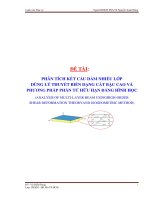
Figure 1.1: Analysis procedure in FEA. Due to the meshing, the computational
domain is only an approximation of the CAD object................................................3
Figure 1.2: Analysis procedure in IGA. No meshing involved, the computational
domain is thus kept exactly........................................................................................4
Figure 2. 1: A quartic B-spline curve...................................................................... 19
Figure 2. 2: The B-spline curve in Figure 2. 1 can be described by three concatenated
Bézier curves. Due to interelement C0 continuity, this representation produces more
control points than the B-spline one........................................................................ 20
Figure 2. 3: An illustration of h-refinement for a B-spline curve...........................23
Figure 2. 4: An illustration of p-refinement for a B-spline curve...........................24
Figure 2. 5: An illustration of k-refinement............................................................ 25
Figure 2. 6: Two representations of the circle. The solid curve is created by NURBS
which describes exactly the circle while the dotted curve is created by B-splines
which is unable to produce an exact circle.............................................................. 27
Figure 2. 7: Two representations of the same circular plate....................................29
Figure 2. 8: A annular plate represented by NURBS surface..................................29
Figure 2. 9: The numerical integration procedure performed in Isogeometric
Analysis approach................................................................................................... 31
Figure 2. 10: Summary of IGA procedure.............................................................. 33
Figure 3. 1. Deformation of transverse normal using CLPT, FSDT and TSDT [13].
41
Figure 3. 2. Distribution function f(z) and its derivation g(z) versus the thickness of
the plates.................................................................................................................. 43
Figure 3. 3. Configuration of a lamina and laminated composite plate...................47
Figure 3. 4. Configuration of a lamina and laminated composite plate...................48
xx
Figure 3. 5. Material and global coordinates of the composite plate.......................49
Figure 3. 6. Configuration of a piezoelectric FG porous plate reinforced by GPLs.
52
53
of the GPLs for each porosity
Figure 3. 7. Porosity distribution types [127],...............................................................................................................................................................................
Figure 3. 8. Three dispersion patterns
and
distribution type [127]............................................................................................. 53
Figure 3.9. Geometry and cross sections of a FGPMP plate made of PZT-4/PZT-5H.
57
Figure 3.10. Variation of elastic coefficient c11 of FGPMP plate made of PZT-4/PZT-
5H with α = 0.2 ...................................................................................................... 59
Figure 4. 1 . A schematic diagram of a laminated plate with integrated piezoelectric
sensors and actuators............................................................................................... 68
Figure 4. 2. Geometry attention of a laminated plate under a sinusoidally distributed
load.......................................................................................................................... 73
Figure 4. 3. Bézier control mesh of a square plate using cubic Bézier elements: (a)
7x7; (b) 11x11 and (c) 15x15................................................................................... 73
Figure 4. 4. Comparison of the normalized stress distributions through the thickness
0
0
0
0
of a four-layer [0 /90 /90 /0 ] laminated composite square plate (a/h = 4).............74
Figure 4. 5. a. Geometry and b. Coarse mesh and control points of a circular plate.
78
Figure 4. 6. A mesh of 11×11 cubic Bézier elements.............................................. 78
0
0
0
0
Figure 4. 7. Six mode shapes of a four-layer [45 /-45 /-45 /45 ] clamped laminated
circular plate with R/h = 5....................................................................................... 83
0
0
0
Figure 4. 8. Central deflection for a [0 /90 /0 ] square laminated plate subjected to
various dynamic loadings........................................................................................ 85
0
0
0
Figure 4. 9. Dimensionless normal stress for a [0 /90 /0 ] square laminated plate
subjected to various dynamic loadings.................................................................... 86
xxi
0
0
0
Figure 4. 10. Central deflection versus time for a [0 /90 /0 ] square laminated plate
subjected to various dynamic loadings.................................................................... 87
0
0
0
Figure 4. 11. Dimensionless normal stress σ xx versus time for a [0 /90 /0 ] square
laminated plate under step loading.......................................................................... 87
Figure 4. 12. Centerline deflection of a simply supported piezoelectric composite
plate subjected uniform load and different input voltages....................................... 91
Figure 4. 13. Effect of actuator input voltages to deflection of the piezoelectric
composite plate [pie/-45/45]as subjected to the uniform loading.............................. 91
Figure 4. 14. The deflection of the piezoelectric composite plates with various
boundary conditions................................................................................................ 92
Figure 4. 15. Geometry and element mesh of a clamped elliptical plate.................92
Figure 4. 16. Six mode shapes of a clamped laminated elliptical plate...................94
Figure 4. 17. Effect of the gain Gd of the displacement feedback control on static
deflections of the SSSS square piezoelectric composite plate with [pie/-45/45]s.....95
Figure 4. 18. Effect of the velocity feedback control gain Gv on the dynamic
deflection response of a CFFF piezoelectric composite plate subjected to a uniform
load.......................................................................................................................... 95
Figure 5. 1. Bézier control mesh of a square sandwich functionally graded porous
plate reinforced by GPL using quadratic Bézier elements.....................................104
Figure 5. 2: Profile of the centerline deflection of square piezoelectric FGM plate
subjected to input voltage of 10V..........................................................................107
Figure 5. 3: Profile of the centerline deflection of square piezoelectric FGM plate
under a uniform loading and different input voltages............................................107
Figure 5. 4: Effect of porosity coefficients and GPL weight fractions on deflection
of PFGP-GPL plates with input voltage of 0V.......................................................110
Figure 5. 5: Profile of the centerline deflection of a cantilever PFGP-GPLs plate with
many kinds of cores under a uniform loading and different input voltages...........111
Figure 5. 6: Time history of load factors...............................................................112
xxii
Figure 5. 7: Transient responses of normalized central deflection of a simply
supported square Al/Al2O3 plate under sinusoidal loading....................................113
Figure 5. 8: Influence of different porosity coefficients to the transient responses of
FGP-GPL plate for porosity distribution 1 and Λ GPL = 0 under various dynamic
loadings.................................................................................................................113
Figure 5. 9: Influence of different porosity coefficients to the transient responses of
FGP-GPL plate for porosity distribution 1, Λ GPL =1wt% and pattern A under various
dynamic loadings...................................................................................................114
Figure 5. 10: Influence of different weight fraction values to the transient responses
of FGP-GPL plate for three GPLs dispersion patterns with uniform porosity
distribution and e0 =0.2 subjected to step loading.................................................115
Figure 5. 11: The profile of the normalized centerline deflection of FGP-GPL plate
with some cases for porosity distribution 1, pattern A under various dynamic
loadings.................................................................................................................116
Figure 5. 12: Effect of different porosity coefficients to the transient responses of
FGP-GPL and PFGP-GPL plate forporosity distribution 1 and Λ GPL = 0 under various
dynamic loadings...................................................................................................117
Figure 5. 13: Effect of different weight fraction values to the transient responses of
FGP-GPL and PFGP-GPL plate for three porosity distributions with pattern A and e0
= 0.2 under sinusoidal loading...............................................................................118
Figure 5. 14: Effect of different weight fraction values to the transient responses of
FGP-GPL and PFGP-GPL plate for three GPLs dispersion patterns with uniform
porosity distribution and e0 = 0.2 under step loading.............................................118
Figure 5. 15: The profile of the normalized centerline deflection of FGP-GPL and
PFGP-GPL plate for some cases with porosity distribution 1, pattern A under the
explosive blast loading..........................................................................................119
Figure 5. 16: Normalized nonlinear transient central deflection of a square
orthotropic plate under the uniform load...............................................................121
xxiii
Figure 5. 17: Centerline linear deflections of the cantilever piezoelectric FG plate
under the uniform loading and various actuator input voltages with n = 0 and n = 0.5.
122
Figure 5. 18: Effect of the material index n on the linear and nonlinear central
deflections of the piezoelectric FG plate under the mechanical load.....................123
Figure 5. 19: Effect of the porosity coefficients on the nonlinear deflection of the
piezoelectric FG porous square plate with GPL dispersion pattern A and
Λ
= 1wt%
........................................................................................................................................................................125
Figure 5. 20: Effect of the weight fractions and dispersion patterns of GPLs on the
GPL
nonlinear deflection of the piezoelectric FG porous square plate with e0 = 0.2.....125
Figure 5. 21: Effect of the porosity coefficients and weight fractions of GPLs on the
nonlinear deflection of piezoelectric FG porous square plate for porosity distribution
1 and different GPL dispersion patterns................................................................126
Figure 5. 22: Effect of the porosity distributions and GPL dispersion patterns on the
nonlinear deflection of the piezoelectric FG porous square plate with e0 = 0.4 and
Λ GPL = 1wt%......................................................................................................126
Figure 5. 23: Effect of the porosity coefficients on the nonlinear dynamic responses
of the CCCC piezoelectric FG porous plate with GPL dispersion pattern A and
Λ GPL = 1wt%....................................................................................... 127
Figure 5. 24: Effect of the weight fractions and dispersion patterns of GPLs on the
nonlinear dynamic responses of the CCCC piezoelectric FG porous square plate with
porosity distribution 2 and e0 = 0.2........................................................................128
Figure 5. 25: Effect of the porosity distributions and GPL dispersion patterns on the
nonlinear dynamic responses of the CCCC piezoelectric FG porous square plate with
129
Figure 5. 26: Linear and nonlinear dynamic responses of the CCCC piezoelectric FG
porous square plate with porosity distribution 2 e0 = 0.3 and dispersion pattern C 129
Figure 5. 27: Effect of the displacement feedback control gain Gd on the linear static
responses of the SSSS plate subjected to uniformly distributed load....................130
xxiv