26 eccentric mechanism kho tài liệu bách khoa
Bạn đang xem bản rút gọn của tài liệu. Xem và tải ngay bản đầy đủ của tài liệu tại đây (3 MB, 67 trang )
ME-430 INTRODUCTION TO COMPUTER AIDED DESIGN
ECCENTRIC MECHANISM OF FOUR-BAR LINKAGE
Pro/ENGINEER Wildfire 2.0
Dr. Herli Surjanhata
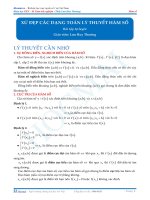
A component can be placed as a connection within mechanism assembly. The
following six joint types are available:
Pin Joint
1
Cylinder Joint
Planar Joint
2
Slider Joint
Ball Joint
3
Bearing Joint
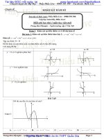
PREPARE THE PARTS FOR MECHANISM
Download the part files eccentric_mechanism.zip. There are eleven parts that
make up the mechanism:
1
2
3
4
5
6
arm.prt
base.prt
bushing.prt
clip-1.prt
clip-2.prt
link.prt
7
8
9
10
11
eccentric.prt
post.prt
shaft.prt
washer-1.prt
washer-2.prt
4
arm.prt
bushing.prt
base.prt
eccentric.prt
5
post.prt
clip-1.prt
shaft.prt
clip-2.prt
6
washer-1.prt
washer-2.prt
link.prt
CREATE AN SUB-ASSEMBLY eccentric_asm.asm
Sub-assembly called eccentric_asm.asm will be consisted of six component parts –
eccentric, shaft, clip-1, clip-2, washer-1, and washer-2.
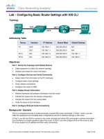
Create a new assembly called ECCENTRIC_ASM
7
Bring in eccentric.prt and constrain
it at default location by picking
.
, then Open
Pick
eccentric.prt.
The assembly is shown below.
Next, place shaft.prt to the assembly. Pick
, then Open shaft.prt.
Pick the axis of the shaft, then select the axis of the center hole of the eccentric.
8
Pick the surfaces as shown below.
9
Mate both surfaces
Be sure to enter 0 when prompted with
offset distance.
to flip the
If necessary, click
orientation of the shaft.
The resulted assembly is shown below.
10
Click
below.
. Then open clip-2.prt. Place clip-2 in the groove of the shaft as shown
Place washer-2.prt right behind clip-2 as shown below.
11
Open clip-1.prt and place it in the groove of the pin of eccentric part – see figure
below.
12
Place washer-1.prt right behind clip-1 – see figure below.
13
The resulted assembly is shown below.
14
Perform Global Interference check of the assembly. Make sure there is no
interference in the assembly.
Analysis -> Model Analysis
Choose Global Interference under
Type.
Click
.
There are NO interference parts in the assembly.
Save the assembly.
15
CREATE AN SUB-ASSEMBLY base_asm.asm
Click
,
Enter the name of base_asm.
OK.
Click
. Then open base.prt and assemble it at default location by selecting
.
16
, and open bushing.prt. Place the bushing at the most left hole in the
Click
base – see figure below.
17
Place again the bushing into the hole located on the right of the base.
Hint: Use Repeat option of the assembly.
Edit -> Repeat etc.
, and open post.prt. Place the post at the most left hole in the base – see
Click
figure below.
18
Perform the Global Interference check and make sure there are NO interference.
19
Save the assembly.
CREATE AN SUB-ASSEMBLY arm_asm.asm
Click
,
Enter the name of arm_asm.
OK.
20
Click
. Then open arm.prt and assemble it at default location by selecting
.
Open clip-1.prt and place it in the groove of the pin of arm part – see figure below.
21
Place washer-1.prt right behind clip-1 – see figure below.
22
The resulted assembly is shown below.
23
CREATE AN TOTAL ASSEMBLY eccentric_mechanism.asm
Click
,
Enter the name of
eccentric_mechanism.
OK.
Click
. Then open sub-assembly base_asm.asm and assemble it at default
location by selecting
.
24
Open sub-assembly eccentric_asm.asm and assemble it at lower right hole in the
base where the bushing is.
, then Open
Pick
eccentric_asm.asm.
Pin connection will be created!
Click the Connect tab for
Connections
Be sure to turn on the datum axis only.
25