toy truck kho tài liệu bách khoa
Bạn đang xem bản rút gọn của tài liệu. Xem và tải ngay bản đầy đủ của tài liệu tại đây (1.57 MB, 52 trang )
TOY TRUCK
Prepared by: Harry Hawkins
The following project is of a small, wooden toy truck. This exercise will provide you with
the procedure for constructing the various parts of the design then assembling them into
the final unit. Directions for creating an album of this project are also included. You will
use a variety of Pro/D tools such as extrude, revolve and others. The orthographic
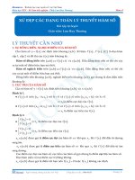
drawing for this project is shown in figure 1.
Figure 1. Orthographic projections of project.
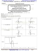
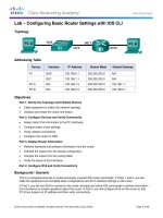
Figure 2 shows the dimensions for the Truck Cab and figure 3 shows the dimensions for
the dump bed. Figure 4 shows the dimensions for the wheels, axel and undercarriage.
These drawings are also located at the end of this tutorial. You will need to refer to them
for accurate numerical information while you construct each part.
0.125
Ø0.5210
0.0730
Headlight
Detail
0.375
0.1875
2.085
4.500
R0.375
All not
marked
1/2 Button
2.500
72°
Ø0.521
2.750
Ø0.375
1.250
0.125
R1.250
2.750
0.750
0.625
0.750
1.500
5.000
Truck Cab
Figure 2. Truck Cab dimensions.
0.750
5.381
0.500
1.500
4.500 4.000
1.500
0.500
1.986
R0.125
0.667
0.750
0.250
Typical
5.631
Dump Bed
39°
5.381
R0.125
0.712
141°
1.064
2.229
2.391
1.165
1.415
1.500
1.500
72°
0.500
0.125
0.375
0.500
Ø0.281
Figure 3. Dump bed dimensions.
© Harry Hawkins 2005
Page 2
Axel (Rear)
4.630
1.500
4.500
Axel (Front)
Ø0.250
R0.125
Ø2.000
9.000
6.500
Ø0.250
0.969
1.500
0.969
1.000
0.500
0.500
0.500
Wheel (6 Req'd)
1.000
Ø0.281
1.000
0.500
3.438
Base Center
Figure 4. Wheels, Axels and Base Center or Undercarriage dimensions.
The procedures for executing the design of each part will be presented separately. Each
step is numbered and they should be done in the order presented. After all parts are
completed, you will proceed to the assembly. Each section is appropriately named and
furnishes appropriate places where breaks may be taken if so desired. The numbers will
continue throughout the tutorial rather than be separate for each part.
© Harry Hawkins 2005
Page 3
AXELS
1. Open a new design and under Tools, select Options and set the Units to inches.
Edit the Workplane notation from initial to Front Axel. Your screen should look like
figure 5.
Figure 5. New design for Front Axel.
2. Draw a 0.25” (1/4”) diameter circle
at the center of the drawing field such as
shown in figure 6. This will be the profile that will be extruded.
Figure 6. Axel profile.
© Harry Hawkins 2005
Page 4
3. Rotate the field so that you can see it in 3D such as figure 7.
Figure 7. Field rotated for 3D viewing.
4. Select the Extrude Profile
button. The extrude profile dialog box will appear.
Edit it according to figure 8. You should see a trial version of the extrusion in yellow.
Press the OK button to execute the extrusion.
Figure 8. Extrude Profile dialog edited for extrusion.
5. Figure 9 is the completed axel. Save this design and name it Front Axel.
Figure 9. Completed Front Axel.
© Harry Hawkins 2005
Page 5
6. Create a new design. Name it Rear Axle. Use the same procedure just completed to
create the rear axle. Notice it is slightly longer than the front. This so the dump bed
will fit properly on the truck. Figure 10 shows the completed rear axle.
Figure 10. Completed rear axle.
© Harry Hawkins 2005
Page 6
BASE (UNDERCARRIAGE)
7. The base unit or undercarriage contains a main strip that runs from the front to the
rear of the vehicle and on which the cab and dump bed are eventually placed. It also
contains the structures that will support the axels and wheels. First start by opening
a new design and editing the initial workplane to base center.
8. Draw a Profile as shown in figure 11. You will need to use the orthographic
drawings to obtain the exact dimensions. Be sure to delete all construction lines so
that the profile will fill with color to indicate a valid profile.
Figure 11. Base Profile ready for extrusion...
9. Rotate the view so you can see it in 3D then select the extrude profile
Edit the dialog box according to figure 12. Press the OK button to execute.
Figure 12. Extrude Profile dialog box and trial view.
© Harry Hawkins 2005
Page 7
button.
10. The extrusion should look like figure 13.
Figure 13. Extruded Base or Undercarriage Strip.
11. We will now extrude or add parts onto the front to extend the housing for the front
wheels. First use the face selection tool to select the top face as shown in figure 14.
The face will turn red.
Figure 14. Face selected for new sketch.
12. With the face selected, right click and select New Sketch. Name it Right Front
Hub. Check create workplane then click the OK button to create the sketch.
13. Click the orthographic view and zoom in on the right front of the object. Construct
the new profile for the hub by drawing over the existing center hub. You will be able
© Harry Hawkins 2005
Page 8
to use the snap points of the center hub to place the lines. Be sure to delete any
unwanted lines. The profile should fill and be ready to extrude such as in figure 15.
Figure 15. Right front hub ready for extrusion.
14. Rotate the view so it will be in 3D then select the Extrude Profile button. Complete
the dialog box to extrude a distance of 0.969”. Press the OK button to execute the
extrusion. It should look like figure 16.
Figure 16. Right front hub extruded. Rotated for clear view.
© Harry Hawkins 2005
Page 9
15. In a similar fashion we will extrude the left front hub. First rotate the object to see the
left face and select it with the select face tool. It will turn red as in figure 17.
Figure 17. Left face selected for left front hub sketch.
16. With the face selected, right click and select New Sketch. Name the sketch Left
Front Hub. Press the OK button to create the sketch plane.
17. Use the view orthographic button to view the sketch.
18. As you did with the right front hub, construct a profile for the left front hub. It
should look like figure 18.
Figure 18. Left front hub profile.
© Harry Hawkins 2005
Page 10
19. Use Extrude Profile to extrude the part a distance of 0.969”. After rotating, it should
look like figure 19. Save this design as the Base Center.
Figure 19. Completed Base Center or Undercarriage.
20. We will now design the wheel. There will be 6 wheels on the finished vehicle, 2 on
the front and 4 on the rear (double on each side). The wheel is relatively easy to
create and will take little time.
© Harry Hawkins 2005
Page 11
WHEEL
21. Open a new design and edit the Initial to wheel.
22. Draw a 2.0” diameter circle at the work center and then a 0.25” diameter circle at
the center of the 2” circle. This should result in a profile such as shown in figure 20.
Figure 20. Wheel profile.
23. Rotate the image so it will be in 3D then select the Extrude Profile button.
Configure the dialog box as shown in figure 21. After configuring, press the OK
button to extrude the profile. Notice the yellow trial visual of the extrusion.
Figure 21. Wheel profile ready to be extruded.
© Harry Hawkins 2005
Page 12
24. Figure 22 shows the resulting extrusion. This view has been rotated to better
visualize the illustration.
Figure 22. Profile after extrusion.
25. Use edge selection
to select the two outside edges of the wheel. Use the
shift key to select more than one edge. The edges will turn red as in figure 23.
Figure 23. Edges of wheel selected for rounding.
26. With the edges selected, right click to see the drop down menu. Select Round
Edges and another dialog box will appear. Edit it according to figure 24 for rounds of
0.13”. Notice that trial rounds will appear in yellow. The wheel is in transparent
mode for better visual effect. Press the OK button to have the rounds completed.
© Harry Hawkins 2005
Page 13
Figure 24. Round Edges dialog box ready for execution.
27. Figure 25 is the wheel after the rounds have been completed. Save this file and
name it Wheel.
Figure 25. Finished Wheel.
© Harry Hawkins 2005
Page 14
CAB
28. Open a new design and name it Cab. Edit initial to cab. Construct the profile shown
in figure 26. We will add the rounds later. Refer to the Truck Cab dimensions to
complete this profile.
Figure 26. Cab profile.
29. To construct the wheel well, delete the bottom 5” cab line then draw a .75” line
from the right end of the nose to the left. Draw another line 2.75” from the left
towards the nose. At the gap between these two lines, construct 3 circles of
R1.25”. Use the snaps to do this. Figure 27 shows the three circles drawn. The top
of the red circle will be the arc. Delete all circle elements except the top arc of the
red circle. The profile should fill with color.
Figure 27. Constructing the wheel well arc using circles.
© Harry Hawkins 2005
Page 15
30. Rotate the image to see it in 3D then select the Extrude Profile button. Edit the
dialog box as shown in figure 28. You will note a yellow trial extrusion.
Figure 28. Cab Extrusion ready to be executed.
31. Press the OK button to execute the extrusion. The result should look like figure 29.
The image has been rotated for a better 3D look.
Figure 29. Completed Cab Profile Extrusion.
32. Use faces selection
to select the front or nose of the cab where the
headlights will be placed. The face will turn red. With the face selected, right click
to show a drop down menu and select New Sketch. Edit the name to Headlight
© Harry Hawkins 2005
Page 16
holes and click the OK box to create the sketch. Figure 30 shows the dialog box
with the selected face in the background.
Figure 30. New Sketch dialog box for the headlight face.
33. Select view orthographic
to display the new sketch face. You may need to
rotate it for better vision.
34. Use lines to locate and place circles of 0.37” diameter at the locations where the
headlights will be located. Figure 31 shows this layout for the left headlight. Be sure
to delete any construction lines so you will have a filled profile.
Figure 31. Layout for left headlight hole.
© Harry Hawkins 2005
Page 17
35. Once the profile of both headlight holes are filled, select the Extrude Profile. Edit
the dialog box as indicated in figure 32. Notice that you will be removing material
below the workplane a distance of 0.13”. Notice the trial visual of the extrusion in
figure 32. Press the OK button to execute.
Figure 32. Headlight holes ready to be extruded.
36. Figure 33 shows the completed headlight holes.
Figure 33. Headlight holes completed by removal extrusion.
© Harry Hawkins 2005
Page 18
37. We will now make the edges of the cab round. All rounds will be 0.38”. The bottom
edges will be left square. Use edge selection to select the edges at the front of the
hood, at the lower end of the windshield and the top front and back of the cab.
Hold down the shift key to select more than one edge. With the edges selected,
right click to see a drop down menu. Select Round Edges. Figure 34 shows the
dialog box and the trial round above it in the background. Click OK to execute the
rounds.
Figure 34. Using the Round Edges feature.
38. In the same manner, select the edges on the left side of the cab as shown on figure
35. Press OK to execute.
Figure 35. Selected left edges for rounding.
© Harry Hawkins 2005
Page 19
39. In a similar fashion select the edges on the right side of the cab and round them to
the same value as previous rounds. The completed cab should look like figure 36.
Save it and give it the name Cab if you have not already done so.
Figure 36. Completed Cab.
© Harry Hawkins 2005
Page 20
HEAD LIGHT
40. The headlight is a simple wooden hole plug. The following procedure is used to
create it. Open a new design and edit initial to headlight.
41. Draw the profile shown in figure 37. This is a half profile. It may be easier to create
the 0.52” circle first then delete line segments to arrive at the arc rather than
drawing the arc from point to point. You can draw a straight line then use the Arc or
Fillet tool
to create the arc.
Figure 37. Full profile before deleting line segments.
42. After deleting unwanted lines, the profile will fill with color as in figure 38.
Figure 38. Half Profile ready for revolution.
© Harry Hawkins 2005
Page 21
43. Click on base in the browser window. The three workplanes will show as glass. The
one on which the profile is contained, in figure 39, has a red perimeter. The other
two will be seen as cross hairs. The one with the red perimeter is selected. This will
be the axis about which the profile will revolve. It must be on the same workplane
as the profile but in a different sketch. Right click and select New Sketch. Edit the
dialog box as in figure 39. Make sure Add to workplane (base) is selected. Press
the OK button to proceed.
Figure 39. New Sketch added to the base workplane.
44. Draw a line over the bottom horizontal line. This will be the axis.
45. Rotate the profile sketch for 3D viewing then select Revolve Profile
. A dialog
box will appear. Edit it to the contents of figure 40. Note that Headlight is the profile
that should show in the box “sketch to use as profile”. If it is not, click on the arrow
at the right of the box and select Headlight. Notice that you will see a yellow trial
view of the revolution. When you have the trial view, click the OK box to finish.
© Harry Hawkins 2005
Page 22
Figure 40. Revolve Profile dialog box edited for revolving the headlight.
46. Figure 41 is a view of the completed headlight part. Name it Headlight and save it
with the other designs in this project.
Figure 41. Completed Headlight.
© Harry Hawkins 2005
Page 23
DUMP BED
47. Start a new design profile. Edit the initial to Dump Bed in the browser. In the
drawing field, construct a profile such as in figure 42. This will be the bottom and
front of the bed. Make sure the profile is “filled” with color to indicate that it is valid.
Refer to the drawings at the end of the tutorial for accurate dimensions.
Figure 42. Profile for Dump bed.
48. Select Extrude Profile
to extrude this profile. Edit the dialog box as in figure
43. You will be adding material a distance of 4.5” below the workplane. Notice you
will see a yellow trial view. Click the OK button to complete the extrusion.
© Harry Hawkins 2005
Page 24
Figure 43. Extrude Profile dialog box with trial view in background.
49. Figure 44 shows the completed extrusion, rotated for a better view.
© Harry Hawkins 2005
Page 25