truc banh rang kho tài liệu bách khoa
Bạn đang xem bản rút gọn của tài liệu. Xem và tải ngay bản đầy đủ của tài liệu tại đây (883.42 KB, 51 trang )
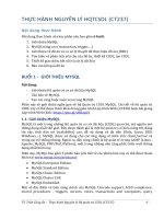
ME-430 INTRODUCTION TO COMPUTER AIDED DESIGN
SHAFT DETAILED DRAWING
Pro/ENGINEER Wildfire 2.0
Dr. Herli Surjanhata
PREPARING THE SHAFT FOR DETAILED DRAWING
Open shaft.prt, and make sure you have the saved view ISO_1.
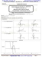
Create A Cosmetic Curve And An Axis Through The Curve Portion Of
The Keyway
From Insert pull down menu, select
Cosmetic -> Sketch
Click Done.
1
Select FRONT as sketching plane, then
click Okay.
Select Top in the SKET VIEW menu,
and pick the TOP datum plane.
Select the curved end of the
sledgerunner keyway as a reference.
Pick this curve
for reference.
2
Sketch a circle as shown.
Click
.
Create An Axis Thru The End Of Keyway
, and pick the curved
Click
end of the sledrunner keyway.
3
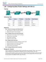
CREATE A DETAILED DRAWING OF THE SHAFT
Select the Create new object icon
Choose Drawing from the New dialog
box. Enter the name shaft.
Uncheck the Use default template.
Click OK button.
Accept SHAFT.PRT as default model,
and click Browse button to pick c.frm
format.
Select Open.
Click OK button.
4
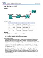
Create FRONT, TOP, RIGHT-SIDE, ISOMETRIC and Detailed views of the shaft
as describe and shown below.
Create The First FRONT View Of The Shaft
Click
shaft.
to insert drawing view of the
The message prompt to Select CENTER POINT fro drawing view, and pick a
location near the middle left of the drawing – see Figure. The Drawing View dialog
box opens.
Under Model view
names, select
FRONT from the
list.
Click OK.
Turn off the
datums and
coordinate system.
,
and click
redraw.
to
Unlock the movement of drawing views.
5
Right-click the graphics
area, and select Lock
View Movement.
Now the view can be
moved
to unlock or
Or click
lock the drawing views.
Create A Projected RIGHT-SIDE View Of The Shaft
Click the FRONT view, then
right-click and select Insert
Projection View.
Pick a location to the right of
the front view.
Create A Projected TOP View Of The Shaft
6
Click the FRONT view, then
right-click and select Insert
Projection View.
Pick a location to the top of the
front view.
Create A Scaled ISOMETRIC View Of The Shaft
to insert
Click
drawing view of the
shaft.
Pick a location near the
upper right-hand corner
of the drawing.
Under Model view
names, select ISO_1
from the list.
Click Apply.
7
Select Scale under
Categories.
Pick Custom Scale.
Enter 0.5 as scale for
view.
Click OK.
Create A Detailed View Of Snap Ring Groove
8
From Insert pull-down menu,
select
Drawing View -> Detailed.
Pick a point on the top view in the center
of the snap ring groove.
Pick a point
here.
The boundary of the detailed view are
defined with a spline. To sketch a spline,
pick points around the center point to
define the view boundary. Press middle
mouse button to finish.
Pick a location above the snap ring
groove on the top view.
The detailed view appears.
Be sure to move the detailed view and
notes to best location – see figure.
9
Define View Display
Define view display to make sure that HIDDEN LINES will be printed for each drawing
views.
•
•
TOP, FRONT & DETAILED views will be displayed with hidden lines.
RIGHT & ISOMETRIC views displayed with no hidden lines.
10
Pick the front, top and
detailed views, make
sure it is boxed in red.
Right-click, and select
Properties.
Un-check Use
present view style.
Select Hidden for
Display style.
OK.
11
Pick the right and
isometric views, make
sure it is boxed in red.
Right-click, and select
Properties.
Select No Hidden for
Display style.
OK.
12
Add Dimensions to the Drawing Views
to open the
Click
Show/Erase dialog box.
Verify that the Show button is selected.
Click the dimension button
.
Select Feature and View in the Show
By section.
From Show pull down menu in the
Navigator, select Model Tree.
13
Pick the revolved protrusion in the Model
Tree or front view.
Click OK.
Click Accept All button to keep all the
dimensions shown.
Zoom into the detailed drawing.
Pick the snap ring groove.
Click OK.
While Sel to Remove button is selected,
pick the 0.60 dimension to remove it.
Click OK.
Pick the keyway and the snap ring groove in the top view, then click OK.
14
Show Axes in the Drawing
Toggle the Dimension button
off and the Axis button
on.
Under Show By, select View.
Pick the front view and click the Accept
All button.
Pick the top view and click the Accept
All button.
Pick the right view and click the Accept
All button.
Pick the detailed view and click the
Accept All button.
Zoom in to the right side view.
Click the Erase button, and Axis button.
Under Erase By, select Selected Items.
Pick the small transverse axis through
the sledrunner keyway to remove it.
15
Show the Surface Finish Symbols
Toggle the Axis icon off and the Surface
Finish icon
on.
Click Show All.
Click Yes.
Erase the Cosmetic Curve from Isometric, Top and Right Side Views
Select Erase, and toggle the Surface
Finish icon off and the Cosmetic icon
on.
Under Erase By, select View, and pick
the isometric view, the top view and the
right side view.
The only cosmetic curve remaining is on
the front view.
Close the Show/Erase dialog box.
16
Clean Up the Drawing Dimensions
Click
.
Pick front, top, and detailed
views.
Click OK.
Accept the default offset and increment
values.
Click Apply.
Click Close.
Switch the Diametral Dimensions to the Top View
Zoom in on the front and top views.
Pick the four diametral dimensions. Right-click, and select Move Item to View.
Pick the top view. The dimensions move.
17
Move the diametral dimensions
underneath the top view.
To move the dimension, click the
dimension, left-click and move the
highlighted dimension to the desired
location.
Right-click and select
Properties.
18
Pick Move Text
button
.
Move the numerical value of the
dimension to the left.
19
Pick the 3.00 keyway length, and move
it to the front view.
Right-click and select Move Item to
View.
Pick the front view.
By default, the movement of
drawing views with the mouse is
disallowed. So, to move the view
, and now the view can
click
be moved to desired location.
Pick the text in the detail note and move
it to the center of detailed view.
20
To move the extension lines, pick the
dimension, then press and hold left
button of the mouse on the extension
line, and move it up.
The result is shown below.
The result after clean up is shown below.
21
Create a Section View for Dimensioning the Keyway Depth and Width
22
Click the front view, then
right-click and choose
Insert Projection View.
Pick a point to the left of
the front view. Turn on
datum plane -
and
.
repaint the screen -
Pick the left view just created, then
right-click and choose Properties.
23
Select Section under
Categories.
Pick 2D Cross-section.
Select Area.
Click
.
Planar -> Single -> Done
Enter A for the cross section name.
Select Make Datum -> Offset
Pick the RIGHT datum plane in
the front view.
OK.
Select Enter Value
Enter a value of -3.5
Select Done
24
Click OK.
Be sure the section view is selected (red
box around it).
Right-click and select Add Arrows.
25