Design and development of oscillating intercultural equipment for rice
Bạn đang xem bản rút gọn của tài liệu. Xem và tải ngay bản đầy đủ của tài liệu tại đây (242.94 KB, 9 trang )
Int.J.Curr.Microbiol.App.Sci (2019) 8(1): 197-205
International Journal of Current Microbiology and Applied Sciences
ISSN: 2319-7706 Volume 8 Number 01 (2019)
Journal homepage:
Original Research Article
/>
Design and Development of Oscillating Intercultural Equipment for Rice
D. Anil Kumar1*, S. Joseph Reddy2, B. Sanjeeva Reddy3,4,
L. Edukondalu1 and V. Srineevasa Rao5
1
NTR College of Agricultural Engineering, ANGRAU, Bapatla– 522 101, India
2
Regional Agricultural Research Station, Nandyal – 518 502, India
3
ICAR - Central Research Institute for Dryland Agriculture, Hyderabad – 500 059, India
4
Institute of Agricultural Engineering & Technology, PJTSAU, Hyderabad – 500 030, India
5
Agricultural College, ANGRAU, BAPATLA – 522 101, India
*Corresponding author
ABSTRACT
Keywords
Design and
Development
Oscillating
Intercultural
Equipment
Article Info
Accepted:
04 December 2018
Available Online:
10 January 2019
Transplanting is the major method of rice cultivation in India. Irrespective of the method
of paddy crop establishment, weed is a major impediment to rice production through its
ability to compete for resources and their impact on paddy crop yields. The cutting tool
will make a reciprocation maximum motion of 6 cm perpendicular to the direction of
transplanted crop rows. This gives an effective working width of 16 cm leaving 7 cm as
root protective zone on either side of the weeded rows. The required stroke lengths
selected for the weeding tool 60, 40 and 20 mm, could be obtained at crank radius of 30,
20 and 10 mm, respectively. The linear speeds of sliding bar for 20, 40 and 60 mm stroke
lengths were observed to be 0.25, 0.51 and 0.76 m s-1, respectively. The peripheral and
angular velocity of crank wheel were 4.97 m s-1 and 39.77 rad s-1, respectively. The force
required to operate the slider bar in the mechanism was 2202.8 N, whereas the force
exerted by the crank wheel to the sliding bar was 2738.08 N. Hence, the design was
satisfactory.
Introduction
Rice (Oryza sativa L.) is India’s prominent
crop, and is the staple food for most of the
Indians. India has the world’s largest area
under rice cultivation and is one of the largest
producers of white rice, accounting for 20 per
cent of global production. The rice production
in India in 2017-18 is 163.516 MT from 43.5
Mha area under rice cultivation (Anonymous,
2018). The proportion of people working in
agricultural sector has decreased and the
consumption demands have increased
gradually. The performance of agricultural
affairs must be improved to have higher
efficiency (Kurstjens, 2007). Transplanting is
the major method of rice cultivation in India.
Irrespective of the method of paddy crop
establishment, weed is a major impediment to
rice production through its ability to compete
197
Int.J.Curr.Microbiol.App.Sci (2019) 8(1): 197-205
for resources and their impact on paddy crop
yields. Under extreme conditions, weeds are
responsible for high yield losses, to the extent
of complete crop loss. Out of the losses due to
various biotic stresses, weeds are known to
account for nearly one third of yield reduction
(Singh et al., 2005; Savary et al., 2005; Rao
and Nagamani, 2007). Thus, weed control is a
major prerequisite for improved rice
productivity and production. Weeds not only
cause huge reductions in rice yields, but also
increase cost of cultivation, reduces input use
efficiency, interfere with other production
operations, impairing quality, act as alternate
hosts for several insect pests, diseases, affect
esthetic look of the ecosystem as well as
native biodiversity and affect human and
livestock health (Rao, 2011).
Effective prevention and control of rice field
weeds is of great significance for improving
rice yield. In recent years, with the expansion
of the production scale of organic rice, there is
an urgent need for an effective physical
weeding control method for rice fields.
Line sowing method of paddy cultivation with
tractor drawn seed-cum-ferti drills or
transplanting of raised paddy nursery in rows
is becoming a common practice in Andhra
Pradesh due to promotion of appropriate
package of machines for paddy cultivation
through state department of Agriculture.
Research work was under taken on selfpropelled intercultural equipment in paddy by
many researchers in USA, Korea, and Japan
and in other countries. In India, though
research was undertaken on manually operated
cone-weeders and power operated selfpropelled weeders, no research work was
reported on tractor operated intercultural
equipment especially in wet land. Keeping
these points in view, a research on design and
development of oscillating weeding machine
for rice was taken up with the following
objectives.
Machine design considerations
Weeding tool design considerations
To develop the weeding tool an effective
width of 10 cm and the maximum working
stroke of 6 cm in design was considered. To
obtain the effective kneading of the wet soil to
uproot the weeds, to the tool base 4 spikes will
be provided at an effective distance of 2.5 cm
centre to centre distance of each spike and two
chain links on extreme edges to bury the
uprooted weeds. The cutting tool will make a
reciprocation maximum motion of 6 cm
perpendicular to the direction of transplanted
crop rows. This gives an effective working
width of 16 cm leaving 7 cm as root protective
zone on either side of the weeded rows. Since,
obtaining oscillation on both on right and left
side from the central position of the tool is a
difficult proposition; it was decided to fix the
tool at the edge of the root protective zone of a
crop row and tool makes reciprocation motion
in the lateral direction. Since, a low horse
power tractor was selected as a power source,
to cover more area in a unit time and utilize
maximum power six similar tools will be
fitted to the main frame of the machine. Based
on these considerations the power requirement
for weeding operation, torque required for the
connecting rod and crank arm etc. were
calculated.
Machine description
The weeding machine basically consists of a
single bar frame with hitch mast, a crank
wheel to provide reciprocate motion, power
transmission system from PTO to the crank
wheel and weeding tools attached to
reciprocating arm. The single bar frame
provides appropriate support and base to fit
the crank wheel and a reciprocating bar. The
rotary power transmission is provided from
PTO to the crank wheel using universal shaft
and a fixed straight shaft rotating with the
support of two pedestal bearings. The crank
198
Int.J.Curr.Microbiol.App.Sci (2019) 8(1): 197-205
wheel is directly fixed to the straight shaft.
The crank wheel in turn is connected to the
reciprocating bar through a connecting rod to
convert rotary motion into reciprocating
motion. The weeding tool tynes are fixed to
the reciprocating bar at set centre to centre
distance to obtain reciprocating motion to
disturb the soil to a depth of 5 cm and uproot
the weeds in operation.
Stroke length in slider crank mechanism
The slider-crank mechanism is used to convert
rotary motion to a reciprocating motion or
vice versa. In the Figure 1, a slider-crank
mechanism was shown and the parameters that
used to define the angles and the link lengths
were presented. As in the case of four-bar
mechanism, the extended and folded dead
centre positions, the crank and the coupler are
collinear (coupler link is commonly called
connecting rod in slider-crank mechanisms).
Full rotation of the crank is possible if the
eccentricity (C) is less than the difference
between the connecting rod (lc) and the crank
length (crank radius ‘r) and the crank length is
less than the connecting rod length (e.g. C<(lcr) and lc>r)
Using the principal of right angled triangles
formed at the dead centre positions
Length of stroke (S), mm = Se – Sf
Length of stroke = Distance of slider travel
between dead centers
If the eccentricity ‘C’ is zero (C=0) the slider
crank mechanism is called an in-line slider
crank and the stroke is twice the crank length
(S=2r). If the eccentricity ‘C’ is not zero
(C≠0), it is usually called an offset slider
crank mechanism. For the present study, an
offset slider crank mechanism was considered.
Geometry representation of slider crank
mechanism was shown in Figure 1.
The speed of oscillation is calculated using an
equation suggested by Celik (2006) as,
Speed of oscillation, m s-1 = (S×N)/30
Where, S = length of stroke, m
N = crank speed, rpm
The velocity of the crank wheel can be
calculated by using equation suggested by
Sharma and Mukesh (2013).
Where, D= Diameter of the crank wheel, m
N= RPM of the crank wheel
Torque and force delivered to oscillating
bar
Similarly,
Where, Se = Horizontal distance between
crank centre to dead centre in fully extended
position of the slider, mm
Sf = Horizontal distance between crank centre
to dead centre in fully folded position of the
slider, mm
C = Clearance between centre line of
oscillating shaft and centre of crank wheel,
mm
The requirement of torque and force to operate
the slider crank mechanism is important in
design of weeding machine and selection of
power source. The slider crank mechanism
consists mainly three parts, namely, crank
wheel, connecting rod and oscillating bar (i.e.
slider). To arrive at the torque and force
requirement, the weights of individual
components were measured and taken into
consideration. The torque and force delivered
to oscillating bar by crank wheel was
calculated using equations suggested by
Ogunlowo and Olaoye (2017).
199
Int.J.Curr.Microbiol.App.Sci (2019) 8(1): 197-205
Where, Tsc = Torque delivered by the crank
wheel, N-m
Psc = Power delivered to the crank wheel, HP
Nsc = Speed of the crank wheel, RPM
Where, Fs = Static force, N
FC = Total force coming on to the weeding
tools due soil cutting, N
FN = Normal force, N
mt = Total mass, the oscillating bar and
working tools, kg
g = Acceleration due to gravity, 9.81 m s-2
= coefficient of static friction, 0.74 for steel
on steel
Materials and Methods
The machine mainly consisted of the
following components, main frame with three
point hitch system, slider crank mechanism
(crank wheel, connecting rod and oscillating
shaft), working tools and chain links.
Main frame with three point hitch system
A 22 HP 4 WD tractor was used as power
source to operate the intercultural equipment
in rice field. The main frame of the machine
was fabricated as a single bar frame using a
75X65 mm size M S U- channel having a
thickness of 7 mm. The frame length was
2500 mm to support the slider and crank
mechanism. Main frame was provided a three
point hitch mast on the flat side of the channel.
Three point hitch mast was fabricated using a
65 mm width mild steel flat with 10 mm
thickness and fitted to two U channel pieces (5
mm thickness, 40 mm width and 75 mm
height)provided as an extension bar from the
main frame. These two extended channel
pieces were connected together using another
cross channel material piece to give enough
support for the frame and the hitch mast.
Slider crank mechanism
Slider crank mechanism was designed to
convert rotary motion to reciprocating motion.
The rotary motion of the PTO shaft
transmitted to the slider crank mechanism
through the universal joint and a shaft. Slider
crank mechanism consists of crank wheel,
connecting rod and oscillating shaft.
Fabrication details of each component in slider
crank mechanism were explained in detailed
below.
Oscillating bar
The length of oscillating bar was fabricated
based on the row to row spacing of rice crop.
In general, row to row spacing in paddy
ranges from 25 to 30 cm. For design
calculation in the present case, weeding
operation in six rows simultaneously was
considered and the length of reciprocating bar
was kept as 230 cm.
Two 50×50×6 mm size of L-angle bars were
taken and jointed using weld joints to make a
hollow square bar to use as a oscillating bar. It
is in a square shape, and fits into the U-shaped
main frame. Two roller bearings were fitted
inside the L-angle square bar on either side at
a center to center distance of 1800 mm. The
bearings works smoothly just like a solid
metal rollers in the U-channel in which the bar
moves sideways from left to right or vice
versa. Oscillating bar gets the motion from
crank wheel through connecting rod (Fig. 2).
Crank shaft and crank wheel
A720 mm length and 37 mm diameter mild
steel solid rod was taken and turned to 35 mm
200
Int.J.Curr.Microbiol.App.Sci (2019) 8(1): 197-205
diameter and both ends faces were finished. At
one end of the finished shaft, splines were cut
just like the PTO shaft splines and at another
end 60x3 mm key way groove was made. The
shaft thus prepared was fitted on the main
frame with the help of two support bars using
pedestal bearings of 35 mm size to give free
rotation to the shaft.
A metal plate of 10 mm thickness was taken
and 270 mm circular flange piece was
separated using a gas cutter and the cut piece
was smoothly turned to a diameter of 250
mm.A mild steel solid rod of 50x55 mm was
taken and turned to smooth surface on the
periphery and a 35 mm bore was drilled.
holes were drilled over a length of 240 mm
keeping center to center distance 60 mm apart.
Six pieces of 100 mm length and 18x18 mm
size solid metal pieces were taken and four
numbers of spikes of 50 mm length and 10x10
mm size were welded at one face to work as a
soil disturbing tool. These tools were fitted to
the lower end of the tyne using nu and bolt
keeping upright down the metal spikes.
Chain links
A rectangular solid cross-section 25x25 mm
size rod was used as a connecting rod. One
end of connecting rod was positioned at
certain position on crank wheel slot and other
end is connected to the oscillating shaft using
a. The position of connecting rod on crank
wheel will decide the stroke length.
While in weed removal practice under wet
land conditions it is impossible to visualize
weather all weeds are physically removed or
not. So, it is a common practice to trample the
weed biomass to bury into the soil. So, to
achieve the same objective chain links two in
number were attached to the tool. When the
tool oscillates in between the crop rows chain
links will move in a zig-zag path dragging the
disturbed soil to cover the weed biomass.
Three different lengths (50, 100 and 150 mm)
and thicknesses(3, 5 and 7 mm) chain links
were selected for the study and used in the
field condition.
Tynes
Results and Discussion
As the bar oscillates correspondingly the tools
also oscillates disturbing the soil which in turn
aid in disturbing and uprooting the weeds
from the soil. The length of the tyne required
to the tool will be varied according to the
ground clearance of the tractor and sinkage of
the tyres depending upon the field conditions.
A 100 mm length, 40x4 mm size mild steel Langle pieces were taken and 10 mm diameter
holes two in number were drilled keeping 60
mm hole to hole center distance by matching
two pieces together. The matched pair of cut
pieces was welded on outer side of oscillating
bar keeping face to face at 26 mm apart. These
welded L-angle pieces work as a brackets to
help in fixing the working tool tynes. To
adjust the length of tynes 10 mm diameter
To obtain the desired oscillation motion for
the working tool, the stroke length of
oscillating bar needs to be calculated. The
stroke length will depend on the length of
connecting rod and the crank wheel slider bar.
The required stroke lengths can be achieved
by changing the position of connecting rod
(i.e. crank radius) on the crank wheel slot. The
tyne has to make an oscillatory maximum
motion of 60 mm perpendicular to the
direction of travel. As a result the weeding
tool will get an effective working width of 160
mm leaving 70 mm as root protective zone on
either side of the weeded rows. Accordingly,
different crank wheel radius positions were
selected for a fixed connecting rod length of
700 mm and stroke lengths were calculated
Connecting rod
201
Int.J.Curr.Microbiol.App.Sci (2019) 8(1): 197-205
without changing the eccentricity value (Table
1).
It was observed that the crank position and
moment and the stroke length were linearly
related with a constant multiplication factor
(S=2r). The data presented in Figure 3
indicates that without changing the connecting
rod and eccentricity values one can obtain the
required stroke lengths for the oscillating tool,
if the boundary conditions are set within the
required limits the required stroke lengths
selected for the weeding tool 60, 40 and 20
mm, could be obtained at crank radius of 30,
20 and 10 mm, respectively. This fact was also
verified by constraining the crank arm to these
limits in the machine and the stroke lengths
were found very well within the limits. These
limits were noted and marked on the sliding
bar in further experimental works.
Motionvelocities of sliding bar and crank
wheel
The tractor engine was operated at 1500 RPM
and at this particular point PTO shaft rotates at
380 RPM and was measured using a
mechanical tachometer.
The calculated velocities of sliding bar and
crank wheel were given in Table 2. It was
observed that the linear speed of sliding bar
increased with increase of stroke length. The
linear speeds of sliding bar for 20, 40 and 60
mm stroke lengths were observed to be 0.25,
0.51 and 0.76 m s-1, respectively. The crank
wheel peripheral and angular velocities were
remained constant. The peripheral and angular
velocity of crank wheel were 4.97 m s-1 and
39.77 rad s-1, respectively.
since the PTO shaft was connected to the
crank wheel shaft directly. As per the design
considerations, no reduction of power from
the PTO shaft to crank wheel shaft was set.
The power delivered from the PTO shaft to the
crank wheel through the shaft was taken as
13.62 kW. So, the power delivered to the
slider crank remains same (13.62 kW) since,
there was no power reduction gear box. The
revolutions of the crank wheel were observed
as 380 rpm. The torque delivered by the crank
wheel to the sliding bar was calculated using
the equation
The torque transmitted by crank wheel was
calculated as 342.26 N-m.
The force acting on the crank wheel = Torque
on crank wheel / radius of crank wheel
= 342.26 / 0.125 = 2738.08 N.
The soil cutting force encountered by the
machine was calculated taking the soil cutting
resistance (0.5 kgf cm-2 Mahilang et al., 2017)
and effective soil cutting cross sectional area
by the tool.
The effective cutting cross sectional area of
soil by the individual tool when oscillating bar
moves 6 cm length was 13.5 cm and depth of
soil cutting was considered as 5 cm.
Torque and force delivered to oscillating
bar
The cutting force of soil acting on each tool =
13.5×5×0.5 = 33.75 kg
The torque delivered by the PTO shaft was
342.26 N-m. The crank wheel rotates at the
same rotational speed as that of PTO speed,
The total cutting force acting on six number of
tools = 33.75× 9.8 × 6 = 1984.5 N
202
Int.J.Curr.Microbiol.App.Sci (2019) 8(1): 197-205
The weight of the sliding bar (mt) including
acceleration due to gravity as (9.81 m s-2).
The normal force (N) of the sliding bar was
calculated using equation
working tools was calculated as 30 kg and
= 217.78 N
Now, total force acting on the sliding bar
294.3 N
As per the soil resistance point of view, the
total force (2202.8 N) acting on the sliding
bar through soil cutting action found to be
less than the force (2738.08 N) exerted by the
crank wheel to the sliding bar. Hence, the
design was satisfactory with the set
parameters.
The oscillating bar oscillates sideways on Uchannel steel frame with the force of
connecting rod. The coefficient of static
friction for steel on steel was taken as 0.74
and normal force of the oscillating bar was
294.3 N.
Table 1 Different stroke lengths for different crank positions
Clearance, C,
mm
Crank radius, r,
mm
Connecting rod
length, Lc, mm
Stroke Length, mm
S= Se - Sf
25
10
700
20
25
20
700
40
25
30
700
60
25
40
700
80
25
50
700
100
Table.2 Motions of sliding bar and crank wheel
Stroke
Length, mm
20
40
60
Linear speed of
sliding bar,
m s-1
0.25
0.51
0.76
Crank wheel
peripheral velocity,
m s-1
4.97
203
Crank wheel
angular velocity,
rad s-1
39.77
Int.J.Curr.Microbiol.App.Sci (2019) 8(1): 197-205
Fig.1 Geometry representation of slider crank mechanism
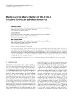
Fig.2 Isometric view of developed oscillating intercultural equipment
Three point hitch
Pedestal bearings
Crank Wheel
Shaft
Tyne
Main frame
Chain links
Connecting rod
204
Oscillating shaft
Int.J.Curr.Microbiol.App.Sci (2019) 8(1): 197-205
Fig.3 Effect of connecting rod length on stroke lengths at different crank positions
In conclusions the required stroke lengths
selected for the weeding tool 60, 40 and 20
mm, could be obtained at crank radius of 30,
20 and 10 mm, respectively. The linear
speeds of sliding bar for 20, 40 and 60 mm
stroke lengths were observed to be 0.25,
0.51 and 0.76 m s-1, respectively. The
peripheral and angular velocity of crank
wheel were 4.97 m s-1 and 39.77 rad s-1,
respectively. The force required to operate
the slider bar in the mechanism was 2202.8
N, whereas the force exerted by the crank
wheel to the sliding bar was 2738.08 N.
Hence, the design was satisfactory.
Engineering. 48: 223-227.
Ogunlowo, Q.O and Olaoye, J.O. 2017.
Development
and
performance
evaluation of a guided horizontal
conveyor rice harvester. Agrosearch.
17(1): 66–88.
Rao, A.N. 2011. Integrated weed
management in rice in India.
/>tion/216018976.
Savary, S., Castilla, N.P., Elazegui, F.A and
Teng, P.S. 2005. Multiple effects of
two drivers of agricultural change,
labor shortage and water scarcity, on
rice pest profiles in tropical Asia.
Field Crops Research. 91: 263-271.
Singh, S., Singh, G., Singh, V. P. and Singh,
A. P. 2005. Effect of establishment
methods and weed management
practices on weeds and rice in ricewheat cropping system. Indian
Journal of Weed Science. 37: 51-57.
References
Anonymous. 2018. International Rice
Research
Institute.
:8080/wrs.
Celik, A. 2006. Design and operating
characteristics of a push type cutter
bar mower. Canadian Biosystems
How to cite this article:
Anil Kumar, D., S. Joseph Reddy, B. Sanjeeva Reddy, L. Edukondalu and Srineevasa Rao, V.
2019. Design and Development of Oscillating Intercultural Equipment for Rice.
Int.J.Curr.Microbiol.App.Sci. 8(01): 197-205. doi: />
205