Lecture Mechanics of materials (Third edition) - Chapter 1: Introduction - Concept of stress
Bạn đang xem bản rút gọn của tài liệu. Xem và tải ngay bản đầy đủ của tài liệu tại đây (1.7 MB, 25 trang )
Third Edition
CHAPTER
MECHANICS OF
MATERIALS
Ferdinand P. Beer
E. Russell Johnston, Jr.
John T. DeWolf
Introduction –
Concept of Stress
Lecture Notes:
J. Walt Oler
Texas Tech University
© 2002 The McGraw-Hill Companies, Inc. All rights reserved.
Third
Edition
MECHANICS OF MATERIALS
Beer • Johnston • DeWolf
Contents
Concept of Stress
Bearing Stress in Connections
Review of Statics
Stress Analysis & Design Example
Structure Free-Body Diagram
Rod & Boom Normal Stresses
Component Free-Body Diagram
Pin Shearing Stresses
Method of Joints
Pin Bearing Stresses
Stress Analysis
Stress in Two Force Members
Design
Stress on an Oblique Plane
Axial Loading: Normal Stress
Maximum Stresses
Centric & Eccentric Loading
Stress Under General Loadings
Shearing Stress
State of Stress
Shearing Stress Examples
Factor of Safety
© 2002 The McGraw-Hill Companies, Inc. All rights reserved.
1-2
Third
Edition
MECHANICS OF MATERIALS
Beer • Johnston • DeWolf
Concept of Stress
• The main objective of the study of mechanics
of materials is to provide the future engineer
with the means of analyzing and designing
various machines and load bearing structures.
• Both the analysis and design of a given
structure involve the determination of stresses
and deformations. This chapter is devoted to
the concept of stress.
© 2002 The McGraw-Hill Companies, Inc. All rights reserved.
1-3
Third
Edition
MECHANICS OF MATERIALS
Beer • Johnston • DeWolf
Review of Statics
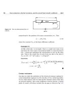
• The structure is designed to
support a 30 kN load
• The structure consists of a
boom and rod joined by pins
(zero moment connections) at
the junctions and supports
• Perform a static analysis to
determine the internal force in
each structural member and the
reaction forces at the supports
© 2002 The McGraw-Hill Companies, Inc. All rights reserved.
1-4
Third
Edition
MECHANICS OF MATERIALS
Beer • Johnston • DeWolf
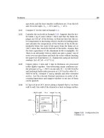
Structure Free-Body Diagram
• Structure is detached from supports and
the loads and reaction forces are indicated
• Conditions for static equilibrium:
∑ M C = 0 = Ax (0.6 m ) − (30 kN )(0.8 m )
Ax = 40 kN
∑ Fx = 0 =Ax + C x
C x = − Ax = −40 kN
∑ Fy = 0 = Ay + C y − 30 kN = 0
Ay + C y = 30 kN
• Ay and Cy can not be determined from
these equations
© 2002 The McGraw-Hill Companies, Inc. All rights reserved.
1-5
Third
Edition
MECHANICS OF MATERIALS
Beer • Johnston • DeWolf
Component Free-Body Diagram
• In addition to the complete structure, each
component must satisfy the conditions for
static equilibrium
• Consider a free-body diagram for the boom:
∑ M B = 0 = − Ay (0.8 m )
Ay = 0
substitute into the structure equilibrium
equation
C y = 30 kN
• Results:
A = 40 kN → C x = 40 kN ← C y = 30 kN ↑
Reaction forces are directed along boom
and rod
© 2002 The McGraw-Hill Companies, Inc. All rights reserved.
1-6
Third
Edition
MECHANICS OF MATERIALS
Beer • Johnston • DeWolf
Method of Joints
• The boom and rod are 2-force members, i.e.,
the members are subjected to only two forces
which are applied at member ends
• For equilibrium, the forces must be parallel to
to an axis between the force application points,
equal in magnitude, and in opposite directions
• Joints must satisfy the conditions for static
equilibrium which may be expressed in the
form of a force triangle:
G
F
∑ B =0
FAB FBC 30 kN
=
=
4
5
3
FAB = 40 kN
© 2002 The McGraw-Hill Companies, Inc. All rights reserved.
FBC = 50 kN
1-7
Third
Edition
MECHANICS OF MATERIALS
Beer • Johnston • DeWolf
Stress Analysis
Can the structure safely support the 30 kN
load?
• From a statics analysis
FAB = 40 kN (compression)
FBC = 50 kN (tension)
• At any section through member BC, the
internal force is 50 kN with a force intensity
or stress of
dBC = 20 mm
50 × 103 N
P
σ BC = =
= 159 MPa
A 314 × 10-6 m 2
• From the material properties for steel, the
allowable stress is
σ all = 165 MPa
• Conclusion: the strength of member BC is
adequate
© 2002 The McGraw-Hill Companies, Inc. All rights reserved.
1-8
Third
Edition
MECHANICS OF MATERIALS
Beer • Johnston • DeWolf
Design
• Design of new structures requires selection of
appropriate materials and component dimensions
to meet performance requirements
• For reasons based on cost, weight, availability,
etc., the choice is made to construct the rod from
aluminum (σall= 100 MPa). What is an
appropriate choice for the rod diameter?
P
σ all =
A
A=
d2
A=π
4
d=
4A
π
=
(
P
σ all
=
50 × 103 N
100 × 106 Pa
4 500 × 10− 6 m 2
π
= 500 × 10− 6 m 2
) = 2.52 ×10⁻² m = 25.2 mm
• An aluminum rod 26 mm or more in diameter is
adequate
© 2002 The McGraw-Hill Companies, Inc. All rights reserved.
1-9
Third
Edition
MECHANICS OF MATERIALS
Beer • Johnston • DeWolf
Axial Loading: Normal Stress
• The resultant of the internal forces for an axially
loaded member is normal to a section cut
perpendicular to the member axis.
• The force intensity on that section is defined as
the normal stress.
∆F
∆A→0 ∆A
σ = lim
σ ave =
P
A
• The normal stress at a particular point may not be
equal to the average stress but the resultant of the
stress distribution must satisfy
P = σ ave A = ∫ dF = ∫ σ dA
A
• The detailed distribution of stress is statically
indeterminate, i.e., can not be found from statics
alone.
© 2002 The McGraw-Hill Companies, Inc. All rights reserved.
1 - 10
Third
Edition
MECHANICS OF MATERIALS
Beer • Johnston • DeWolf
Centric & Eccentric Loading
• A uniform distribution of stress in a section
infers that the line of action for the resultant of
the internal forces passes through the centroid
of the section.
• A uniform distribution of stress is only
possible if the concentrated loads on the end
sections of two-force members are applied at
the section centroids. This is referred to as
centric loading.
• If a two-force member is eccentrically loaded,
then the resultant of the stress distribution in a
section must yield an axial force and a
moment.
• The stress distributions in eccentrically loaded
members cannot be uniform or symmetric.
© 2002 The McGraw-Hill Companies, Inc. All rights reserved.
1 - 11
Third
Edition
MECHANICS OF MATERIALS
Beer • Johnston • DeWolf
Shearing Stress
• Forces P and P’ are applied transversely to the
member AB.
• Corresponding internal forces act in the plane
of section C and are called shearing forces.
• The resultant of the internal shear force
distribution is defined as the shear of the section
and is equal to the load P.
• The corresponding average shear stress is,
τ ave =
P
A
• Shear stress distribution varies from zero at the
member surfaces to maximum values that may be
much larger than the average value.
• The shear stress distribution cannot be assumed to
be uniform.
© 2002 The McGraw-Hill Companies, Inc. All rights reserved.
1 - 12
Third
Edition
MECHANICS OF MATERIALS
Beer • Johnston • DeWolf
Shearing Stress Examples
Single Shear
τ ave =
P F
=
A A
© 2002 The McGraw-Hill Companies, Inc. All rights reserved.
Double Shear
τ ave =
P F
=
A 2A
1 - 13
Third
Edition
MECHANICS OF MATERIALS
Beer • Johnston • DeWolf
Bearing Stress in Connections
• Bolts, rivets, and pins create
stresses on the points of contact
or bearing surfaces of the
members they connect.
• The resultant of the force
distribution on the surface is
equal and opposite to the force
exerted on the pin.
• Corresponding average force
intensity is called the bearing
stress,
σb =
© 2002 The McGraw-Hill Companies, Inc. All rights reserved.
P P
=
A td
1 - 14
Third
Edition
MECHANICS OF MATERIALS
Beer • Johnston • DeWolf
Stress Analysis & Design Example
• Would like to determine the
stresses in the members and
connections of the structure
shown.
• From a statics analysis:
FAB = 40 kN (compression)
FBC = 50 kN (tension)
• Must consider maximum
normal stresses in AB and
BC, and the shearing stress
and bearing stress at each
pinned connection
© 2002 The McGraw-Hill Companies, Inc. All rights reserved.
1 - 15
Third
Edition
MECHANICS OF MATERIALS
Beer • Johnston • DeWolf
Rod & Boom Normal Stresses
• The rod is in tension with an axial force of 50 kN.
• At the rod center, the average normal stress in the
circular cross-section (A = 314x10-6m2) is σBC = +159
MPa.
• At the flattened rod ends, the smallest cross-sectional
area occurs at the pin centerline,
A = (20 mm )(40 mm − 25 mm ) = 300 × 10− 6 m 2
50 × 103 N
P
σ BC ,end = =
= 167 MPa
A 300 × 10− 6 m 2
• The boom is in compression with an axial force of 40
kN and average normal stress of –26.7 MPa.
• The minimum area sections at the boom ends are
unstressed since the boom is in compression.
© 2002 The McGraw-Hill Companies, Inc. All rights reserved.
1 - 16
Third
Edition
MECHANICS OF MATERIALS
Beer • Johnston • DeWolf
Pin Shearing Stresses
• The cross-sectional area for pins at A, B,
and C,
2
⎛ 25 mm ⎞
−6 2
A = πr = π⎜
⎟ = 491× 10 m
⎝ 2 ⎠
2
• The force on the pin at C is equal to the
force exerted by the rod BC,
P
50 × 103 N
τ C , ave = =
= 102 MPa
A 491× 10− 6 m 2
• The pin at A is in double shear with a
total force equal to the force exerted by
the boom AB,
τ A, ave =
© 2002 The McGraw-Hill Companies, Inc. All rights reserved.
P
20 kN
=
= 40.7 MPa
A 491× 10− 6 m 2
1 - 17
Third
Edition
MECHANICS OF MATERIALS
Beer • Johnston • DeWolf
Pin Shearing Stresses
• Divide the pin at B into sections to determine
the section with the largest shear force,
PE = 15 kN
PG = 25 kN (largest)
• Evaluate the corresponding average
shearing stress,
τ B, ave =
© 2002 The McGraw-Hill Companies, Inc. All rights reserved.
PG
25 kN
=
= 50.9 MPa
A 491× 10− 6 m 2
1 - 18
Third
Edition
MECHANICS OF MATERIALS
Beer • Johnston • DeWolf
Pin Bearing Stresses
• To determine the bearing stress at A in the boom AB,
we have t = 30 mm and d = 25 mm,
σb =
P
40 kN
=
= 53.3 MPa
td (30 mm )(25 mm )
• To determine the bearing stress at A in the bracket,
we have t = 2(25 mm) = 50 mm and d = 25 mm,
σb =
P
40 kN
=
= 32.0 MPa
td (50 mm )(25 mm )
© 2002 The McGraw-Hill Companies, Inc. All rights reserved.
1 - 19
Third
Edition
MECHANICS OF MATERIALS
Beer • Johnston • DeWolf
Stress in Two Force Members
• Axial forces on a two force
member result in only normal
stresses on a plane cut
perpendicular to the member axis.
• Transverse forces on bolts and
pins result in only shear stresses
on the plane perpendicular to bolt
or pin axis.
• Will show that either axial or
transverse forces may produce both
normal and shear stresses with respect
to a plane other than one cut
perpendicular to the member axis.
© 2002 The McGraw-Hill Companies, Inc. All rights reserved.
1 - 20
Third
Edition
MECHANICS OF MATERIALS
Beer • Johnston • DeWolf
Stress on an Oblique Plane
• Pass a section through the member forming
an angle θ with the normal plane.
• From equilibrium conditions, the
distributed forces (stresses) on the plane
must be equivalent to the force P.
• Resolve P into components normal and
tangential to the oblique section,
F = P cosθ
V = P sin θ
• The average normal and shear stresses on
the oblique plane are
σ=
τ=
© 2002 The McGraw-Hill Companies, Inc. All rights reserved.
F
P cosθ
P
cos 2 θ
=
=
Aθ A0
A0
cosθ
V
P sin θ
P
=
=
sin θ cosθ
Aθ A0
A0
cosθ
1 - 21
Third
Edition
MECHANICS OF MATERIALS
Beer • Johnston • DeWolf
Maximum Stresses
• Normal and shearing stresses on an oblique
plane
σ=
P
cos 2 θ
A0
τ=
P
sin θ cosθ
A0
• The maximum normal stress occurs when the
reference plane is perpendicular to the member
axis,
σm =
P
A0
τ′ = 0
• The maximum shear stress occurs for a plane at
+ 45o with respect to the axis,
τm =
© 2002 The McGraw-Hill Companies, Inc. All rights reserved.
P
P
sin 45 cos 45 =
=σ′
A0
2 A0
1 - 22
Third
Edition
MECHANICS OF MATERIALS
Beer • Johnston • DeWolf
Stress Under General Loadings
• A member subjected to a general
combination of loads is cut into
two segments by a plane passing
through Q
• The distribution of internal stress
components may be defined as,
∆F x
σ x = lim
∆A→0 ∆A
τ xy = lim
∆A→0
∆V yx
∆A
∆Vzx
τ xz = lim
∆A→0 ∆A
• For equilibrium, an equal and
opposite internal force and stress
distribution must be exerted on
the other segment of the member.
© 2002 The McGraw-Hill Companies, Inc. All rights reserved.
1 - 23
Third
Edition
MECHANICS OF MATERIALS
Beer • Johnston • DeWolf
State of Stress
• Stress components are defined for the planes
cut parallel to the x, y and z axes. For
equilibrium, equal and opposite stresses are
exerted on the hidden planes.
• The combination of forces generated by the
stresses must satisfy the conditions for
equilibrium:
∑ Fx = ∑ Fy = ∑ Fz = 0
∑Mx = ∑My = ∑Mz = 0
• Consider the moments about the z axis:
∑ M z = 0 = (τ xy ∆A)a − (τ yx ∆A)a
τ xy = τ yx
similarly, τ yz = τ zy
and τ yz = τ zy
• It follows that only 6 components of stress are
required to define the complete state of stress
© 2002 The McGraw-Hill Companies, Inc. All rights reserved.
1 - 24
Third
Edition
MECHANICS OF MATERIALS
Beer • Johnston • DeWolf
Factor of Safety
Structural members or machines
must be designed such that the
working stresses are less than the
ultimate strength of the material.
FS = Factor of safety
FS =
σu
ultimate stress
=
σ all allowable stress
Factor of safety considerations:
• uncertainty in material properties
• uncertainty of loadings
• uncertainty of analyses
• number of loading cycles
• types of failure
• maintenance requirements and
deterioration effects
• importance of member to structures
integrity
• risk to life and property
• influence on machine function
© 2002 The McGraw-Hill Companies, Inc. All rights reserved.
1 - 25