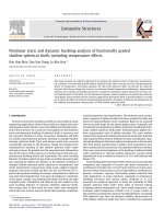
Extended radial point interpolation method for dynamic crack analysis in functionally graded materials
Bạn đang xem bản rút gọn của tài liệu. Xem và tải ngay bản đầy đủ của tài liệu tại đây (456.41 KB, 8 trang )
TAẽP CH PHAT TRIEN KH&CN, TAP 18, SO K4- 2015
Extended radial point interpolation method
for dynamic crack analysis in functionally
graded materials
Nguyen Thanh Nha
Tran Kim Bang
Bui Quoc Tinh
Truong Tich Thien
Ho Chi Minh city University of Technology, VNU-HCM
(Manuscript Received on August 01st, 2015, Manuscript Revised August 27th, 2015)
ABSTRACT:
Functionally
graded
materials
(FGMs) have been widely used as
advanced materials characterized by
variation in properties as the dimension
varies. Studies on their physical
responses under in-serve or external
loading conditions are necessary.
Especially, crack behavior analysis for
these advanced material is one of the
most essential in engineering. In this
present, an extended meshfree radial
point interpolation method (RPIM) is
applied for calculating static and dynamic
stress intensity factors (SIFs) in
functionally graded materials. Typical
advantages of RPIM shape function are
the satisfactions of the Kroneckers delta
property and the high-order continuity.
To assess the static and dynamic stress
intensity factors, non-homogeneous form
of interaction integral with the nonhomogeneous asymptotic near crack tip
fields is used. Several benchmark
examples in 2D crack problem are
performed such as static and dynamic
crack parameters calculation. The
obtained results are compared with other
existing solutions to illustrate the
correction of the presented approach.
Key words: FGMs, crack, stress intensity factors, meshless, RPIM
1. INTRO DUCTIO N
Functionally graded materials (FGMs) are
types of advanced composite that have been made
based on the concept of continuous variation of
microstructures. The non-uniform distributions of
the reinforcement phase cause different material
properties in one or more specified directions [1,
2]. In recent years, the FGMs hold promising for
applications that require extra high material
performance [3]. For example, FGMs are used in
thermal protection systems because they evolve
the advantage of typical ceramics such as heat
and corrosion resistance and typical of metal such
as stiffness and mechanical strength. FGMs can
be applied to generate thermal barrier coating for
space
applications,
thermal-electric
and
piezoelectric devices, optical materials with
graded reflective indices, bone and dental
implants in medicine and so on. In many cases,
FGMs structure are brittle and prone to cracking
due to hard working conditions such as overload,
Page 59
SCIENCE & TECHNOLOGY DEVELOPMENT, Vol 18, No.K4- 2015
vibration, fatigue, and so on. For the reason that,
crack behaviors of such FGMs has become an
interesting study subject.
In this work, we focus on fracture behaviors
of FGMs under static and dynamic loading. There
are several analytical and also numerical studies
that have been performed to obtain the fracture
behavior of FGMs structures. Delale and Erdogan
et al considered the stress field at crack tip in
FGM which has the same square root singularity
as that in the homogenous materials [4]. In 1987,
Eischen et al present his mixed-mode crack
analysis in non-homogenous materials using
finite element method (FEM) [5]. Gu P. et al
(1999) used domain J-integral to calculate the
crack tip field of FGM [6]. In 2002, Kim and
Paulino used FEM to calculate the mixed-mode
SIFs in FGMs with some modifies for pathindependent integral [7]. In 2005, Menouillard et
al applied extended finite element method
(XFEM) to calculate mixed-mode stress intensity
factors for graded materials [8]. In the next year,
Song et al applied FEM to compute the dynamic
SIFs for heterogeneous materials [9]. In 2007,
Kim and Paulino performed crack propagation
problems in FGMs using XFEM [10]. Recently,
in the last year, Chiong et at presented the scaled
boundary FEM using polygon element for
dynamic SIFs calculation for FGMs [11].
Over the ensuing decades, the so-called
meshless or meshfree methods have developed.
Different from FEM, meshfree methods do not
require a mesh connect data points of the
simulation domain. Since no finite mesh is
required in the approximation, meshfree methods
are very suitable for modeling crack growth
problems [12, 13, 14, 15]. There are a few studies
about meshless method for fracture problems in
FGMs in recent years. Rao and Rahman (2003)
Page 60
used EFG method for calculating SIFs in
isotropic FGMs [16]. In 2006, Sladek et al
applied meshless local Petrov-Galerkin method to
evaluate fracture parameters for crack problems
in FGM [17]. In 2009, Koohkan et al presented a
new technique with J-integral to calculate the SIF
values for FGM crack problems [18].
In this study, we propose an extended
meshfree method based on the radial point
interpolation method (XRPIM) associated with
the vector level set method for modeling the
crack problem in functionally graded materials
under static and dynamic loading conditions. To
calculate the SIFs, the dynamic form of
interaction
integral
formulation
for
nonhomogeneous materials is used. Several
numerical examples including static and dynamic
SIFs calculation are performed and investigated
to highlight the accuracy of the proposed method.
2. XRPIM FO RM ULATION
CRACK PROBLEMS
FO R
2.1. Weak-form formulation
Consider a 2D solid with domain and
bounded by , the initial crack face is denoted
by boundary C , the body is subjected to a body
force b and traction t on t as depicted in Fig.
1. The weak-form obtained for this elastodynamic problem can be written as
T
T
u u d ε σd
(1)
T
T
u b d u td 0
t
are the vectors of displacements and
where u , u
acceleration, σ and ε
tensors,
respectively.
are stress and strain
These
unknowns
are
functions of location and time: u u( x, t ) ,
u
( x, t ) , σ σ( x, t ) and ε ε (x, t ) .
u
TAẽP CH PHAT TRIEN KH&CN, TAP 18, SO K4- 2015
additional
variables
formulation.
t
in
the
variational
t
y
b
r
x
x
crack line
c
Figure 1. A FGM crack model
f 0
xI
f 0
f 0
Wb
2.2. Meshless X-RPIM discretization and
vector level set method
Base on the extrinsic enrichment technique,
the displacement approximation is rewritten in
terms of the signed distance function f and the
distance from the crack tip as follow:
h
u ( x, t )
I ( x)u I
I W ( x )
I ( x ) I H f x
I Wb ( x )
x
xI
crack line
f 0
f 0
f 0
xTIP
WS
4
I ( x) B j x Ij
I WS ( x )
2.3. Discrete equations
where I is the RPIM shape functions [19] and
f x is the signed distance from the crack line.
The jump enrichment functions H f x and
the vector of branch enrichment functions B j x
(j = 1, 2, 3, 4) are defined respectively by
1 if f x 0
H f x
1 if f x 0
B x ( r sin
r sin
2
Figure 2. Sets of enriched nodes
(2)
j 1
,
r cos
2
sin ,
,
2
r cos
(3)
(4)
sin )
2
Substituting the approximation (2) into the
well-known weak form for solid problem (1),
using the meshless procedure, a linear system of
equation can be written as
Ku F
Mu
(5)
with M , K being the mass and stiffness
matrices, respectively, and F being the vector of
force, they can be defined by
T
M IJ I J d
(6)
T
K IJ B I DB J d
(7)
where r is the distance from x to the crack
tip xTIP and is the angle between the tangent to
the crack line and the segment x xTIP as shown
in Fig. 2. Wb denotes the set of nodes whose
support contains the point x and is bisected by the
crack line and WS is the set of nodes whose
support contains the point x and is slit by the
T
T
FI I b I d I tI d
(8)
t
where is the vector of enriched RPIM
shape functions; the displacement gradient matrix
B must be calculated appropriately dependent
upon enriched or non-enriched nodes.
3. J-INTEGRAL FOR DYNAMIC SIFS
IMPLEMENTATION
crack line and contains the crack tip. I , Ij are
Page 61
SCIENCE & TECHNOLOGY DEVELOPMENT, Vol 18, No.K4- 2015
The dynamic stress intensity factors are
important parameters, and they are used to
calculate the positive maximum hoop stress to
evaluate dynamic crack propagation properties.
The dynamic form of J-integral for
nonhomogeneous materials is written as [9]
J
W1 j q, j dA
i ,1
V
uu
i i ,1
The elastic modulus is assumed to follow an
exponential function as in (13) and the Poisson’s
ratio is held constant at 0.3
E x1 E1 e
u
ij
choosen to investigate the static mode I SIF of the
model.
12 Cijkl ,1ij kl qdA
(9)
x1
, 0 x1 W
where
E1 E (0) ,
(1 / W ) log( E 2 / E1 )
E2 E (W )
where W 1 2 ij ij is strain energy density;
q is a weight function, changing from q 1 near
a crack-tip and q 0 at the exterior boundary of
the J domain.
nodes is used for calculation. The obtained results
are compared with available analytical solution
given by Erdogan and Wu [20] and XFEM
solution given by Dolbow and Gosz [21].
x2
In this paper, the interaction integral
technique is applied to extract SIFs. After some
mathematical
transformations,
the
path
independent integration can be written as
aux
ij
aux
H /2
aux
E E ( x1 )
const
ui ,1 ij ui ,1 ij ij 1 j q, j dA
x1
A
and
A model with 16 160 regular distributed
V
M
(13)
a
aux
ij , j
ui ,1 ui ui ,1 Cijkl ,1 ij ij qdA
aux
aux
(10)
H /2
A
The stress intensity factors can then be
evaluated by solving a system of linear algebraic
equations:
KI M
(mod eI )
K II M
(mod eII )
*
*
(11)
Etip / 2
W
Figure 3. Infinite edge crack FGM plate
There are two crack length ratios are investigated
( a / W 0.2, 0.4 ).
*
(12)
Etip / 2
2
where Etip Etip / (1 tip ) for plain strain state
4. NUMERICAL EXAMPLES
Table 1 and Table 2 summerize the
acceptable results obtained by XRPIM in the
comparison with other numerical solutions.
4.1. Single mode in infinite edge crack FGM
plate
Table 1. Normalized SIFs for plate with edge
crack ( a / W 0.2 )
In the first example, we consider a
rectangular FGM plate with an edge crack. The
plate is subjected to a far field tensile stress as
shown in Fig. 3. To imply the infinity boundary,
the dimensions are set as H / W 10 . Various
E2 / E1
XRPIM
(proposed)
Analytical
[20]
XFEM
[21]
0.1
1.286
1.2965
1.279
0.2
1.378
1.396
1.381
1.0
1.331
1.373
1.363
values of crack length and ratio of E2 / E1 are
5.0
1.080
1.132
1.133
10.0
0.948
1.024
1.004
Page 62
TAẽP CH PHAT TRIEN KH&CN, TAP 18, SO K4- 2015
Table 2. Normalized SIFs for plate with edge
crack ( a / W 0.4 )
E2 / E1
XRPIM
(proposed)
Analytical
[20]
XFEM
[21]
0.1
2.564
2.570
2.552
0.2
2.428
2.443
2.438
1.0
2.068
2.107
2.116
5.0
1.679
1.748
1.752
10.0
1.512
1.626
1.590
x2
(t )
H
2a
H
2W
x1
4.2. Center crack FGM plate under dynamic
tensile loading
In the next example, a FGM plate with a
(t )
Figure 4. Center crack FGM plate with material
distribution in
x1 , x 2
- directions
central crack is considered as shown in Fig. 4.
The dimensions are given as 2 H 40 mm;
2W 20 mm and 2 a 4.8 mm . The plate is
subjected to a step tensile load at the top and the
bottom edges. The Poissons ratio taken is 0.3,
the Youngs modulus and density are assumed to
vary through the exponential functions of both x1
and x2 coordinates as follows:
E E0e
Where
( 1 x1 2 x2 )
, 0e
( 1 x1 2 x 2 )
E0 199.992GPa ,
(14)
3
0 5000kg / m ,
1 2 0.1
Figure 5. Normalized dynamic SIFs results
There are 30 60 scattered nodes are used
for the problem. A time step t 0.1 s is used
for Newmark integration calculation. Fig. 5
shows
the
normalized
dynamic
SIFs
( K I , II / ( a ) ) at the right crack tip versus
normalized
time
cd 7.34 mm / s
( tcd / H )
where
is the dilatational wave
4.3. Center crack FGM plate under dynamic
tensile loading
The last example deals with a center crack
FGM plate that has the same geometry and load
condition with the one in 5.2. section. However,
in this problem, as shown in Fig. 6, the material
distribution is different from the previous case in
which 1 0 and three values of 2 are
velocity. The XRPIM results are compared with
the FEM results given by Seong et al [9] and the
considered ( 2 0, 0.05, 0.1 ).
charts show a good agreement. It can be seen in
Because of the symmetry of geomertry, load
and material, a half model is consider with the
the results that after the time of H / cd , the both
SIFs start to increase. The amplitude of the modeI SIF is much larger than that of the mode-II SIF.
symmetry boundary condition at x1 W . A
distribution of 10 40 nodes is used for the
Page 63
SCIENCE & TECHNOLOGY DEVELOPMENT, Vol 18, No.K4- 2015
XRPIM model. The plots in Fig. 7 and Fig. 8
show the XRPIM solutions with several cases of
2
values. In the comparision with the report of
Seong et al [9], the XRPIM dynamic SIFs results
are acceptable. It can be seen that the values of
mode-I SIF are much larger than mode-II. The
material value
2
gives maximum stress
0.1
intensity factors in both modes. In the case of
0
2
(homogenous), the model is single mode
so mode-II SIF is equal to zero during the time.
x2
(t )
Figure 8. Normalized dynamic SIFs results for
H
mode-II
2a
5. CONSLUSION
H
2W
x1
(t )
Figure 6. Center crack FGM plate with material
distribution in
x2
- directions
Figure 7. Normalized dynamic SIFs results for
mode-I
Page 64
An extended radial point interpolation
method (XRPIM) has been proposed for static
and dynamic cracks analysis in functionally
graded models. This method is convenient in
treating the Dirichlet boundary conditions
because of the RPIM shape functions satisfying
the Kronecker’s delta property. Three numerical
examples are investigated with different material
models and crack modes. The obtained solutions
show a good agreement of between the presented
method and the references. The presented
approach has shown several advantages and it is
promising to be extended to more complicated
problems such as dynamic crack propagation
problems for functionally graded materials.
Acknowledgement: This research is funded
by Ho Chi Minh city University of Technology
under grant number T-KHUD-2015-24. We thank
our colleagues from Department of Engineering
Mechanics who provided idea and expertise that
assisted the study.
TẠP CHÍ PHÁT TRIỂN KH&CN, TẬP 18, SỐ K4- 2015
Phương pháp khơng lưới RPIM mở rộng
cho bài tốn nứt động trong vật liệu phân
lớp chức năng
Nguyễn Thanh Nhã
Trần Kim Bằng
Bùi Quốc Tính
Trương Tích Thiện
Trường Đại học Bách khoa, ĐHQG-HCM
TĨM TẮT:
Vật liệu phân lớp chức năng (FGM)
ngày nay được sử dụng rộng rãi trong
những kết cấu đòi hỏi tính năng ứng xử
phức tạp của vật liệu cấu tạo. Điều này
có được từ đặc trưng tính chất vật liệu
thay đổi theo vị trí của vật liệu FGM. Việc
nghiên cứu đáp ứng vật lý của vật liệu
FGM ứng với các điều kiện làm việc, tải
trọng là rất cần thiết. Đặc biệt, việc phân
tích ứng xử nứt cho những vật liệu này là
vơ cùng quan trọng trong kỹ thuật. Trong
báo cáo này, phương pháp khơng lưới
mở rộngsử dụng phép nội suy điểm
hướng kính (XRPIM) được áp dụng để
tính các hệ số cường độ ứng suất tại
đỉnh vết nứt với tải tĩnh và động trong vật
liệu phân lớp chức năng. Hàm dạng
RPIM có các ưu điểm như thỏa mãn
thuộc tính Kronecker’s delta và liên tục
bậc cao. Để tính tốn các hệ số cường
độ ứng suất tĩnh và động trong vật liệu
FGM, tác giả sử dụng dạng khơng thuần
nhất của tích phân tương tác với trường
phụ trợ ở lân cận đỉnh vết nứt cho vật
liệu khơng thuần nhất. Một số ví dụ kiểm
chứng cho bài tốn nứt tĩnh và động
trong khơng gian hai chiều được thực
hiện và so sánh với các kết quả tham
khảo từ các cơng bố trước đây. Sự phù
hợp giữa các kết quả cho thấy sự đúng
đắn của phương pháp được giới thiệu.
Từ khóa: vật liệu FGM, hệ số cường độ ứng suất, phương pháp khơng lưới RPIM
REFERENCES
[1]. Miyamota Y., Kaysser W.A., Rabin B.H,
Kawasaki A., Ford R.G. Functionally
graded materials: design, processing, and
application. Springer (1999).
[3]. Kim J. H. and Paulino G. H. Finite element
evaluation of mixed SIFs in FGMs, Int.
J.Numer.MethodsEng 2002; 53(8), 1903–
1935.
[2]. Liu P., Bui Q.T., Zhu D., Yu T.T., Wang
J.W., Yin S.H., Hirose S. Buckling failure
analysis of cracked functionally graded
plates by a stabilized discrete shear gap
extended 3-node triangular plate element.
Composites Part B: Engineering 2015, vol.
77; 179-193.
[4]. Delale F. and Erdogan F. The crack problem
for a nonhomogeneous plane. J. Appl.Mech
1983; 50, 609–614.
[5]. Eischen J. W. Fracture of nonhomogeneous
materials, Int. J. Fract. 1987; 34, 3–22.
[6]. Gu P., Dao M., and Asaro R. J. A simplified
method for calculating the crack tip field of
Page 65
SCIENCE & TECHNOLOGY DEVELOPMENT, Vol 18, No.K4- 2015
FGMs using the domain integral. J.
Appl.Mech 1999; 66, 101–108.
[7]. Kim J.H. and Paulino G.H. Finite element
evaluation of mixed mode stress intensity
factors in FGMs, Int. J.Numer.MethodsEng
2002; 53(8), 1903–1935.
[8]. Menouillard T., Elguedj T., Combescure A.
Mixed-mode stress intensity factors for
graded materials, International Journal of
Solids and Structures 2005; 43, 1946–1959.
[9]. Song S. H. and Paulino G. H.. Dynamic
SIFs for homogeneous and smoothly
heterogeneous
materials
using
the
interaction integral method. International
Journal of Solids and Structures 2006; 43,
4830–4866.
[14]. Wen P.H. and Alibadi M.H.. Evaluation of
mixed-mode stress intensity factors by the
mesh-free Galerkin method: Static and
dynamic. The Journal of Strain Analysis for
Engineering Design 2009; 44, 273-286.
[15]. Nguyen T.N., Bui T.Q., Zhang Ch., Truong
T.T.. Crack growth modeling in elastic
solids by the extended meshfree Galerkin
radial
point
interpolation
method.
Engineering Analysis with Boundary
Elements 2014; 44, 87-97.
[16]. Rao B.N. and Rahman S. A continuum
shape sensitivity method for fracture
analysis of isotropic FGMs. Comput. Mech.
2005; 22, 133–150.
[10]. Kim J. H., Paulino G. H. On fracture
criteria for mixed-mode crack propagation
in functionally graded materials, Mech Adv
Master Struct 2007; 14, 227-44.
[17]. Jan Sladek, Vladimir Sladek. Evaluation of
fracture parameters for crack problems in
fgm by a meshless method, Journal of
theoretical and applied mechanics 2006; 44,
3,. 603-636.
[11]. Irene Chiong, Ean Tat Ooi, Chongmin Song,
Francis Tin-Loi. Computation of dynamic
stress intensity factors in cracked
functionally graded materials using scaled
boundary polygons. Engineering Fracture
Mechanics 2014; 131, 210–231.
[18]. Koohkan H., Baradaran G.H and Vaghefi G.
A completely meshless analysis of cracks in
isotropic FGMs, Proceedings of the
Institution of Mechanical Engineers, Part C:
Journal of Mechanical Engineering Science
2009; 224:581.
[12]. Ventura G. et al. A vector level set method
and new discontinuity approximations for
crack growth by EFG, International Journal
for Numerical Methods in Engineering
2002; 54, 923-944.
[19]. Liu G. R. - Mesh Free Methods. Moving
beyon the Finite Element Method. CRC
Press LLC (2003).
[13]. Fleming M., Chu Y. A., Belytschko T..
Enriched Element-Free Galerkin methods
for crack tip fields, International Journal for
Numerical Methods in Engineering 1997;
40, 1483-1504.
Page 66
[20]. Erdogan F., Wu B. The surface crack
problem for a plate with functionally graded
properties. ASME Journal of Applied
Mechanics 1997; 61, 449–456.
[21]. Dolbow J.E., Gosz M. On the computation
of mixed-mode stress intensity factors in
functionally graded materials. International
Journal of Solids and Structures 2002;
2557–25.