Ebook Mobile communications (2nd edition): Part 2
Bạn đang xem bản rút gọn của tài liệu. Xem và tải ngay bản đầy đủ của tài liệu tại đây (18.22 MB, 190 trang )
09Chap08 8804 (303-350)
30/5/03
11:05 am
Page 303
Mobile network layer
8
his chapter introduces protocols and mechanisms developed for the network layer to support mobility. The most prominent example is Mobile IP,
discussed in the first section, which adds mobility support to the internet
network layer protocol IP. While systems like GSM have been designed with
mobility in mind, the internet started at a time when no one had thought of
mobile computers. Today’s internet lacks any mechanisms to support users traveling around the world. IP is the common base for thousands of applications
and runs over dozens of different networks. This is the reason for supporting
mobility at the IP layer; mobile phone systems, for example, cannot offer this
type of mobility for heterogeneous networks. To merge the world of mobile
phones with the internet and to support mobility in the small more efficiently,
so-called micro mobility protocols have been developed.
Another kind of mobility, portability of equipment, is supported by the
dynamic host configuration protocol (DHCP) presented in section 8.2. In former
times, computers did not often change their location. Today, due to laptops or
notebooks, students show up at a university with their computers, and want to
plug them in or use wireless access. A network administrator does not want to
configure dozens of computers every day or hand out lists of valid IP addresses,
DNS servers, subnet prefixes, default routers etc. DHCP sets in at this point to
support automatic configuration of computers.
The chapter concludes with a look at ad-hoc networks in combination with
the network layer. This is a fast-growing field of research with standards that are
unclear as yet. How can routing be done in a dynamic network with permanent
changes in connectivity? What if there are no dedicated routers or databases
telling us where a node currently is? The last section deals with some
approaches offering routing by extending standard algorithms known from the
internet. Knowledge of the current situation of the physical medium or of the
current location can be utilized.
T
303
09Chap08 8804 (303-350)
304
30/5/03
11:05 am
Page 304
Mobile communications
8.1 Mobile IP
The following gives an overall view of Mobile IP, and the extensions needed for
the internet to support the mobility of hosts. A good reference for the original
standard (RFC 2002, Perkins, 1996a) is Perkins (1997) and Solomon (1998)
which describe the development of mobile IP, all packet formats, mechanisms,
discussions of the protocol and alternatives etc. in detail. The new version of
Mobile IP does not involve major changes in the basic architecture but corrects
some minor problems (RFC 3344, Perkins, 2002). The following material
requires some familiarity with Internet protocols, especially IP. A very good
overview which includes detailed descriptions of classical Internet protocols is
given in Stevens (1994). Many new approaches related to Internet protocols,
applications, and architectures can be found in Kurose (2003).
8.1.1 Goals, assumptions and requirements
As shown in chapter 1, mobile computing is clearly the paradigm of the future.
The internet is the network for global data communication with hundreds of
millions of users. So why not simply use a mobile computer in the internet?
The reason is quite simple: you will not receive a single packet as soon as
you leave your home network, i.e., the network your computer is configured for,
and reconnect your computer (wireless or wired) at another place (if no additional mechanisms are available). The reason for this is quite simple if you
consider routing mechanisms on the internet. A host sends an IP packet with
the header containing a destination address with other fields. The destination
address not only determines the receiver of the packet, but also the physical
subnet of the receiver. For example, the destination address 129.13.42.99 shows
that the receiver must be connected to the physical subnet with the network
prefix 129.13.42 (unless CIDR is used, RFC 1519, Fuller, 1993). Routers in the
internet now look at the destination addresses of incoming packets and forward
them according to internal look-up tables. To avoid an explosion of routing
tables, only prefixes are stored and further optimizations are applied. A router
would otherwise have to store the addresses of all computers in the internet,
which is obviously not feasible. As long as the receiver can be reached within its
physical subnet, it gets the packets; as soon as it moves outside the subnet, a
packet will not reach it. A host needs a so-called topologically correct address.
8.1.1.1 Quick ‘solutions’
One might think that a quick solution to this problem would be to assign to the
computer a new, topologically correct IP address. This is what many users do
with the help of DHCP (see section 8.2). So moving to a new location would
mean assigning a new IP address. The problem is that nobody knows about this
new address. It is almost impossible to find a (mobile) host on the internet
which has just changed its address.
09Chap08 8804 (303-350)
30/5/03
11:05 am
Page 305
Mobile network layer
One could argue that with the help of dynamic DNS (DDNS, RFC 2136,
Vixie, 1997) an update of the mapping logical name – IP address is possible.
This is what many computer users do if they have a dynamic IP address and still
want to be permanently reachable using the same logical computer name. It is
important to note that these considerations, indeed most of mobile IP’s motivation, are important if a user wants to offer services from a mobile node, i.e., the
node should act as server. Typically, the IP address is of no special interest for
service usage: in this case DHCP is sufficient. Another motivation for permanent
IP addresses is emergency communication with permanent and quick reachability via the same IP address.
So what about dynamically adapting the IP address with regard to the current location? The problem is that the domain name system (DNS) needs some
time before it updates the internal tables necessary to map a logical name to an
IP address. This approach does not work if the mobile node moves quite often.
The internet and DNS have not been built for frequent updates. Just imagine
millions of nodes moving at the same time. DNS could never present a consistent view of names and addresses, as it uses caching to improve scalability. It is
simply too expensive to update quickly.
There is a severe problem with higher layer protocols like TCP which rely on IP
addresses. Changing the IP address while still having a TCP connection open
means breaking the connection. A TCP connection is identified by the tuple
(source IP address, source port, destination IP address, destination port), also
known as a socket pair (a socket consists of address and port). Therefore, a TCP
connection cannot survive any address change. Breaking TCP connections is not an
option, using even simple programs like telnet would be impossible. The mobile
node would also have to notify all communication partners about the new address.
Another approach is the creation of specific routes to the mobile node.
Routers always choose the best-fitting prefix for the routing decision. If a router
now has an entry for a prefix 129.13.42 and an address 129.13.42.99, it would
choose the port associated with the latter for forwarding, if a packet with the
destination address 129.13.42.99 comes in. While it is theoretically possible to
change routing tables all over the world to create specific routes to a mobile
node, this does not scale at all with the number of nodes in the internet.
Routers are built for extremely fast forwarding, but not for fast updates of routing tables. While the first is done with special hardware support, the latter is
typically a piece of software which cannot handle the burden of frequent
updates. Routers are the ‘brains’ of the internet, holding the whole net together.
No service provider or system administrator would allow changes to the routing
tables, probably sacrificing stability, just to provide mobility for individual users.
8.1.1.2 Requirements
Since the quick ‘solutions’ obviously did not work, a more general architecture
had to be designed. Many field trials and proprietary systems finally led to
mobile IP as a standard to enable mobility in the internet. Several requirements
accompanied the development of the standard:
305
09Chap08 8804 (303-350)
306
30/5/03
11:05 am
Page 306
Mobile communications
●
●
●
Compatibility: The installed base of Internet computers, i.e., computers
running TCP/IP and connected to the internet, is huge. A new standard
cannot introduce changes for applications or network protocols already in
use. People still want to use their favorite browser for www and do not want
to change applications just for mobility, the same holds for operating systems. Mobile IP has to be integrated into existing operating systems or at
least work with them (today it is available for many platforms). Routers
within the internet should not necessarily require other software. While it
is possible to enhance the capabilities of some routers to support mobility,
it is almost impossible to change all of them. Mobile IP has to remain compatible with all lower layers used for the standard, non-mobile, IP. Mobile IP
must not require special media or MAC/LLC protocols, so it must use the
same interfaces and mechanisms to access the lower layers as IP does.
Finally, end-systems enhanced with a mobile IP implementation should still
be able to communicate with fixed systems without mobile IP. Mobile IP
has to ensure that users can still access all the other servers and systems
in the internet. But that implies using the same address format and
routing mechanisms.
Transparency: Mobility should remain ‘invisible’ for many higher layer
protocols and applications. Besides maybe noticing a lower bandwidth and
some interruption in service, higher layers should continue to work even if
the mobile computer has changed its point of attachment to the network.
For TCP this means that the computer must keep its IP address as explained
above. If the interruption of the connectivity does not take too long, TCP
connections survive the change of the attachment point. Problems related
to the performance of TCP are discussed in chapter 9. Clearly, many of
today’s applications have not been designed for use in mobile environments, so the only effects of mobility should be a higher delay and lower
bandwidth. However, there are some applications for which it is better to be
‘mobility aware’. Examples are cost-based routing or video compression.
Knowing that it is currently possible to use different networks, the software
could choose the cheapest one. Or if a video application knows that only a
low bandwidth connection is currently available, it could use a different
compression scheme. Additional mechanisms are necessary to inform these
applications about mobility (Brewer, 1998).
Scalability and efficiency: Introducing a new mechanism to the internet
must not jeopardize its efficiency. Enhancing IP for mobility must not generate too many new messages flooding the whole network. Special care has
to be taken considering the lower bandwidth of wireless links. Many mobile
systems will have a wireless link to an attachment point, so only some additional packets should be necessary between a mobile system and a node
in the network. Looking at the number of computers connected to the
internet and at the growth rates of mobile communication, it is clear that
myriad devices will participate in the internet as mobile components. Just
09Chap08 8804 (303-350)
30/5/03
11:05 am
Page 307
Mobile network layer
●
307
think of cars, trucks, mobile phones, every seat in every plane around the
world etc. – many of them will have some IP implementation inside and
move between different networks and require mobile IP. It is crucial for a
mobile IP to be scalable over a large number of participants in the whole
internet, worldwide.
Security: Mobility poses many security problems. The minimum requirement is that of all the messages related to the management of Mobile IP are
authenticated. The IP layer must be sure that if it forwards a packet to a
mobile host that this host receives the packet. The IP layer can only guarantee that the IP address of the receiver is correct. There are no ways of
preventing fake IP addresses or other attacks. According to Internet philosophy, this is left to higher layers (keep the core of the internet simple, push
more complex services to the edge).
The goal of a mobile IP can be summarized as: ‘supporting end-system
mobility while maintaining scalability, efficiency, and compatibility in all
respects with existing applications and Internet protocols’.
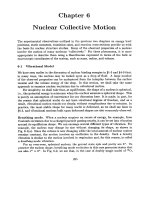
8.1.2 Entities and terminology
The following defines several entities and terms needed to understand mobile IP
as defined in RFC 3344 (Perkins, 2002; was: RFC 2002, Perkins, 1996a). Figure 8.1
illustrates an example scenario.
●
Mobile node (MN): A mobile node is an end-system or router that can
change its point of attachment to the internet using mobile IP. The MN
keeps its IP address and can continuously communicate with any other
system in the internet as long as link-layer connectivity is given. Mobile
nodes are not necessarily small devices such as laptops with antennas or
mobile phones; a router onboard an aircraft can be a powerful mobile node.
Figure 8.1
Mobile IP example
network
COA
Home
network
Router
HA
Router
FA
MN
Foreign
network
Internet
CN
Router
09Chap08 8804 (303-350)
308
30/5/03
11:05 am
Page 308
Mobile communications
●
●
●
●
●
●
Correspondent node (CN): At least one partner is needed for communication. In the following the CN represents this partner for the MN. The CN
can be a fixed or mobile node.
Home network: The home network is the subnet the MN belongs to
with respect to its IP address. No mobile IP support is needed within the
home network.
Foreign network: The foreign network is the current subnet the MN visits
and which is not the home network.
Foreign agent (FA): The FA can provide several services to the MN during
its visit to the foreign network. The FA can have the COA (defined below),
acting as tunnel endpoint and forwarding packets to the MN. The FA can be
the default router for the MN. FAs can also provide security services because
they belong to the foreign network as opposed to the MN which is only visiting. For mobile IP functioning, FAs are not necessarily needed. Typically,
an FA is implemented on a router for the subnet the MN attaches to.
Care-of address (COA): The COA defines the current location of the MN
from an IP point of view. All IP packets sent to the MN are delivered to the
COA, not directly to the IP address of the MN. Packet delivery toward the
MN is done using a tunnel, as explained later. To be more precise, the COA
marks the tunnel endpoint, i.e., the address where packets exit the tunnel.
There are two different possibilities for the location of the COA:
●
Foreign agent COA: The COA could be located at the FA, i.e., the COA
is an IP address of the FA. The FA is the tunnel end-point and forwards
packets to the MN. Many MN using the FA can share this COA as
common COA.
●
Co-located COA: The COA is co-located if the MN temporarily acquired
an additional IP address which acts as COA. This address is now topologically correct, and the tunnel endpoint is at the MN. Co-located addresses
can be acquired using services such as DHCP (see section 8.2). One problem associated with this approach is the need for additional addresses if
MNs request a COA. This is not always a good idea considering the
scarcity of IPv4 addresses.
Home agent (HA): The HA provides several services for the MN and is located
in the home network. The tunnel for packets toward the MN starts at the HA.
The HA maintains a location registry, i.e., it is informed of the MN’s location
by the current COA. Three alternatives for the implementation of an HA exist.
●
The HA can be implemented on a router that is responsible for the
home network. This is obviously the best position, because without
optimizations to mobile IP, all packets for the MN have to go through
the router anyway.
●
If changing the router’s software is not possible, the HA could also be
implemented on an arbitrary node in the subnet. One disadvantage of
this solution is the double crossing of the router by the packet if the MN
is in a foreign network. A packet for the MN comes in via the router; the
HA sends it through the tunnel which again crosses the router.
09Chap08 8804 (303-350)
30/5/03
11:05 am
Page 309
Mobile network layer
●
309
Finally, a home network is not necessary at all. The HA could be again
on the ‘router’ but this time only acting as a manager for MNs belonging to a virtual home network. All MNs are always in a foreign network
with this solution.
The example network in Figure 8.1 shows the following situation: A CN is
connected via a router to the internet, as are the home network and the foreign
network. The HA is implemented on the router connecting the home network
with the internet, an FA is implemented on the router to the foreign network.
The MN is currently in the foreign network. The tunnel for packets toward the
MN starts at the HA and ends at the FA, for the FA has the COA in this example.
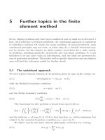
8.1.3 IP packet delivery
Figure 8.2 illustrates packet delivery to and from the MN using the example network of Figure 8.1. A correspondent node CN wants to send an IP packet to the
MN. One of the requirements of mobile IP was to support hiding the mobility of
the MN. CN does not need to know anything about the MN’s current location
and sends the packet as usual to the IP address of MN (step 1). This means that
CN sends an IP packet with MN as a destination address and CN as a source
address. The internet, not having information on the current location of MN,
routes the packet to the router responsible for the home network of MN. This is
done using the standard routing mechanisms of the internet.
The HA now intercepts the packet, knowing that MN is currently not in its
home network. The packet is not forwarded into the subnet as usual, but encapsulated and tunnelled to the COA. A new header is put in front of the old IP
header showing the COA as new destination and HA as source of the encapsulated packet (step 2). (Tunneling and encapsulation is described in more detail
in section 8.1.6.) The foreign agent now decapsulates the packet, i.e., removes
the additional header, and forwards the original packet with CN as source and
MN as destination to the MN (step 3). Again, for the MN mobility is not visible.
It receives the packet with the same sender and receiver address as it would have
done in the home network.
3.
Home
network
Router
HA
Router
FA
2.
MN
4.
Foreign
network
Internet
1.
CN
Router
Figure 8.2
Packet delivery to and
from the mobile node
09Chap08 8804 (303-350)
310
30/5/03
11:05 am
Page 310
Mobile communications
At first glance, sending packets from the MN to the CN is much simpler;
problems are discussed in section 8.1.8. The MN sends the packet as usual with
its own fixed IP address as source and CN’s address as destination (step 4). The
router with the FA acts as default router and forwards the packet in the same
way as it would do for any other node in the foreign network. As long as CN is a
fixed node the remainder is in the fixed internet as usual. If CN were also a
mobile node residing in a foreign network, the same mechanisms as described
in steps 1 through 3 would apply now in the other direction.
The following sections present some additional mechanisms needed for
mobile IP to work, some enhancements to the protocol, and some efficiency
and security problems.
8.1.4 Agent discovery
One initial problem of an MN after moving is how to find a foreign agent. How
does the MN discover that it has moved? For this purpose mobile IP describes
two methods: agent advertisement and agent solicitation, which are in fact
router discovery methods plus extensions.
8.1.4.1 Agent advertisement
For the first method, foreign agents and home agents advertise their presence
periodically using special agent advertisement messages. These advertisement
messages can be seen as a beacon broadcast into the subnet. For these advertisements Internet control message protocol (ICMP) messages according to RFC
1256 (Deering, 1991) are used with some mobility extensions. Routers in the
fixed network implementing this standard also advertise their routing service
periodically to the attached links.
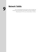
The agent advertisement packet according to RFC 1256 with the extension
for mobility is shown in Figure 8.3. The upper part represents the ICMP packet
while the lower part is the extension needed for mobility. The fields necessary
on lower layers for the agent advertisement are not shown in this figure. Clearly,
mobile nodes must be reached with the appropriate link layer address. The TTL
field of the IP packet is set to 1 for all advertisements to avoid forwarding them.
The IP destination address according to standard router advertisements can be
either set to 224.0.0.1, which is the multicast address for all systems on a link
(Deering, 1989), or to the broadcast address 255.255.255.255.
The fields in the ICMP part are defined as follows. The type is set to 9, the
code can be 0, if the agent also routes traffic from non-mobile nodes, or 16, if it
does not route anything other than mobile traffic. Foreign agents are at least
required to forward packets from the mobile node. The number of addresses
advertised with this packet is in #addresses while the addresses themselves
follow as shown. Lifetime denotes the length of time this advertisement is
valid. Preference levels for each address help a node to choose the router that is
the most eager one to get a new node.
09Chap08 8804 (303-350)
30/5/03
11:05 am
Page 311
Mobile network layer
0
7
8
15
16
23
24
31
type
code
checksum
#addresses
addr. size
lifetime
router address 1
preference level 1
router address 2
preference level 2
...
type = 16
length
registration lifetime
sequence number
R B H F MG r T
reserved
COA 1
COA 2
...
The difference compared with standard ICMP advertisements is what happens after the router addresses. This extension for mobility has the following
fields defined: type is set to 16, length depends on the number of COAs provided with the message and equals 6 + 4*(number of addresses). An agent shows
the total number of advertisements sent since initialization in the sequence
number. By the registration lifetime the agent can specify the maximum lifetime in seconds a node can request during registration as explained in section
8.1.5. The following bits specify the characteristics of an agent in detail. The R
bit (registration) shows, if a registration with this agent is required even when
using a colocated COA at the MN. If the agent is currently too busy to accept
new registrations it can set the B bit. The following two bits denote if the agent
offers services as a home agent (H) or foreign agent (F) on the link where the
advertisement has been sent. Bits M and G specify the method of encapsulation
used for the tunnel as explained in section 8.1.6. While IP-in-IP encapsulation is
the mandatory standard, M can specify minimal encapsulation and G generic
routing encapsulation. In the first version of mobile IP (RFC 2002) the V bit
specified the use of header compression according to RFC 1144 (Jacobson,
1990). Now the field r at the same bit position is set to zero and must be
ignored. The new field T indicates that reverse tunneling (see section 8.1.8) is
supported by the FA. The following fields contain the COAs advertised. A foreign agent setting the F bit must advertise at least one COA. Further details and
special extensions can be found in Perkins (1997) and RFC 3220. A mobile node
in a subnet can now receive agent advertisements from either its home agent or
a foreign agent. This is one way for the MN to discover its location.
311
Figure 8.3
Agent advertisement
packet (RFC 1256 +
mobility extension)
09Chap08 8804 (303-350)
312
30/5/03
11:05 am
Page 312
Mobile communications
8.1.4.2 Agent solicitation
If no agent advertisements are present or the inter-arrival time is too high, and an
MN has not received a COA by other means, e.g., DHCP as discussed in section
8.2, the mobile node must send agent solicitations. These solicitations are again
based on RFC 1256 for router solicitations. Care must be taken to ensure that these
solicitation messages do not flood the network, but basically an MN can search for
an FA endlessly sending out solicitation messages. Typically, a mobile node can
send out three solicitations, one per second, as soon as it enters a new network. It
should be noted that in highly dynamic wireless networks with moving MNs and
probably with applications requiring continuous packet streams even one second
intervals between solicitation messages might be too long. Before an MN even gets
a new address many packets will be lost without additional mechanisms.
If a node does not receive an answer to its solicitations it must decrease the rate
of solicitations exponentially to avoid flooding the network until it reaches a maximum interval between solicitations (typically one minute). Discovering a new agent
can be done anytime, not just if the MN is not connected to one. Consider the case
that an MN is looking for a better connection while still sending via the old path.
This is the case while moving through several cells of different wireless networks.
After these steps of advertisements or solicitations the MN can now receive
a COA, either one for an FA or a co-located COA. The MN knows its location
(home network or foreign network) and the capabilities of the agent (if needed).
The next step for the MN is the registration with the HA if the MN is in a foreign network as described in the following.
8.1.5 Registration
Having received a COA, the MN has to register with the HA. The main purpose
of the registration is to inform the HA of the current location for correct forwarding of packets. Registration can be done in two different ways depending
on the location of the COA.
●
●
If the COA is at the FA, registration is done as illustrated in Figure 8.4 (left).
The MN sends its registration request containing the COA (see Figure 8.5) to
the FA which is forwarding the request to the HA. The HA now sets up a
mobility binding containing the mobile node’s home IP address and the current COA. Additionally, the mobility binding contains the lifetime of the
registration which is negotiated during the registration process. Registration
expires automatically after the lifetime and is deleted; so, an MN should reregister before expiration. This mechanism is necessary to avoid mobility
bindings which are no longer used. After setting up the mobility binding, the
HA sends a reply message back to the FA which forwards it to the MN.
If the COA is co-located, registration can be simpler, as shown in Figure 8.4
(right). The MN may send the request directly to the HA and vice versa.
This, by the way, is also the registration procedure for MNs returning to
their home network. Here they also register directly with the HA. However,
if the MN received an agent advertisement from the FA it should register via
this FA if the R bit is set in the advertisement.
09Chap08 8804 (303-350)
30/5/03
11:05 am
Page 313
Mobile network layer
MN
Regis
t
requ ration
est
FA
HA
MN
Regis
t
requ ration
est
Figure 8.4 Registration
of a mobile node via the
FA or directly with the HA
ion
n
t
n
tratio
Regis
reply
HA
trat
Regis
reply
tratio
Regis
reply
Regis
t
requ ration
est
313
t
0
7
type 1
8
15 16
S B D MG r T x
23
24
31
lifetime
home address
home agent
COA
identification
extensions . . .
UDP packets are used for registration requests. The IP source address of the
packet is set to the interface address of the MN, the IP destination address is that
of the FA or HA (depending on the location of the COA). The UDP destination
port is set to 434. UDP is used because of low overheads and better performance
compared to TCP in wireless environments (see chapter 9). The fields relevant
for mobile IP registration requests follow as UDP data (see Figure 8.6). The fields
are defined as follows.
The first field type is set to 1 for a registration request. With the S bit an MN
can specify if it wants the HA to retain prior mobility bindings. This allows for
simultaneous bindings. The following bits denote the requested behavior for
packet forwarding. Setting the B bit generally indicates that an MN also wants to
receive the broadcast packets which have been received by the HA in the home
network. A more detailed description of how to filter broadcast messages which are
not needed by the MN can be found in Perkins (1997). If an MN uses a co-located
COA, it also takes care of the decapsulation at the tunnel endpoint. The D bit indicates this behavior. As already defined for agent advertisements, the following bits
M and G denote the use of minimal encapsulation or generic routing encapsulation, respectively. T indicates reverse tunneling, r and x are set to zero.
Figure 8.5
Registration request
09Chap08 8804 (303-350)
314
30/5/03
11:05 am
Page 314
Mobile communications
Figure 8.6
Registration reply
0
7
type = 3
8
15
16
code
31
lifetime
home address
home agent
identification
extensions . . .
Lifetime denotes the validity of the registration in seconds. A value of zero
indicates deregistration; all bits set indicates infinity. The home address is the
fixed IP address of the MN, home agent is the IP address of the HA, and COA
represents the tunnel endpoint. The 64 bit identification is generated by the
MN to identify a request and match it with registration replies. This field is used
for protection against replay attacks of registrations. The extensions must at
least contain parameters for authentication.
A registration reply, which is conveyed in a UDP packet, contains a type
field set to 3 and a code indicating the result of the registration request.
Table 8.1 gives some example codes.
Table 8.1 Example
registration reply codes
Registration
Code
Explanation
successful
0
registration accepted
1
registration accepted, but simultaneous mobility
bindings unsupported
65
administratively prohibited
66
insufficient resources
67
mobile node failed authentication
68
home agent failed authentication
69
requested lifetime too long
129
administratively prohibited
130
insufficient resources
131
mobile node failed authentication
132
foreign agent failed authentication
133
registration identification mismatch
135
too many simultaneous mobility bindings
denied by FA
denied by HA
09Chap08 8804 (303-350)
30/5/03
11:05 am
Page 315
Mobile network layer
315
The lifetime field indicates how many seconds the registration is valid if it
was successful. Home address and home agent are the addresses of the MN and
the HA, respectively. The 64-bit identification is used to match registration
requests with replies. The value is based on the identification field from the registration and the authentication method. Again, the extensions must at least
contain parameters for authentication.
8.1.6 Tunneling and encapsulation
The following describes the mechanisms used for forwarding packets between
the HA and the COA, as shown in Figure 8.2, step 2. A tunnel establishes a virtual pipe for data packets between a tunnel entry and a tunnel endpoint.
Packets entering a tunnel are forwarded inside the tunnel and leave the tunnel
unchanged. Tunneling, i.e., sending a packet through a tunnel, is achieved by
using encapsulation.
Encapsulation is the mechanism of taking a packet consisting of packet
header and data and putting it into the data part of a new packet. The reverse
operation, taking a packet out of the data part of another packet, is called
decapsulation. Encapsulation and decapsulation are the operations typically
performed when a packet is transferred from a higher protocol layer to a lower
layer or from a lower to a higher layer respectively. Here these functions are
used within the same layer.
This mechanism is shown in Figure 8.7 and describes exactly what the HA
at the tunnel entry does. The HA takes the original packet with the MN as destination, puts it into the data part of a new packet and sets the new IP header in
such a way that the packet is routed to the COA. The new header is also called
the outer header for obvious reasons. Additionally, there is an inner header
which can be identical to the original header as this is the case for IP-in-IP
encapsulation, or the inner header can be computed during encapsulation.
8.1.6.1 IP-in-IP encapsulation
There are different ways of performing the encapsulation needed for the tunnel
between HA and COA. Mandatory for mobile IP is IP-in-IP encapsulation as
specified in RFC 2003 (Perkins, 1996b). Figure 8.8 shows a packet inside the
tunnel. The fields follow the standard specification of the IP protocol as defined
original IP header
new data
new IP header
outer header
original data
inner header
original data
Figure 8.7
IP encapsulation
09Chap08 8804 (303-350)
316
Figure 8.8
IP-in-IP encapsulation
30/5/03
11:05 am
Page 316
Mobile communications
IHL
ver.
length
DS (TOS)
IP identification
flags
IP-in-IP
TTL
fragment offset
IP checksum
IP address of HA
Care-of address of COA
IHL
ver.
IP identification
TTL
length
DS (TOS)
flags
lay. 4 prot.
fragment offset
IP checksum
IP address of CN
IP address of MN
TCP/UDP/ . . . payload
in RFC 791 (Postel, 1981) and the new interpretation of the former TOS, now
DS field in the context of differentiated services (RFC 2474, Nichols, 1998). The
fields of the outer header are set as follows. The version field ver is 4 for IP version 4, the internet header length (IHL) denotes the length of the outer header
in 32 bit words. DS(TOS) is just copied from the inner header, the length field
covers the complete encapsulated packet. The fields up to TTL have no special
meaning for mobile IP and are set according to RFC 791. TTL must be high
enough so the packet can reach the tunnel endpoint. The next field, here
denoted with IP-in-IP, is the type of the protocol used in the IP payload. This
field is set to 4, the protocol type for IPv4 because again an IPv4 packet follows
after this outer header. IP checksum is calculated as usual. The next fields are
the tunnel entry as source address (the IP address of the HA) and the tunnel
exit point as destination address (the COA).
If no options follow the outer header, the inner header starts with the same
fields as just explained. This header remains almost unchanged during encapsulation, thus showing the original sender CN and the receiver MN of the packet.
The only change is TTL which is decremented by 1. This means that the whole
tunnel is considered a single hop from the original packet’s point of view. This
is a very important feature of tunneling as it allows the MN to behave as if it
were attached to the home network. No matter how many real hops the packet
has to take in the tunnel, it is just one (logical) hop away for the MN. Finally,
the payload follows the two headers.
8.1.6.2 Minimal encapsulation
As seen with IP-in-IP encapsulation, several fields are redundant. For example,
TOS is just copied, fragmentation is often not needed etc. Therefore, minimal
encapsulation (RFC 2004) as shown in Figure 8.9 is an optional encapsulation
method for mobile IP (Perkins, 1996c). The tunnel entry point and endpoint are
specified. In this case, the field for the type of the following header contains the
09Chap08 8804 (303-350)
30/5/03
11:05 am
Page 317
Mobile network layer
IHL
ver.
length
DS (TOS)
IP identification
flags
min. encap
TTL
317
Figure 8.9
Minimal encapsulation
fragment offset
IP checksum
IP address of HA
care-of address of COA
lay. 4 protoc.
S
IP checksum
reserved
IP address of MN
original sender IP address (if S=1)
TCP/UDP/ . . . payload
value 55 for the minimal encapsulation protocol. The inner header is different
for minimal encapsulation. The type of the following protocol and the address
of the MN are needed. If the S bit is set, the original sender address of the CN is
included as omitting the source is quite often not an option. No field for fragmentation offset is left in the inner header and minimal encapsulation does not
work with already fragmented packets.
8.1.6.3 Generic routing encapsulation
While IP-in-IP encapsulation and minimal encapsulation work only for IP, the
following encapsulation scheme also supports other network layer protocols in
addition to IP. Generic routing encapsulation (GRE) allows the encapsulation
of packets of one protocol suite into the payload portion of a packet of another
protocol suite (Hanks, 1994). Figure 8.10 shows this procedure. The packet of
one protocol suite with the original packet header and data is taken and a new
GRE header is prepended. Together this forms the new data part of the new
packet. Finally, the header of the second protocol suite is put in front.
Figure 8.11 shows on the left side the fields of a packet inside the tunnel
between home agent and COA using GRE as an encapsulation scheme according
to RFC 1701. The outer header is the standard IP header with HA as source
address and COA as destination address. The protocol type used in this outer IP
outer header
new header
GRE
header
original
header
original data
original
header
original data
new data
Figure 8.10
Generic routing
encapsulation
09Chap08 8804 (303-350)
318
Figure 8.11
Protocol fields for GRE
according to RFC 1701
30/5/03
11:05 am
Page 318
Mobile communications
IHL
ver.
length
DS (TOS)
IP identification
flags
fragment offset
GRE
TTL
IP checksum
IP address of HA
care-of address of COA
C R K S s rec.
rsv.
protocol
ver.
checksum (optional)
offset (optional)
key (optional)
sequence number (optional)
routing (optional)
IHL
ver.
IP identification
TTL
length
DS (TOS)
flags
lay. 4 prot.
fragment offset
IP checksum
IP address of CN
IP address of MN
TCP/UDP/. . . payload
header is 47 for GRE. The other fields of the outer packet, such as TTL and TOS,
may be copied from the original IP header. However, the TTL must be decremented by 1 when the packet is decapsulated to prevent indefinite forwarding.
The GRE header starts with several flags indicating if certain fields are present or not. A minimal GRE header uses only 4 bytes; nevertheless, GRE is
flexible enough to include several mechanisms in its header. The C bit indicates
if the checksum field is present and contains valid information. If C is set, the
checksum field contains a valid IP checksum of the GRE header and the payload. The R bit indicates if the offset and routing fields are present and contain
valid information. The offset represents the offset in bytes for the first source
routing entry. The routing field, if present, has a variable length and contains
fields for source routing. If the C bit is set, the offset field is also present and,
vice versa, if the R bit is set, the checksum field must be present. The only
reason for this is to align the following fields to 4 bytes. The checksum field is
valid only if C is set, and the offset field is valid only if R is set respectively.
GRE also offers a key field which may be used for authentication. If this
field is present, the K bit is set. However, the authentication algorithms are not
further specified by GRE. The sequence number bit S indicates if the sequence
number field is present, if the s bit is set, strict source routing is used. Sequence
numbers may be used by a decapsulator to restore packet order. This can be
important, if a protocol guaranteeing in-order transmission is encapsulated and
09Chap08 8804 (303-350)
30/5/03
11:05 am
Page 319
Mobile network layer
C
reserved0
ver.
checksum (optional)
protocol
reserved1 (=0)
transferred using a protocol which does not guarantee in-order delivery, e.g., IP.
Now the decapsulator at the tunnel exit must restore the sequence to maintain
the characteristic of the protocol.
The recursion control field (rec.) is an important field that additionally distinguishes GRE from IP-in-IP and minimal encapsulation. This field represents a
counter that shows the number of allowed recursive encapsulations. As soon as
a packet arrives at an encapsulator it checks whether this field equals zero. If the
field is not zero, additional encapsulation is allowed – the packet is encapsulated
and the field decremented by one. Otherwise the packet will most likely be discarded. This mechanism prevents indefinite recursive encapsulation which
might happen with the other schemes if tunnels are set up improperly (e.g., several tunnels forming a loop). The default value of this field should be 0, thus
allowing only one level of encapsulation.
The following reserved fields must be zero and are ignored on reception. The
version field contains 0 for the GRE version. The following 2 byte protocol field
represents the protocol of the packet following the GRE header. Several values
have been defined, e.g., 0 × 6558 for transparent Ethernet bridging using a GRE
tunnel. In the case of a mobile IP tunnel, the protocol field contains 0 × 800 for IP.
The standard header of the original packet follows with the source address
of the correspondent node and the destination address of the mobile node.
Figure 8.12 shows the simplified header of GRE following RFC 2784
(Farinacci, 2000), which is a more generalized version of GRE compared to RFC
1701. This version does not address mutual encapsulation and ignores several
protocol-specific nuances on purpose. The field C indicates again if a checksum
is present. The next 5 bits are set to zero, then 7 reserved bits follow. The version field contains the value zero. The protocol type, again, defines the
protocol of the payload following RFC 3232 (Reynolds, 2002). If the flag C is set,
then checksum field and a field called reserved1 follows. The latter field is constant zero set to zero follow. RFC 2784 deprecates several fields of RFC 1701, but
can interoperate with RFC 1701-compliant implementations.
8.1.7 Optimizations
Imagine the following scenario. A Japanese and a German meet at a conference
on Hawaii. Both want to use their laptops for exchanging data, both run mobile
IP for mobility support. Now recall Figure 8.2 and think of the way the packets
between both computers take.
If the Japanese sends a packet to the German, his computer sends the data to
the HA of the German, i.e., from Hawaii to Germany. The HA in Germany now
encapsulates the packets and tunnels them to the COA of the German laptop on
Hawaii. This means that although the computers might be only meters away, the
319
Figure 8.12
Protocol fields for GRE
according to RFC 2784
09Chap08 8804 (303-350)
320
30/5/03
11:05 am
Page 320
Mobile communications
packets have to travel around the world! This inefficient behavior of a nonoptimized mobile IP is called triangular routing. The triangle is made of the
three segments, CN to HA, HA to COA/MN, and MN back to CN.
With the basic mobile IP protocol all packets to the MN have to go through
the HA. This can cause unnecessary overheads for the network between CN and
HA, but also between HA and COA, depending on the current location of the
MN. As the example shows, latency can increase dramatically. This is particularly unfortunate if the MNs and HAs are separated by, e.g., transatlantic links.
One way to optimize the route is to inform the CN of the current location
of the MN. The CN can learn the location by caching it in a binding cache
which is a part of the local routing table for the CN. The appropriate entity to
inform the CN of the location is the HA. The optimized mobile IP protocol
needs four additional messages.
●
●
●
●
Binding request: Any node that wants to know the current location of an
MN can send a binding request to the HA. The HA can check if the MN has
allowed dissemination of its current location. If the HA is allowed to reveal
the location it sends back a binding update.
Binding update: This message sent by the HA to CNs reveals the current
location of an MN. The message contains the fixed IP address of the MN
and the COA. The binding update can request an acknowledgement.
Binding acknowledgement: If requested, a node returns this acknowledgement after receiving a binding update message.
Binding warning: If a node decapsulates a packet for an MN, but it is not the
current FA for this MN, this node sends a binding warning. The warning contains MN’s home address and a target node address, i.e., the address of the
node that has tried to send the packet to this MN. The recipient of the warning then knows that the target node could benefit from obtaining a fresh
binding for the MN. The recipient can be the HA, so the HA should now send
a binding update to the node that obviously has a wrong COA for the MN.
Figure 8.13 explains these additional four messages together with the case of
an MN changing its FA. The CN can request the current location from the HA. If
allowed by the MN, the HA returns the COA of the MN via an update message.
The CN acknowledges this update message and stores the mobility binding. Now
the CN can send its data directly to the current foreign agent FAold. FAold forwards
the packets to the MN. This scenario shows a COA located at an FA. Encapsulation
of data for tunneling to the COA is now done by the CN, not the HA.
The MN might now change its location and register with a new foreign
agent, FAnew. This registration is also forwarded to the HA to update its location
database. Furthermore, FAnew informs FAold about the new registration of MN.
MN’s registration message contains the address of FAold for this purpose. Passing
this information is achieved via an update message, which is acknowledged by
FAold. Registration replies are not shown in this scenario. Without the informa-
09Chap08 8804 (303-350)
30/5/03
11:05 am
Page 321
Mobile network layer
CN
HA
FAold
Data
FAnew
Data
Data
Data
Update
ACK
Data
Data
Figure 8.13
Change of the foreign
agent with an optimized
mobile IP
MN
Data
Update
ACK
MN changes
location
Registration
Data
Warning
Request
Update
ACK
Data
321
Data
t
tion provided by the new FA, the old FA would not get to know anything about
the new location of MN. In this case, CN does not know anything about the
new location, so it still tunnels its packets for MN to the old FA, FAold. This FA
now notices packets with destination MN, but also knows that it is not the current FA of MN. FAold might now forward these packets to the new COA of MN
which is FAnew in this example. This forwarding of packets is another optimization of the basic Mobile IP providing smooth handovers. Without this
optimization, all packets in transit would be lost while the MN moves from one
FA to another. With TCP as the higher layer protocol this would result in severe
performance degradation (see chapter 9).
To tell CN that it has a stale binding cache, FAold sends, in this example, a
binding warning message to CN. CN then requests a binding update. (The
warning could also be directly sent to the HA triggering an update). The HA
sends an update to inform the CN about the new location, which is acknowledged. Now CN can send its packets directly to FAnew, again avoiding triangular
routing. Unfortunately, this optimization of mobile IP to avoid triangular routing causes several security problems (e.g., tunnel hijacking) as discussed
in Montenegro (1998). Not all users of mobile communication systems want
to reveal their current ‘location’ (in the sense of an IP subnet) to a communication partner.
8.1.8 Reverse tunneling
At first glance, the return path from the MN to the CN shown in Figure 8.2
looks quite simple. The MN can directly send its packets to the CN as in any
other standard IP situation. The destination address in the packets is that of CN.
But there are several severe problems associated with this simple solution.
09Chap08 8804 (303-350)
322
30/5/03
11:05 am
Page 322
Mobile communications
●
●
●
Firewalls: Almost all companies and many other institutions secure their
internal networks (intranet) connected to the internet with the help of a firewall. All data to and from the intranet must pass through the firewall.
Besides many other functions, firewalls can be set up to filter out malicious
addresses from an administrator’s point of view. Quite often firewalls only
allow packets with topologically correct addresses to pass. This provides at
least a first and simple protection against misconfigured systems of
unknown addresses. However, MN still sends packets with its fixed IP address
as source which is not topologically correct in a foreign network. Firewalls
often filter packets coming from outside containing a source address from
computers of the internal network. This avoids other computers that could
use internal addresses and claim to be internal computers. However, this also
implies that an MN cannot send a packet to a computer residing in its home
network. Altogether, this means that not only does the destination address
matter for forwarding IP packets, but also the source address due to security
concerns. Further complications arise through the use of private addresses
inside the intranet and the translation into global addresses when communicating with the internet. This network address translation (NAT, network
address translator, RFC 3022, Srisuresh, 2001) is used by many companies to
hide internal resources (routers, computers, printers etc.) and to use only
some globally available addresses (Levkowetz, 2002, tries to solve the problems arising when using NAT together with mobile IP).
Multi-cast: Reverse tunnels are needed for the MN to participate in a multicast group. While the nodes in the home network might participate in a
multi-cast group, an MN in a foreign network cannot transmit multi-cast
packets in a way that they emanate from its home network without a
reverse tunnel. The foreign network might not even provide the technical
infrastructure for multi-cast communication (multi-cast backbone, Mbone).
TTL: Consider an MN sending packets with a certain TTL while still in its
home network. The TTL might be low enough so that no packet is transmitted outside a certain region. If the MN now moves to a foreign network,
this TTL might be too low for the packets to reach the same nodes as before.
Mobile IP is no longer transparent if a user has to adjust the TTL while
moving. A reverse tunnel is needed that represents only one hop, no matter
how many hops are really needed from the foreign to the home network.
All these considerations led to RFC 2344 (Montenegro, 1998) defining
reverse tunneling as an extension to mobile IP. The new RFC 3024 (Montenegro,
2001) renders RFC 2344 obsolete but comprises only some minor changes for
the original standard. The RFC was designed backwards-compatible to mobile IP
and defines topologically correct reverse tunneling as necessary to handle the
problems described above. Reverse tunneling was added as an option to mobile
IP in the new standard (RFC 3344).
09Chap08 8804 (303-350)
30/5/03
11:05 am
Page 323
Mobile network layer
Obviously, reverse tunneling now creates a triangular routing problem in
the reverse direction. All packets from an MN to a CN go through the HA. RFC
3024 does not offer a solution for this reverse triangular routing, because it is
not clear if the CN can decapsulate packets. Remember that mobile IP should
work together with all traditional, non-mobile IP nodes. Therefore, one cannot
assume that a CN is able to be a tunnel endpoint.
Reverse tunneling also raises several security issues which have not been
really solved up to now. For example, tunnels starting in the private network of
a company and reaching out into the internet could be hijacked and abused for
sending packets through a firewall. It is not clear if companies would allow for
setting up tunnels through a firewall without further checking of packets. It is
more likely that a company will set up a special virtual network for visiting
mobile nodes outside the firewall with full connectivity to the internet. This
allows guests to use their mobile equipment, and at the same time, today’s security standards are maintained. Initial architectures integrating mobility and
security aspects within firewalls exist (Mink, 2000a and b).
8.1.9 IPv6
While mobile IP was originally designed for IP version 4, IP version 6 (Deering,
1998) makes life much easier. Several mechanisms that had to be specified separately for mobility support come free in IPv6 (Perkins, 1996d), (Johnson, 2002b).
One issue is security with regard to authentication, which is now a required feature for all IPv6 nodes. No special mechanisms as add-ons are needed for
securing mobile IP registration. Every IPv6 node masters address autoconfiguration – the mechanisms for acquiring a COA are already built in. Neighbor
discovery as a mechanism mandatory for every node is also included in the
specification; special foreign agents are no longer needed to advertise services.
Combining the features of autoconfiguration and neighbor discovery means that
every mobile node is able to create or obtain a topologically correct address for
the current point of attachment.
Every IPv6 node can send binding updates to another node, so the MN can
send its current COA directly to the CN and HA. These mechanisms are an integral part of IPv6. A soft handover is possible with IPv6. The MN sends its new
COA to the old router servicing the MN at the old COA, and the old router encapsulates all incoming packets for the MN and forwards them to the new COA.
Altogether, mobile IP in IPv6 networks requires very few additional mechanisms of a CN, MN, and HA. The FA is not needed any more. A CN only has to
be able to process binding updates, i.e., to create or to update an entry in the
routing cache. The MN itself has to be able to decapsulate packets, to detect
when it needs a new COA, and to determine when to send binding updates to
the HA and CN. A HA must be able to encapsulate packets. However, IPv6 does
not solve any firewall or privacy problems. Additional mechanisms on higher
layers are needed for this.
323
09Chap08 8804 (303-350)
324
30/5/03
11:05 am
Page 324
Mobile communications
8.1.10 IP micro-mobility support
Mobile IP exhibits several problems regarding the duration of handover and the
scalability of the registration procedure. Assuming a large number of mobile
devices changing networks quite frequently, a high load on the home agents as
well as on the networks is generated by registration and binding update
messages. IP micro-mobility protocols can complement mobile IP by offering
fast and almost seamless handover control in limited geographical areas.
Consider a client arriving with his or her laptop at the customer’s premises.
The home agent only has to know an entry point to the customer’s network,
not the details within this network. The entry point acts as the current location.
Changes in the location within the customer’s network should be handled
locally to minimize network traffic and to speed-up local handover. The basic
underlying idea is the same for all micro-mobility protocols: Keep the frequent
updates generated by local changes of the points of attachment away from the
home network and only inform the home agent about major changes, i.e.,
changes of a region. In some sense all micro-mobility protocols establish a hierarchy. However, the debate is still going on if micro-mobility aspects should
really be handled on the IP layer or if layer 2 is the better place for it. Layer 2
mobility support would comprise, e.g., the inter access point protocol (IAPP) of
802.11 WLANs (see chapter 7) or the mobility support mechanisms of mobile
phone systems (see chapter 4).
The following presents three of the most prominent approaches, which
should be seen neither as standards nor as final solutions of the micro-mobility
problems. Campbell (2002) presents a comparison of the three approaches.
8.1.10.1 Cellular IP
Cellular IP (Valko, 1999), (Campbell, 2000) provides local handovers without
renewed registration by instaling a single cellular IP gateway (CIPGW) for each
domain, which acts to the outside world as a foreign agent (see Figure 8.14).
Inside the cellular IP domain, all nodes collect routing information for accessing
MNs based on the origin of packets sent by the MNs towards the CIPGW. Soft
handovers are achieved by allowing simultaneous forwarding of packets destined for a mobile node along multiple paths. A mobile node moving between
adjacent cells will temporarily be able to receive packets via both old and new
base stations (BS) if this is supported by the lower protocol layers.
Concerning the manageability of cellular IP, it has to be noted that the
approach has a simple and elegant architecture and is mostly self-configuring.
However, mobile IP tunnels could be controlled more easily if the CIPGW was
integrated into a firewall, but there are no detailed specifications in (Campbell,
2000) regarding such integration. Cellular IP requires changes to the basic
mobile IP protocol and is not transparent to existing systems. The foreign network’s routing tables are changed based on messages sent by mobile nodes.
These should not be trusted blindly even if they have been authenticated. This
could be exploited by systems in the foreign network for wiretapping packets
09Chap08 8804 (303-350)
30/5/03
11:05 am
Page 325
Mobile network layer
Figure 8.14
Basic architecture of
cellular IP
Internet
Mobile IP
CIP Gateway
data/control
packets
from MN1
BS
BS
BS
packets from
MN2 to MN1
MN1
MN2
destined for an MN by sending packets to the CIPGW with the source address
set to the MN’s address. In enterprise scenarios requiring basic communications
security, this may not be acceptable.
Advantage
●
Manageability: Cellular IP is mostly self-configuring, and integration of the
CIPGW into a firewall would facilitate administration of mobility-related
functionality. This is, however, not explicitly specified in (Campbell, 2000).
Disadvantages
●
●
●
325
Efficiency: Additional network load is induced by forwarding packets on
multiple paths.
Transparency: Changes to MNs are required.
Security: Routing tables are changed based on messages sent by mobile
nodes. Additionally, all systems in the network can easily obtain a copy of
all packets destined for an MN by sending packets with the MN’s source
address to the CIPGW.
8.1.10.2 Hawaii
HAWAII (Handoff-Aware Wireless Access Internet Infrastructure, Ramjee, 1999)
tries to keep micro-mobility support as transparent as possible for both home
agents and mobile nodes (which have to support route optimization). Its concrete goals are performance and reliability improvements and support for
quality of service mechanisms. On entering an HAWAII domain, a mobile node
obtains a co-located COA (see Figure 8.15, step 1) and registers with the HA
(step 2). Additionally, when moving to another cell inside the foreign domain,
the MN sends a registration request to the new base station as to a foreign agent
09Chap08 8804 (303-350)
326
30/5/03
11:05 am
Page 326
Mobile communications
Figure 8.15
Basic architecture
of HAWAII
Internet
HA
Backbone
Router
Crossover
Router
2
4
BS
BS
Mobile IP
BS
DHCP
Server
Mobile IP
3
MN
DHCP
MN
1
(step 3), thus mixing the concepts of co-located COA and foreign agent COA.
The base station intercepts the registration request and sends out a handoff
update message, which reconfigures all routers on the paths from the old and
new base station to the so-called crossover router (step 4). When routing has
been reconfigured successfully, the base station sends a registration reply to the
mobile node, again as if it were a foreign agent.
The use of challenge-response extensions for authenticating a mobile node
is mandatory. In contrast to cellular IP, routing changes are always initiated by
the foreign domain’s infrastructure, and the corresponding messages could be
authenticated, e.g., by means of an IPSec authentication header (AH; RFC 2402,
Kent, 1998), reducing the risk of malicious rerouting of traffic initiated by bogus
mobile hosts. However, this is not explicitly specified in Ramjee (1999). HAWAII
claims to be mostly transparent to mobile nodes, but this claim has to be
regarded with some caution as the requirement to support a co-located care-ofaddress as well as to interact with foreign agents could cause difficulties with
some mobile nodes.
Advantages
●
●
Security: Challenge-response extensions are mandatory. In contrast to
Cellular IP, routing changes are always initiated by the foreign domain’s
infrastructure.
Transparency: HAWAII is mostly transparent to mobile nodes.
09Chap08 8804 (303-350)
30/5/03
11:05 am
Page 327
Mobile network layer
327
Disadvantages
●
●
Security: There are no provisions regarding the setup of IPSec tunnels.
Implementation: No private address support is possible because of colocated COAs.
8.1.10.3 Hierarchical mobile IPv6 (HMIPv6)
As introducing hierarchies is the natural choice for handling micro-mobility
issues, several proposals for a ‘hierarchical’ mobile IP exist. What follows is
based on Soliman, (2002).
HMIPv6 provides micro-mobility support by installing a mobility anchor
point (MAP), which is responsible for a certain domain and acts as a local HA
within this domain for visiting MNs (see Figure 8.16). The MAP receives all
packets on behalf of the MN, encapsulates and forwards them directly to the
MN’s current address (link COA, LCOA). As long as an MN stays within the
domain of a MAP, the globally visible COA (regional COA, RCOA) does not
change. A MAP domain’s boundaries are defined by the access routers (AR)
advertising the MAP information to the attached MNs. A MAP assists with local
handovers and maps RCOA to LCOA. MNs register their RCOA with the HA
using a binding update. When a MN moves locally it must only register its new
LCOA with its MAP. The RCOA stays unchanged. To support smooth handovers
between MAP domains, an MN can send a binding update to its former MAP.
It should be mentioned as a security benefit that mobile nodes can be provided with some kind of limited location privacy because LCOAs on lower levels
of the mobility hierarchy can be hidden from the outside world. However, this
applies only to micro mobility, that is, as long as the mobile node rests in the
same domain. A MN can also send a binding update to a CN who shares the
same link. This reveals its location but optimizes packet flow (direct routing without going through the MAP). MNs can use their RCOA as source address. The
extended mode of HMIPv6 supports both mobile nodes and mobile networks.
Figure 8.16
Basic architecture of
hierarchical mobile IP
Internet
HA
RCOA
MAP
binding
update
AR
LCOAnew
MN
AR
LCOAold
MN