Lecture Electric circuit theory: First-order crcuits - Nguyễn Công Phương
Bạn đang xem bản rút gọn của tài liệu. Xem và tải ngay bản đầy đủ của tài liệu tại đây (363.22 KB, 41 trang )
Nguyễn Công Phương
Electric Circuit Theory
First-Order Circuits
Contents
I. Basic Elements Of Electrical Circuits
II. Basic Laws
III. Electrical Circuit Analysis
IV. Circuit Theorems
V. Active Circuits
VI. Capacitor And Inductor
VII. First-Order Circuits
VIII.Second Order Circuits
IX. Sinusoidal Steady State Analysis
X. AC Power Analysis
XI. Three-phase Circuits
XII. Magnetically Coupled Circuits
XIII.Frequency Response
XIV.The Laplace Transform
XV. Two-port Networks
First-Order Circuits - sites.google.com/site/ncpdhbkhn
2
First-Order Circuits
1.
2.
3.
4.
5.
6.
7.
8.
Introduction to Transient Analysis
Initial Conditions
The Source-free RC Circuit
The Source-free RL Circuit
Step Response of an RC Circuit
Step Response of an RL Circuit
The Classical Method
First-order Op Amp Circuits
First-Order Circuits - sites.google.com/site/ncpdhbkhn
3
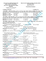
Introduction to Transient Analysis (1)
– +
– +
10 V
5Ω
10 V
t=0
0.1 H
0.1 H
i
2A
i
Any change in an
electrical circuit,
which brings about
a change in energy
distribution,
will result in a
transient-state.
5Ω
Steady-state
Transient-state
Steady-state t
0
12 V
v
Steady-state
Transient-state
Steady-state t
0
– +
– +
10 V
5Ω
12 V
t=0
0.1 mF
First-Order Circuits - sites.google.com/site/ncpdhbkhn
6Ω
0.1 mF
+
v
–
4
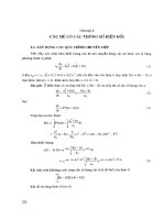
Introduction to Transient Analysis (2)
vL(t)
Inductors in
DC circuits
Transient
-state
Old steady-state
0
Short-circuit
Capacitors in
DC circuits
New steady-state
t
Not short-circuit
Short-circuit
iC(t)
Transient
-state
Old steady-state
New steady-state
0
Open-circuit
t
Not open-circuit
Open-circuit
First-Order Circuits - sites.google.com/site/ncpdhbkhn
5
Introduction to Transient Analysis (3)
First-Order Circuits - sites.google.com/site/ncpdhbkhn
6
First-Order Circuits
1.
2.
3.
4.
5.
6.
7.
8.
Introduction to Transient Analysis
Initial Conditions
The Source-free RC Circuit
The Source-free RL Circuit
Step Response of an RC Circuit
Step Response of an RL Circuit
The Classical Method
First-order Op Amp Circuits
First-Order Circuits - sites.google.com/site/ncpdhbkhn
7
20 V
Initial Conditions (1)
–+
–+
10 V
5Ω
t=0
i
0.1 H
i A
Steady-state/Initial condition 2
4
2A
Steady-state/Initial condition 1
5Ω
–+
10 V
t=0
i
0
0–
0.1 H
t
Prior to switching
0+
After switching
First-Order Circuits - sites.google.com/site/ncpdhbkhn
8
Initial Conditions (2)
• 1st switching rule/law: the current (magnetic flux) in an
inductor just after switching is equal to the current (flux) in the
same inductor just prior to switching
iL(0+) = iL(0–)
λ(0+) = λ(0–)
• 2nd switching rule/law: the voltage (electric charge) in a
capacitor just after switching is equal to the voltage (electric
charge) in the same capacitor just prior to switching
vC(0+) = vC(0–)
q(0+) = q(0–)
First-Order Circuits - sites.google.com/site/ncpdhbkhn
9
Initial Conditions (3)
Ex. 1
The switch has been at A for a long time,
and it moves to B at t = 0; find I0?
−
i (0 ) = 0 A
i (0+ ) = i (0− )
→ i(0+ ) = 0 A → I 0 = 0 A
–+
10 V
A
5Ω
t=0
B
i
0.1 H
Ex. 2
The switch has been at A for a long time,
and it moves to B at t = 0; find I0?
20
i (0 ) =
= 4A
5
–+
–+
−
i (0+ ) = i (0− )
20 V
→ i(0+ ) = 4 A → I 0 = 4 A
10 V
A
5Ω
t=0
B
First-Order Circuits - sites.google.com/site/ncpdhbkhn
i
0.1 H
10
Initial Conditions (4)
Ex. 3
The switch has been at A for a long time,
and it moves to B at t = 0; find V0?
−
v (0 ) = 0 V
+
−
v (0 ) = v(0 )
→ v (0 ) = 0 V → V0 = 0 V
+
–+
10 V
A
5Ω
t=0
B
0.1 mF
+
V0
–
Ex. 4
The switch has been at A for a long time,
and it moves to B at t = 0; find V0?
v (0− ) = 20 V
v (0+ ) = v(0− )
20 V
–+
–+
→ v (0+ ) = 20 V → V0 = 20 V
10 V
A
5Ω
t=0
B
First-Order Circuits - sites.google.com/site/ncpdhbkhn
0.1 mF
+
V0
–
11
First-Order Circuits
1.
2.
3.
4.
5.
6.
7.
8.
Introduction to Transient Analysis
Initial Conditions
The Source-free RC Circuit
The Source-free RL Circuit
Step Response of an RC Circuit
Step Response of an RL Circuit
The Classical Method
First-order Op Amp Circuits
First-Order Circuits - sites.google.com/site/ncpdhbkhn
12
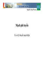
The Source-free RC Circuit (1)
iR + iC = 0
dv v
→C + =0
dt R
dv
v
→
+
=0
dt RC
dv
1
→
=−
dt
v
RC
t
→ ln v = −
+ ln A
RC
v
t
→ ln = −
A
RC
−
t
RC
→ v (t ) = Ae
v (0) = v t = 0 = V0
E
–+
iR
R
R
t=0
C
+
v
iC
C
–
v (0) = v t = 0 = V0
v
→ v (t ) = V0 e
−
= V0 e
t
RC
−
t
τ
V0
0.368V0
0
τ
First-Order Circuits - sites.google.com/site/ncpdhbkhn
t
13
The Source-free RC Circuit (2)
Ex. 1
+
R1 = 6 Ω; R2 = 12 Ω; vC(0) = 10 V;
C = 0.01F; find vC ?
R1
vC
C
R2
–
+
R12
C
τ = R12C = 4 × 0.01 = 0.04s
vC = vC (0)e
−
t
τ
= 10e
t
−
0.04
= 10e −25t V
vC
–
6 × 12
R12 =
= 4Ω
6 + 12
First-Order Circuits - sites.google.com/site/ncpdhbkhn
14
The Source-free RC Circuit (3)
Ex. 2
t=0
+
R2
R1
–
E
+
V0
E
t>0
vC
C
–
+
R2
V0 = 24 V
R1
–
–
V0 = E = 24 V
R1
–
t<0
+
R2
+
E = 24 V; R1 = 8 Ω; R2 = 12 Ω; C = 0.01F;
the switch has been closed for a long time,
and it is opened at t = 0; find vC for t ≥ 0?
τ = ( R1 + R2 )C = (8 + 12) × 0.01 = 0.2s
vC = V0 e
−
t
τ
= 24e
−
t
0.2
= 24e −5t V
First-Order Circuits - sites.google.com/site/ncpdhbkhn
15
First-Order Circuits
1.
2.
3.
4.
5.
6.
7.
8.
Introduction to Transient Analysis
Initial Conditions
The Source-free RC Circuit
The Source-free RL Circuit
Step Response of an RC Circuit
Step Response of an RL Circuit
The Classical Method
First-order Op Amp Circuits
First-Order Circuits - sites.google.com/site/ncpdhbkhn
16
The Source-free RL Circuit (1)
vR + vL = 0
di
→ Ri + L = 0
dt
di
R
→ = − dt
i
L
R
→ ln i = − t + ln A
L
i
R
→ ln = − t
A
L
E
–+
i
R
+
t=0
vR
L
–
R
–
L vL
+
i (0) = i t = 0 = I 0
i
I0
R
− t
L
R
− t
→ i(t ) = Ae
→ i(t ) = I 0 e L 0.368I0
i (0) = i t =0 = I 0
= I0e
−
t
τ
0
τ
First-Order Circuits - sites.google.com/site/ncpdhbkhn
t
17
The Source-free RL Circuit (2)
Ex.
t=0
R1
R3
+
L
R2
–
E = 24 V; R1 = 5 Ω; R2 = 4 Ω; R3 = 12 Ω;
L = 0.01H; the switch has been closed for
a long time, and it is opened at t = 0;
find iL for t ≥ 0?
iL
E
t<0
t>0
R1
R3
+
R2
R3
I0
L
R2
–
E
I0 = 0.75 A
4 × 12
24
Req = 5 +
= 8Ω → i1 =
= 3A
4 + 12
8
R2
4
→ I 0 = i1
=3
= 0.75 A
R2 + R3
4 + 12
τ=
L
0.01
=
= 0.000625s
R23 4 + 12
iL (t ) = I 0 e
−
t
τ
= 0.75e −1600 t A
First-Order Circuits - sites.google.com/site/ncpdhbkhn
18
First-Order Circuits
1.
2.
3.
4.
5.
6.
7.
8.
Introduction to Transient Analysis
Initial Conditions
The Source-free RC Circuit
The Source-free RL Circuit
Step Response of an RC Circuit
Step Response of an RL Circuit
The Classical Method
First-order Op Amp Circuits
First-Order Circuits - sites.google.com/site/ncpdhbkhn
19
Step Response of an RC Circuit (1)
+
E1
−
V0 = v(0 ) = v(0 ) = E1
Ri + v = E2
– +
E2
– +
→ ln(v − E2 ) V
v (t )
0
→
t=0
i
dv
v
E2
dv
+
=
→ RC + v = E2 →
dt RC RC
dt
dv
v − E2
→
=−
dt
RC
R
+
v
C –
dv
dt
=−
v − E2
RC
t
=−
RC
t
0
v − E2
t
→ ln
=−
V0 − E2
RC
→ v (t ) = E2 + (V0 − E2 )e
−
t
RC
t
−
v − E2
→
= e RC
V0 − E2
−
t
= E2 + ( E1 − E2 )e τ ,
First-Order Circuits - sites.google.com/site/ncpdhbkhn
t >0
20
Step Response of an RC Circuit (2)
v (t ) = E2 + (V0 − E2 )e
−
t
RC
−
t
= E2 + ( E1 − E2 )e ,
τ
E1
t>0
E2
– +
– +
R
t=0
i
Forced response/steady-state response
+
v
C –
Natural response/transient-state response
v
E2
v
v
V0 = E1
E2
V0 = E1
0
E2
t
0
t
0
First-Order Circuits - sites.google.com/site/ncpdhbkhn
t
21
First-Order Circuits
1.
2.
3.
4.
5.
6.
7.
8.
Introduction to Transient Analysis
Initial Conditions
The Source-free RC Circuit
The Source-free RL Circuit
Step Response of an RC Circuit
Step Response of an RL Circuit
The Classical Method
First-order Op Amp Circuits
First-Order Circuits - sites.google.com/site/ncpdhbkhn
22
Step Response of an RL Circuit (1)
E
I 0 = i(0 ) = i (0 ) = 1
R
di
di E2 − Ri
Ri + L = E2
→ =
dt
dt
L
di
dt
di
R
→
=
→
= dt
E2
E2 − Ri L
−i L
R
E2
t
t
−i
R
E
R
2
R
=− t
→ ln − i = − t → ln
E2
L
L 0
R
I0
− I0
R
+
−
E1
E2
–+
–+
R
t=0
L
i
E2
−i
R
− t
→ R
=e L
E2
− I0
R
E2
E2 − RL t E2 E1 E2 −τt
→ i(t ) =
+ I0 − e =
+ − e ,
R
R
R R R
First-Order Circuits - sites.google.com/site/ncpdhbkhn
t >0
23
Step Response of an RL Circuit (2)
E
E
i(t ) = 2 + I 0 − 2
R
R
E1
R
− Lt
e
E2 E1 E2 −τt
=
+ − e ,
R R R
t>0
E2
–+
–+
R
t=0
L
i
Forced response/steady-state response
Natural response/transient-state response
i
E2
R
i
v
I0 =
E2
R
E1
I0 =
R
0
t
0
t
E2
R
0
First-Order Circuits - sites.google.com/site/ncpdhbkhn
E1
R
24
t
First-Order Circuits
1.
2.
3.
4.
5.
6.
7.
8.
Introduction to Transient Analysis
Initial Conditions
The Source-free RC Circuit
The Source-free RL Circuit
Step Response of an RC Circuit
Step Response of an RL Circuit
The Classical Method
First-order Op Amp Circuits
First-Order Circuits - sites.google.com/site/ncpdhbkhn
25