Tài Liệu Đào Tạo Adui A8
Bạn đang xem bản rút gọn của tài liệu. Xem và tải ngay bản đầy đủ của tài liệu tại đây (13.94 MB, 108 trang )
Audi A8
(type 4N)
Self Study Programme 662
For internal use only.
Audi Service Training
< Back
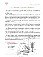
Launched in 1994, the Audi A8 was the world's first large-volume
production car with a self-supporting aluminium body. Since then,
Audi has built around a million cars with the Audi Space Frame
(ASF) body. Its successor, the A8 (type 4N), continues this tradition. The design of the new A8 perfectly embodies the fundamental qualities for which Audi is renowned – sports appeal, lightweight construction and quattro all-wheel drive. Stylistically, the
Audi A8 marks the beginning of a new design era for the entire
brand. The front end with its wide, upright Singleframe grille and
the fluid, muscular body symbolise sporty elegance, sophistication
and progressiveness. The defining design feature of the new
Audi A8 is spacious luxury; the cabin of the Audi A8 resembles a
spacious lounge with generous proportions.
Forward >
Ξ Contents
In comparison with the predecessor model, both body variants are
noticeably longer. The interior of the luxury saloon is deliberately
minimalist, with a clearly defined and strictly horizontal architecture. Audi carries its high quality standards into the digital age
with a radically new operating concept. The driver controls the
infotainment system with fingertip control on the large display.
The driver can use a second touchscreen display on the centre
tunnel console to access the air conditioning and comfort functions as well as making text inputs. The MHEV (mild hybrid electric vehicle) technology of Audi is based on the newly developed
48 volt electrical system – it supplies the 12 volt system, which in
this case becomes the electrical subsystem.
662_002
Learning objectives of this self study programme:
This self study programme describes the design and function of
the Audi A8 (type 4N). Once you have completed this self study
programme you will be able to answer questions on the following
topics:
2
>>
>>
>>
>>
>>
Engines available at launch
48 volt electrical system
New suspension features
New power transmission features
New features of the assistance systems
Contents
Introduction
Presentation __________________________________________________________________________________________________________________________________________________ 4
Dimensions ___________________________________________________________________________________________________________________________________________________ 6
Body
Introduction __________________________________________________________________________________________________________________________________________________ 8
Attachments _________________________________________________________________________________________________________________________________________________ 12
Interior equipment _________________________________________________________________________________________________________________________________________ 14
Roof variants _ _______________________________________________________________________________________________________________________________________________ 19
Engines
Petrol engine - diesel engine _______________________________________________________________________________________________________________________________ 20
Engine/gearbox combinations _____________________________________________________________________________________________________________________________ 21
Fuel tank _____________________________________________________________________________________________________________________________________________________ 22
SCR system (selective catalytic reduction) _ ______________________________________________________________________________________________________________ 24
Exhaust system for the 3.0l TFSI engine _________________________________________________________________________________________________________________ 26
Exhaust system for the 3.0l TFSI engine _________________________________________________________________________________________________________________ 27
Power transmission
Overview _____________________________________________________________________________________________________________________________________________________ 30
Automatic gearbox selector mechanism _ ________________________________________________________________________________________________________________ 32
Parking lock emergency release ___________________________________________________________________________________________________________________________ 33
8-speed automatic gearbox 0D5 __________________________________________________________________________________________________________________________ 34
Functions influencing the gearbox and sport differential _ _____________________________________________________________________________________________ 41
Suspension
Overview _____________________________________________________________________________________________________________________________________________________ 44
Axles and wheel alignment ________________________________________________________________________________________________________________________________ 45
Adaptive air suspension (aas) ______________________________________________________________________________________________________________________________ 46
Steering system _____________________________________________________________________________________________________________________________________________ 47
Suspension ___________________________________________________________________________________________________________________________________________________ 48
Wheels and tyres ____________________________________________________________________________________________________________________________________________ 49
Electrics and electronics
Installation locations of the control units ________________________________________________________________________________________________________________ 51
Air conditioning
Introduction of the new R744 refrigerant ________________________________________________________________________________________________________________ 52
New features of the Audi A8 _______________________________________________________________________________________________________________________________ 53
Safety and driver assistance systems
Passive safety ________________________________________________________________________________________________________________________________________________ 54
Active safety _________________________________________________________________________________________________________________________________________________ 74
Driver assistance systems __________________________________________________________________________________________________________________________________ 98
Infotainment and Audi connect
Overview of versions ______________________________________________________________________________________________________________________________________ 102
Inspection and maintenance
Overview ___________________________________________________________________________________________________________________________________________________ 104
Special tools and workshop equipment _________________________________________________________________________________________________________________ 106
Appendix
Self study programmes ___________________________________________________________________________________________________________________________________ 107
The self study programme teaches a basic understanding of the design and mode of operation of new models,
new automotive components or new technologies.
It is not a repair manual! Figures are given for explanatory purposes only and refer to the data valid at the
time of preparation of the SSP.
This content is not updated.
For further information about maintenance and repair work, always refer to the current technical literature.
Note
Reference
3
< Back
Forward >
Ξ Contents
Introduction
Presentation
Audi has reneegineered the 4th generation A8 (type 4N) from the
ground up. Thanks to a trendsetting design, state-of-the-art
suspension solutions, touchscreen operating concept and superla-
tive comfort, the luxury saloon demonstrates Vorsprung durch
Technik right across the board. Below you will find summarised the
key features of the Audi A8.
Engines
3.0l V6 TDI engine with mono turbocharger
>> Max. power: 210 kW (286 hp)
>> Max. torque: 600 Nm
3.0l V6 TFSI engine with mono turbocharger
>> Max. power: 250 kW (340 hp)
>> Max. torque: 500 Nm
The Audi A8 (type 4N) is the first Audi to come as
standard with an electrified driveline. For this
purpose, the engines are equipped with a mildhybrid system.
Displays and operation
A new operating and display concept incorporating
MMI touch response technology with 2 touchscreens, a switch panel (optional) and an illuminated button module with tactile and audible freeback, intelligent handwriting entry with
whole-word and multifinger recognition.
An Audi virtual cockpit with full HD resolution and
optional head-up display.
Driver assistance systems
For the first time, a central driver assistance
control unit (zFAS) utilises the data generated by
the sensors to comprehensively map the area
around the vehicle. This map is updated continuously and used by a number of assistance functions. For example, adaptive cruise assist is a new
driver assistance system, which is offered for the
first time in the Audi A8 (type 4N) as optional
equipment. It combines three formerly independent systems - adaptive cruise control, Audi active
lane assist with "early" corrective steering point
and traffic jam assist - in a single driver assist
system. Intersection assist helps the driver in situations in which cross traffic ahead of the vehicle
can only be seen late due to impaired visibility.
Suspension
The front and rear axles have a precision five-link construction (dynamic allwheel-drive steering is optional). A sport differential is available as an option
for even more dynamic handling. The adaptive air suspension has hydraulically controlled dampers which are adjustable to 4 height levels.
A fully active Audi A1 active suspension is optional. It controls each wheel
separately and allows a wide spread between comfort and sportiness.
4
< Back
Forward >
Ξ Contents
Air conditioning
Body
A further, new refrigerant is used in the Audi A8 (type 4N): carbon dioxide. It
has the chemical formula CO2 and is also known as R744. It contains neither
fluorine nor chlorine and is produced in a series of natural processes without
depleting the earth's ozone layer.
The body of the Audi A8 (type 4N) follows the Audi Space Frame (ASF) principle. It is assembled from aluminium parts – the classic composite of cast
nodal joints, extruded profiles and sheet metal. The occupant cell is made
from hot-formed steel components, complemented by an ultra-highstrength, torsionally rigid rear bulkhead made from carbon-fibre composite
(CFC). A magnesium dome strut completes the lightweight construction
concept.
662_068
Power transmission
Electrical system
8-speed automatic gearbox 0D5 has been redesigned and improved for the
Audi A8. The use of an auxiliary hydraulic pump allows the internal combustion to be shut off under coasting in certain situations. This saves fuel.
The rear final drive 0G2 is used on the rear axle.
The "quattro with sport differential" drive system with sport differential 0D3
is optional.
The MHEV technology of Audi is based on the newly developed 48 volt electrical system – it supplies the 12 volt electrical system, which in this case is
the electrical subsystem. The 48-volt electrical system is powered by a belt
alternator starter (BAS) which is connected to the engine belt drive. A lithium-ion battery, which is positioned safely under the luggage compartment
floor, serves as an energy storage device.
5
< Back
Forward >
Ξ Contents
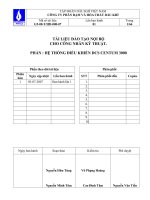
1488 (1473)
Dimensions
1049
1644
1633
1945
2130
662_074
697
105
1 1)
995
662_073
989
3128
1185
5302
662_075
697
983
104
8 1)
Illustration shows Audi A8 L
989
2998
1185
5172
Illustration shows Audi A8
6
662_071
14623)
15532)
Forward >
Ξ Contents
1159
840
15023)
15812)
< Back
662_076
Exterior dimensions and weights
Inner dimensions and other specifications
Length in mm
5302 (5172)
Front cabin width in mm
15812)
Width (not including exterior
mirrors) in mm
1945
Front shoulder width in mm
15023)
Width (including exterior
mirrors) in mm
2130
Rear cabin width in mm
15532)
Rear shoulder width in mm
14623)
Height in mm
1488 (1473)
Load sill height in mm
697
Front track width in mm
1644
505
Rear track width in mm
1633
Luggage compartment capacity
in l
Wheelbase in mm
3128 (2998)
Drag coefficient cw
0.27
Unladen weight in kg
1945 (1920)
Capacity of fuel tank in l
72/824)
Max. gross weight in kg
2745 (2680)
Maximum headroom
Elbow room width
3)
Shoulder room width
4)
Optional
The values given in brackets apply to standard wheelbase models.
1)
2)
All dimensions are given in millimetres and refer to the unladen weight of the vehicle.
7
< Back
Forward >
Ξ Contents
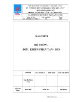
Body
Introduction
The new Audi A8 (type 4N) is based on an advanced ASF body
structure which, for the first time, is composed of different materials. With a mix of aluminium, steel, magnesium and carbon fibre
reinforced polymer (CFRP), the load-bearing structure combines
four different lightweight materials. However, the largest proportion (58%) is represented by aluminium components which, as cast
nodal plates, extruded sections and sheet metal panels, are the
characterisic elements of an ASF construction system.
A rear bulkhead made of carbon fibre saves around 50% compared
with its predecessor and helps to make the body rigid and strong in
spite of the lightweight design. The intelligent material mix is
completed by a dome strut which is 28% lighter and made of
magnesium A comparison with the topic of torsional rigidity shows
that the value has been improved by up to 24% compared with the
predecessor.
Key:
Sheet aluminium
Die-cast aluminium
Aluminium section
Ultra-high-strength steel (hot-stamped)
Carbon fibre reinforced polymer (CFRP)
Magnesium
Advanced high-strength steel
High-strength steel
Soft steel
Note
The depicted image shows an Audi A8 with a standard wheelbase. The body of the long-wheelbase version (A8 L) is 130 mm
longer in the vicinity of the B post and heel board.
8
< Back
Forward >
Ξ Contents
Connection system
The following connection systems are used when assembling the
multi-material body:
(Information refers to the Audi A8 body structure with the standard wheelbase without attachments).
>>
>>
>>
>>
Resistance spot welds on steel (1802 pcs.)
Resistance spot welds on aluminium (20 pics.)
MAG welds (total seam length: approx. 970 mm)
Laser welds on aluminium (total seam length:
approx. 4755 mm)
>> MIG welds (total seam length: approx. 5552 mm)
>> Friction element welds (242 pcs.)
>>
>>
>>
>>
>>
>>
Semi-tubular punch rivets (2583 pcs.)
Pop rivets (74 pcs.)
Flow drill screws (931 pcs.)
Clinch connections (82 pcs.)
Seaming (total seam length: approx. 15243 mm)
Bonding (total seam length: approx. 112014 mm)
662_192
9
< Back
Forward >
Ξ Contents
Safety cell
The occupant cell, also called the safety cell, is made of aluminium
and conventional hot-formed steel. The occupant cell comprises
the lower area of the end wall, the side sills, the B posts and the
front area of the roof arch. Some of these sheet metal blanks are
produced with different thicknesses using tailored technologies
and are also partially tempered if necessary. This reduces the
weight and increases the strength especially in extremely safetycritical areas.
662_193
B post
The B posts are adapted specially to the areas of body rigidity and
crash requirements, and are produced using tailor rolled blank
technology. These are flexibly rolled blanks, where variations in
sheet-metal thickness are produced by controlled opening and
closing of the gap between the rollers. These variations in sheetmetal thickness not only save weight, but also create defined
crumple zones which provide protection in the event side-on
impact. The sheet metal thicknesses vary between 1.5 mm and
2.0 mm.
Partial tempering: The individual zones of the B post are cooled in
the mould at different rates during hot working, giving them
different strength characteristics. In a side-on impact the bottom
section of the B post deforms in order to absorb energy. On the
other hand, less deformation takes place in the upper section of
the B post (at head height).
Ultra-high-strength
High-strength
662_194
10
662_195
< Back
Forward >
Ξ Contents
Roll hemming
In the new Audi A8 (type 4N) roll hemming is used all around for
the entire front and rear door sills. Passengers can therefore enter
and leave the vehicles more easily and the driver's field of vision in
the safety-related area of the A post can be enlarged. Improvements of up to 36 millimetres are therefore attained compared
with the predecessor model.
Roll hemming is complemented by grip punch riveting, which fixes
the side wall frame in its position, and supported by the all-round
structural bonding. Only by developing and adapting these joining
technologies is it possible to use the material concept in the
A8 (type 4N) and combine the aluminium side wall frame with the
hot-worked, ultra high strength sheet steel on the B post, roof arch
and sill with the narrow flanges.
Roll hemming
Grip punch rivet
662_197
Carbon fibre rear bulkhead
An ultra high strength, torsion-resistant rear bulkhead made of
carbon fibre is the largest component of the occupant cell in the
new Audi A8 (type 4N) and accounts for 33 per cent of the torsional rigidity of the overall vehicle. In order to fully absorb the
loads in the longitudinal or transverse direction and shear forces,
6 to 19 fibre layers are placed on top of one another for load
optimisation. These individual fibre layers are composed of
50-mm-wide bands which can be positioned individually at any
fibre angle and with a minimum fibre cut to create a finished layer
package.
662_198
B post
The carbon fibre rear bulkhead, which contains all fittings such as
the loudspeakers, the rear louvre, the 3-point belts and the centre
armrest, is inserted into the body through the rear window cutout
during final assembly by means of a handling device and is connected to the body structure using two-component strength
adhesive and rivets. The two-component strength adhesive prevents contact corrosion while a connection is created with the
adjacent body components in conjunction with the manually
affixed rivets.
Load application direction
662_196
11
< Back
Forward >
Ξ Contents
Attachments
Fully electric door lock
Another new feature of the A8 (type 4N) is the actuation of the
door locks. A so-called e-lock is used in which the opening signal is
transmitted electrically from the door inner handle or door outer
handle to the door control unit via a microswitch. The door control
unit in turn controls an electric motor which releases the rotary
latch, with the result that the lock opens. The microswitch for the
door outer handle is located in the support arm. It moves after a
few millimetres pressure on the door outer handle, the door
control unit triggers the electric motor in the e-lock and the door
can be opened with very little energy.
Exterior door handle switch
driver side F546
front pass. side F547
rear driver side F548
rear pass. side F549
662_103
Door handle, support arm and door lock in the rest state.
Emergency release mechanism
In order to still be able to open the doors if, for example, the
microswitch or the servo motor fails, 2 Bowden cables – 1 from the
interior door handle and 1 from the outer door handle – to the
door lock are available as before and form a mechanical connection
as a fallback level. However, in order to be able to open the door
mechanically, the interior door handle must be pulled far beyond
the normal angle. The door can only be opened using the outer
door handle after the locking cylinder or the interior door handle,
for example, was first actuated. The outer door handle can then be
pulled further than during normal actuation and with more energy.
662_104
Normal exterior door operation via the microswitch.
662_106
662_105
Interior door operation via a Bowden cable
12
Exterior door operation via a Bowden cable
< Back
Forward >
Ξ Contents
Door opening via the microswitch
The microswitch for opening the door is located in the interior door
handle. In this case, too, a brief pull on the interior door handle is
sufficient. When the door control unit detects the switch being
opened, it triggers the servo motor in the door lock.
662_107
Interior door handle in the rest state
Interior door handle switch
Driver side F550
Front pass. side F551
Rear driver side F552
Rear pass. side F553
662_108
Normal exterior door operation via the microswitch.
In certain situations, e.g. when a vehicle is detected within the
danger zone by the exit warning system, the e-lock can also delay
the opening of the door to be in a position to give both visual and
tactile warnings for a very short period of time.
Power latching
The Audi A8 (type 4N) can also again be fitted with an electric
power latching system for the doors as an optional extra. The
drives units here are new - motors for the power latching systems
V302, V303, V541 und V542, each of which no longer winds up
and unwinds the Bowden cable for the power latching system, but
exerts pull via an integrated linear drive and thereby moves the
rotary latch in the door lock to the end position.
Note
Before disconnecing the 12 Volt battery, make sure that one door glass, for example, is open or that the ignition key is not
inside the vehicle or in the luggage compartment.
Reference
You can find further information on the electric door lock in Self Study Programme 664, "Audi A8 (type 4N) - Electrics &
electronics".
13
< Back
Forward >
Ξ Contents
Interior equipment
Dash panel
A new operating concept not only in the MMI, but also, for
example, when actuating the light switch or the air vents of the air
conditioning systems also produced an entirely new design language in the interior of the Audi A8 (type 4N). Elegantly paired
with Audi's well-known quality, innovative solutions combined with
a new yet timeless design also create a completely new layout. The
upper trims for the dash panel are available as desired with wood
veneer or piano lacquer and form the wrap-around – the large arc
which runs above the door trim panels as far as the rear. This area
contains the air vents which are covered by these trims in the rest
state. When air from the automatic air conditioning system flows
directly into the interior, the shutters glide away upwards electrically while the air outlets move back a few centimetres,
i.e. towards the driver and the front passenger.
662_109
Design
Situated to the right and left of the central 10.1" touchscreen and
around the light switch, covers with the same black panel appearance as the display itself create an uninterupted area. The transition between this level and the level of the air vents is in turn
covered on the right and left by a trim strip. This modular design
must always be considered when performing dismantling work in
the area of the dash panel. In this case please always refer to the
instructions in the service literature.
Dash panel vent
Upper trim for dash panel
Trim strip
Cover in
black panel design
Dash panel vent
Upper trim for dash panel
Trim strip
Cover in black panel design
10.1" touchscreen, display unit for front information display
and operating unit control unit
J685
662_110
14
< Back
Forward >
Ξ Contents
Front centre console:
The black panel appearance of the dash panel is continued to the
centre console. The transition is made through a second, 8.6"
touchscreen with an operator control module at the bottom.
It is optionally available as a continuous touchscreen area integrated in the display optics.
662_111
Design
Thanks to the new design of the centre consoles at the front and
back, their layout has also been revised. The modular design and
therefore the latest repair instructions in ELSA must also be
observed during dismantling and assembly work. The illustrations
8.6" touchscreen, display
unit 2 for front information
display and operating unit
control unit J1060
published here show optional equipment or special features
according to the specific country and may therefore also differ
from equipment on your market.
Switch module in the centre of dash panel
EX22
Centre console switch module 1
EX23
Selector mechanism
662_112
15
< Back
Forward >
Ξ Contents
Rear centre console
Both Audi A8 body variants – with standard wheelbase and long
wheelbase - are equipped as standard with a 3-seat system at the
front, if required with a load-through hatch or a refrigerator box.
In the Audi A8 L there is also an individual seat system, then
without a non-folding centre armrest in the rear backrest, but with
a long, continuous centre console. It contains an armrest, large
storage compartments and, if required, folding tables, a 230 Volt
socket, a drinks holder, the Audi phone box, an SIM and SD card
reader and USB connections. Irrespective of whether the long,
continuous centre console or the folding centre armrest is fitted in
the rear backrest, the Audi A8 (type 4N) can be ideally equipped
with the Rear Seat Remote operating concept for passengers
sitting in the back. The Rear Seat Remote unit with its 5.7" OLED
display is roughly as big as a smartphone and is housed in the
centre armrest where it can be removed. The Rear Seat Remote
unit can be used to set convenience and infotainment functions in
the rear, e.g. seat positions, interior lights, louvres or the air
conditioning system for the rear. Another option are heated armrests in the centre armrests at the front and rear, and in the doors.
662_113
Mounting and charging cradle
for Smart Remote Control
Buttons for seat adjustment
Folding tables
Smart Remote Control,
wireless operating unit 1
E859
Audi phone box
662_114
Reference
You can find further information on the Rear Seat Remote unit in Self Study Programmes 665 "Audi A8 (type 4N) "New air
conditioning features and introduction of refrigerant R744" and 666 "Audi A8 (type 4N) Infotainment".
16
< Back
Forward >
Ξ Contents
Seats
The seats in the Audi A8 (type 4N) have also been redesigned from
scratch. The front seats are up to 4 kg lighter than in the predeces-
sor model, and glass fibre reinforced plastic (GFRP) is used in the
rear seats.
Front seats
The front seats are available in several designs. The top version is
the comfort individual contour seat. In addition to pneumatic seat
and backrest bolster adjustment, it also features as an option
heating and ventilation, each separately controllable in 3 stages.
The optional massage functions has also been extended.
Every backrest contains 16 small bubble-shaped air pockets,
3 above each other. They massage the entire back. For this
purpose, there is a choice of 7 programmes and 3 levels of intensity. A small compressor for each seat delivers up to 0.5 bar pressure.
Individual contour seat
Standard seat
662_115
Valve block 2
in driver seat
N476
Massage mat
Compressor for multi-contour seat
in driver seat
V439
Backrest bolster
adjustment
Valve block 1
in driver seat
N475
Air cushion for
lumbar support
Seat bolster
adjustment
662_116
17
< Back
Forward >
Ξ Contents
Rear seat
With the rear 3-seat system, the outer seats can be heated as an
option. The longitudinal position and the seat and backrest angle
can also be adjusted electrically. The lumbar support can then be
adjusted pneumatically. If desired, a massage function is also
available here with 18 triple air pockets per seat. The individual
seat system in the Audi A8 L also features the same adjustment
options as those in the rear 3-seat system.
Reclining seat
The first-class solution in the Audi A8 (type 4N) is the rear right
reclining seat. Its user can move it to a reclined position and place
his/her feet on an electrically folding area on the backrest of the
special passenger seat. If required, the feet are warmed and
massaged there in several stages. 3 intensities, 2 programmes and
3 foot sizes are available for this purpose. The entire foot reflex
zones are also stimulated. The rear passengers can lean their head
on the soft comfort head restraints in the new Kokon leather
version whose height here can be adjusted electrically. The reclining seat package features the comfort individual contour seats
with ventilation and massage, the long centre console with a
double folding table, the Rear Seat Remote operating unit, rear
seat entainment and four-zone deluxe automatic air conditioning.
662_117
Foot massage
18
Rear Seat Remote
Massage,
back area
Massage,
shoulder area
< Back
Forward >
Ξ Contents
Roof variants
Standard wheelbase
Depending on body type, there are 2 optional versions of the
panoramic glass sunroof. The A8 with a standard wheelbase has a
single-piece glass roof with 2 drain hoses at the rear. These drain
hoses will prevent ice from forming on the roof during low temperatures, which in turn could produce noise.
662_118
Long wheelbase
The Audi A8 L (type 4N) with a long wheelbease is fitted with a
two-piece glass roof. The front glass panel is movable while the
rear glass panel is fixed. Since drainage in this version is possible
via the front windscreen and rear window, no drain hoses are fitted
here. In both versions a glass cover is securely mounted in front of
the moveable panel.
662_119
19
< Back
Forward >
Ξ Contents
Engines
Petrol engine - diesel engine
Torque/power curve of 3.0l TFSI engine EA839
Torque/power curve of 3.0l TDI engine EA897evo2
Engine with code CZSE
Engine with code DDVC
Power output in kW
Torque in Nm
Power output in kW
Torque in Nm
662_087
Engine speed [rpm]
Features
Specifications
Engine code
CZSE
Engine speed [rpm]
662_004
DDVC
Type
V6 engine with 90° vee angle
V6 engine with 90° vee angle
Displacement in cm3
2995
2967
Stroke in mm
89.0
91.4
Bore in mm
84.5
83.0
Number of valves per cylinder
4
4
Firing order
1-4-3-6-2-5
1-4-3-6-2-5
Compression ratio
11.2 : 1
16.0 : 1
Power output in kW at rpm
250 at 5000 – 6400
210 at 4000
Torque in Nm at rpm
500 at 1370 – 4500
600 from 1250 – 3250
Fuel type
Premium unleaded 95 RON
Diesel to EN 590
Turbocharging
Exhaust turbocharger with wastegate
Monoturbo charger with VTG and E-positioner
Engine management
Bosch MDG 1
Bosch MD1 with OBD
Maximum injection pressure in bar
250
2000
Lambda/knock control
Adaptive lambda control, adaptive knock
control
Mixture formation
Direct injection
Direct injection
Exhaust gas treatment
2 close-coupled ceramic catalytic converters
Oxygen sensor before and after catalytic
converter
NOx storage catalyst with SCR-coated
diesel particulate filter
Emission standard
EU 6 plus/ LEV3 / Tier3
EU6 (ZD/E/F)
Concept
Mild hybrid 48V
Mild hybrid 48V
Reference
For further information about the utilised engines, please refer to Self Study Programme 655 "Audi 3.0l V6 TFSI engine of
EA839 series" and Self Study Programme 656 "3.0l TDI engine of EA897evo2 series"
20
< Back
Forward >
Ξ Contents
Engine/gearbox combinations
Use of the engine-gearbox combinations shown here is market-specific.
Engines
3.0l TFSI engine (CZSE) 250 kW
3.0l TDI engine (DDVC) 210 kW
8-speed automatic
gearbox 0D5
AL552-8Q
Rear axle drive
0G2
HL195.S3 M
PR no.:1) GH1
Rear axle drive
0D3 - sport differential
HL195.T2 M
PR no.:2) GH2
(optional)
Key to new manufacturer code designation
e.g.: 8-speed automatic gearbox
Automatic
planetary gear set
e.g.: Rear axle drive
rear
1)
2)
Longitudinal
mounting
Longitudinal mounting
AL552-8Q
Development number (indicating
torque capacity, generation and
position of front final drive)
Number of gears
Drive system (all-wheel
drive with integrated
transfer case/centre differential)
HL195.S3 M
Crown wheel diameter in mm
S = Standard
(unlocked differential)
T = Torque Vectoring
(sport differential)
1st generation
2nd generation
3rd generation
Manufacturer code:
M = Magna powertrain
Z = ZF Friedrichshafen AG
Production number GH1: Real axle differential basis (unlocked differential)
Production number GH2: Rear axle differential torque vectoring
21
< Back
Forward >
Ξ Contents
Fuel tank
The fuel tank is made of plastic and is fitted in filling levels with
72 litres and optionally with 82 litres. The interior workings are
the only difference between the TFSI and TDI design. A rollover
valve with a pressure retaining valve is fitted in the TFSI tank and a
refuelling shut-off valve is fitted in the liquid trap.
An immersion tube with different lengths is installed in the TDI
tank. A rollover valve is fitted at the bottom of the TDI/TFSI tank.
The end of the valve line is found at the top in the liquid trap and
also on the immersion tube.
Level sensor in
the top chamber
Example: TDI fuel tank
Roll-over vent valve
Filler neck for
SCR tank/AdBlue®
Filler neck
Vent line
662_058
TFSI filler neck
662_064
Non-return flap
Baffle
Metering pump for
auxiliary heater
Swirl pot with integrated
fuel filter in the delivery
module (long life) in the
TFSI tank
22
< Back
Liquid trap with
long refuelling
shut-off valve in
TFSI, 72 litres
Rollover valve with
pressure retaining
valve
Forward >
Ξ Contents
TDI with a long
immersion tube
for 72 litres
Refuelling
shut-off valve
Immersion tube
Liquid trap with
short refuelling
shut-off valve in
TFSI, 82 litres
TDI with a short
immersion tube
for 82 litres
662_059
Vent line
Baffle
Drive line for suction jet pump
Mixer tube on the transfer side
Level sensor in the secondary chamber
Intake manifold for suction jet pump
Rollover valve for the TDI / TFSI without a pressure retaining valve;
here, in the TDI, the open line terminates at the immersion tube
Level sensor in the main chamber
Fuel supply line for auxiliary heater
Fuel return line
Fuel supply line
662_057
23
< Back
Forward >
Ξ Contents
SCR system (selective catalytic reduction)
The reducing agent tank is an injection moulding (not an extruded
tank) made from two halves and welded. This has the advantage of
reducing weight. This means that allowance can be made in the
vehicle design for the integration of baffles and a heating system
adapted to the cabin as installation space. The reducing agent tank
has a capacity of 24 litres.
Reducing agent
filler neck
Equalisation chamber
Equalisation chamber
The ventilation system within the reducing agent tank is designed
in such a way that the tank can be filled with AdBlue® reducing
agent using pump nozzles. To be able to hold the reducing agent
flowing into the tank at a high flow rate, there is an equalisation
chamber in the SCR tank and in the filler neck. The returning
reducing agent would otherwise cause the pump nozzle to shut off
too early.
To prevent the flow-back of reducing agent in the filler neck, a
non-return flap is installed at the end of the filler neck.
Vent line
Reducing agent quality sensor
Filling line
In order to monitor the quality of the reducing agent (AdBlue®), a
reducing agent quality sensor G849 is fitted in the reducing agent
tank. It is located adjacent to the swirl pot on the bottom of the
reducing agent tank.
Non-return flap
Reducing agent quality sensor
G849
Outlet for draining
the reducing agent
662_049
Reducing agent metering system control unit
J880
Swirl pot
Reference
For further information about the SCR system, refer to Self Study Programme 632 "Audi Q7 (type 4M)".
24
< Back
Forward >
Ξ Contents
Swirl pot
The reducing agent sensor is an entirely electronic component and
does not require float contact points. An antenna (coil) and the
reducing agent (capacitive fluid) form an electrical resonant circuit.
A change in the fluid level alters the impedance of the circuit and
shifts the resonance frequency (5 MHz – 12 MHz) proportional to
the fluid level.
The resonance frequency is determined by a microcontroler by
coupling a high frequency signal into the medium and scanning the
upper frequency range. The microcontroller is located at the base
of the fluid level sensor. It computes the reducing agent level
using a temperature correction function. At the same time, the
functioning of the tank heater is checked by determining the
temperature.
Electrical connection for
tank heater
Non-return flap
662_102
Equalisation chamber in the tank
662_090
Tank heating mat
Electrical connection
for the swirl pot heater
Reducing agent tank sensor
G684
Reducing agent pump (SCR metering pump)
The pump is configured as a brushlessor electrically commutated three-phase
motor. It pumps the reducing agent to the reducing agent injector N474 via an
SCR pressure sensor. The pressure sensor for the reducing agent metering system
G686 measures the outlet pressure of the metering pump to the reducing agent
injector within a pressure range from -0.5 bar to approx. 9.0 bar (relative). The
reducing agent temperature sensor G685 measures the reducing agent temperature within a range from -40 °C to 80 °C.
Swirl pot with reducing agent pump
V437
Baffles
662_048
25