Nghiên cứu độ bền khung sát xi xe chữa cháy rừng đa năng tt tiếng anh
Bạn đang xem bản rút gọn của tài liệu. Xem và tải ngay bản đầy đủ của tài liệu tại đây (983.45 KB, 27 trang )
MINISTRY OF EDUCATION
AND TRAINING
MINISTRY OF AGRICULTURE
AND RURAL DEVELOPMENT
VIETNAM NATIONAL UNIVERSITY OF FORESTRY
VAN VAN LUONG
RESEARCH ON DURABILITY CHASSIS OF
MULTI-PURPOSE FOREST FIRE FIGHTING
VEHICLE
MAJORITY: MECHANICAL ENGINEERING
CODE NO: 9520103
SUMMARY OF
ENGINEERING DOCTORAL THESIS
Hanoi, 2020
Research work is completed at: Vietnam National University of
Forestry
Scientific instructors:
1. Assoc. Prof. Dr. QUANG THANH NGUYEN
2. Dr. TUONG VAN TRAN
Reviewer 1:
Reviewer 2:
Reviewer 3:
The defense will be taken in front of the Institutional Board of
Thesis Evaluation at: Vietnam National University of Forestry
At: … time, Date ….Month…..year 2020
The thesis can be found in the libraries:
National Library; Library - Vietnam National University of
Forestry; Library - Vinh Long University Of Technology Education
1
INTRODUCTION
1. The urgency of the thesis
In 2013, Vietnam National University of Forestry chaired the
implementation of state-level scientific research projects: "Research
technology and design and manufacture specialized equipment for forest fire
fighting", code No KC07.13/06-10. Results of the project designed and
manufactured multi-purpose forest fire fighting vehicles, forest fire-fighting
vehicles within the sample test area. However, when the fire-fighting vehicle
operating in the forest has no roads, under the impact of the forest ground,
obstructions on the way, the impact of the fire-fighting systems on the vehicle
makes the chassis was deformed, affecting the durability of the chassis
leading to the stability of the work of the vehicles and equipment on the
vehicle. The scientific basis for the completion of a multi-purpose forest fire
fighting vehicle (MFFV) is necessary to research to ensure the durability of
the chassis including the study of load modes acting on the chassis, stress,
and deformation, thereby providing technical solutions perfect vehicle
design. That is the reason research student chose and implemented the topic:
“Research on Durability Chassis of Multi-Purpose Forest Fire Fighting
Vehicle”.
2. Research objective of the thesis
Studying and evaluating the durability of the chassis is the scientific basis
for the completion of the structure of the chassis of MFFV.
3. Research subject
The research subject of the thesis is chassis of MFFV was product and
assembly in VietNam basic on Ural 4320 vehicle.
4. Research scope
Assessing the durability of static and fatigue of chassis under the effect
of the vertical load when the vehicle is moving on the road moving through
single-format bumpers and moving on the road with random.
5. New contributions of the thesis
2
- Has built a model to calculate static load, dynamic load acting on the
chassis during fire fighting.
- Has built the system of differential equations, surveyed to determine
the dynamic load acting on the chassis of MFFV.
- Has evaluated the static and fatigue strength of MFFV when the
vehicles are subjected to the maximum load, moving through the format
bump and the cars move on random roads.
- Tested to determine the dynamic load on the chassis and displacement
the frame at the survey position when the vehicle is moving on the real road.
The comparison between experiment and simulation has an acceptable error
value.
6. Scientific and practical significance
6.1. Scientific significance
The thesis has evaluated the durability of the chassis of MFFV. The
research results of the thesis serve as a scientific basis for the completion of
the structure of MFFV chassis.
6.2. Practical significance
The thesis has built a method to determine the dynamic load acting on
the chassis by model, built a method to assess the durability of the chassis, as
a scientific basis to build models to evaluate the durability of domestic design
and manufacturing products, contributing to perfecting the design process of
automotive components and assemblies.
The thesis can be used as a reference for truck manufacturers in Vietnam
during research and development of new designs as well as evaluating the
durability of the details of trucks of the same type.
CHAPTER 1
OVERVIEW OF RESEARCH ISSUES
1.1. Introduction multi-purpose forest fire fighting vehicle
Multi-purpose forest fire fighting vehicle manufactured by Vietnam is a
device that integrates many functions of forest fire fighting, including:
3
Cutting trees, clearing garbage grass, opening roads to create a fire isolation
corridor; sprinkler fire spraying area; create high-pressure wind to spray into
the fire; Use sandy soil in place to extinguish the fire.
1.2. Overview of MFFV chassis
The chassis of MFFV is the bearing element of the vehicle, on which the
engine, the assembly of the drivetrain, the operating part, the control
mechanism, cabin, load are installed. When built into a MFFV from a base
vehicle, the chassis is subjected to additional load from a set of fire fighting
equipment such as high-pressure water pumps, tree cutters to create a
separate corridor for fires and vacuums and high-speed blowing wind, sandblasting hoe quenched the fire, …
Chassis of MFFV has a total length of 7370mm, a width of 832mm,
including 2 main bars and 9 horizontal bars. Main bar structure (vertical
beams) No. 1 on each side consists of two bars with a thickness of 8mm
interlocking, the outer main bar is 7370mm long, the inner main bar has a
length of 5760mm from behind the chassis.
1.3. The method of researching the durability of the chassis
1.3.1. Research durability under maximum load
This is a traditional evaluation method, the durability of the chassis is
evaluated based on the maximum value of the vertical force in the Z-direction
calculated by the dynamic load coefficient when the vehicle is full load.
1.3.2. Study on durability under dynamic load conditions
The above static-stability method is only suitable for vehicles moving at
low speeds and not in large volumes. When the vehicle is moving at high
speed, the inertia of high-volume parts will generate dynamic loads, affecting
the breaking strength and durability of the chassis..
1.3.3. Study on fatigue resistance of concrete frames
1.3.3.1. Load from rough pavement
Excitation from the road surface causes dynamic loads that continuously
change over time acting on the chassis. Currently, the method of describing
4
pavement by random function has been standardized according to ISO 8608:
1995.
1.3.3.2. Study on fatigue resistance of concrete frames
n order to assess the fatigue strength of the component under cyclic
loading, it is often used empirically measured fatigue curve (also called S N curve). The different experimental results show that the number of loadbearing cycles corresponding to fatigue limits for steel and cast iron is
between 106 ÷ 108. Therefore, we can accept the hypothesis that The part will
not be broken by fatigue after withstanding 106 cycles.
1.4. Situation of close research in the world and Vietnam
1.4.1. Situation of researching in the world about designing and
manufacturing a chassis
The research chassis of the automobile are usually concentrated in
manufacturers,
factories,
manufacturing enterprises.
Therefore,
the
publication of the results of these research works is often limited by
technological know-how, copyright, and competition. The research works in
the world on the chassis are mainly in the form of announcing the results of
theoretical research for the chassis of trucks, passenger cars, etc. The author
realized that there was no research work to deal with the problem. to the
durability of the chassis of MFFV made by Vietnam.
1.4.2. Situation of research in Vietnam on designing, manufacturing chassis
Primitive studies are primarily presented in the textures of design and
design taught in engineering universities but at a limited level.
1.5. Research subjects
The research subject of the thesis is chassis of MFFV was product and
assembly in VietNam basic on Ural 4320 vehicle.
1.6. Content of the thesis
With the analysis presented above, the research student chooses to
perform the topic “Research on Durability Chassis of Multi-Purpose Forest
Fire Fighting Vehicle” to complete the structure of MFFV.
1.6.1. Objectives of the study
5
Studying and evaluating the durability of the chassis is the scientific
basis for the completion of the structure of the chassis of MFFV.
1.6.2. Research Methods
The thesis uses theoretical research methods combined with experimentation
with the content:
- Building a dynamic model of MFFV to determine the dynamic load on
the frame when the vehicle is moving under typical conditions;
- Building a 3-D model of MFFV chassis and durability assessment
survey by specialized software. Proposing the structure of an MFFV chassis
to ensure durable conditions during fire-fighting activities;
- Experiments verify automobile dynamics and finite element models
through determining dynamic load on the chassis and displacement at a point
on the frame when the vehicle moves through the format.
1.6.3. Research scope
Assessing the durability of static and fatigue of chassis under the effect
of a vertical load when the vehicle is moving on the road moving through
single-format bumpers and moving on the road with random.
1.6.4. Nội dung nghiên cứu
From the proposed research objectives, the thesis includes research contents:
- Overview;
- Building a model to study the durability of the chassis MFFV;
- Survey and evaluation of chassis durability;
- Experiment to determine the dynamic load acting on the frame and
displacement on the chassis;
- Conclude.
Conclusion of chapter 1
Today, with the strong development of software technology, the main
calculation tools used by scientists are structural analysis software. The
application of structural analysis software gives us reliable and less timeconsuming and cost-effective results, many of which have focused on static
and fatigue-resistant frame under effects. of the dynamic load from the
6
bumpy road surface. From the above analysis factors, the research on the
durability of the chassis of MFFV is necessary to complete the design and
construction of MFFV.
CHAPTER 2
BUILDING MODEL OF RESEARCH DURABILITY FOR CHASSIS
OF MULTI-PURPOSE FOREST FIRE FIGHTING VEHICLE
2.1. Methods to assess the durability of the chassis
2.1.1. Equivalent stress (Von Mises)
Equivalent stress (Von Mises) determined on deformation energy
theory. Currently specialized software allows export stress results in the form
of Von Mises. Therefore, to evaluate the durability of the MFFV chassis, the
thesis will use equivalent stress.
2.1.2. Assessing the durability of chassis fatigue
2.1.2.1. Variable load and fatigue limits
According to [48,63], the fatigue strength may also be calculated from
the material stress limit Su:
Se' 0,5Su , with Su ≤ 1400 MPa;
Se' 700 , with Su > 1400 MPa.
For cast iron materials, S e' valuable: Se' 0, 4Su [45,63].
2.1.2.2. Methods of assessing fatigue
The service life of a part depends mainly on two parameters of the
impact load, that is a and m. So, to assess the fatigue strength of the part,
people often use the relationship between the two parameters to evaluate
fatigue through the lifelines at fatigue limits. The relationship between a and
m forms the criteria for assessing fatigue strength. The thesis uses Ansys
software to calculate, the fatigue stress e s determined according to
Goodman standard:
a m 1
e Su n
2.2. Building a model of multi-purpose forest fire fighting vehicle
2.2.1. Building 3-D models multi-purpose forest fire fighting vehicle
7
Determining the mass and transient moments of the detailed parts of
forest fire trucks by experimental methods is difficult and expensive.
Therefore, building a 3-D model to determine the mass, moment of inertia of
the details, ... is the input parameter for the vehicle's oscillation problem..
2.2.2. Develop a model to calculate the durability of the chassis MFFV
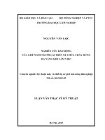
2.2.2.1. 3-D model chassis
Due
to
the
relatively
complicated structure, the 3-D
model
needs
to
be
built
correctly. In this study, the
author uses Solidworks software Figure 2.6: 3-D model chassis MFFV
to build 3-D models.
2.2.2.2. Enter the model into Ansys
After designing the 3-D model in Solidworks, we proceed to import the
chassis model into the Ansys Workbench environment.
2.2.2.3. Assign materials
In Ansys provide very large proven material inventory with reality.
2.2.2.4. Mesh model
In this study, the
meshing
method
was
chosen as the automatic
type in combination with
manual mesh adjustment.
The model consists of
174223
elements
and Figure 2.10: Finite element model on the chassis
376982 buttons.
MFFV
2.2.2.5. Boundary conditions
Tweezers have a role to limit the displacement of the frame in 3
translational directions in the xyz plane and the rotation directions. So we
choose the mount at the tweezers catch position. The forces acting on the
8
chassis, we converted to separate positions according to each force acting.
For simplicity, we return to the main forces as follows:
- Engine block: Worth weight 12258N (figure 2.12).
- Cabin cluster: Weights 8340N evenly distributed on the chassis
according to the points described in figure 2.13.
Figure 2.12: Weight distribution of
engine cluster acting on the frame
Figure 2.13: Weight distribution of cabin
assembly acts on the frame
- Container volume: Including the entire weight of the container, with a
payload value of 118500N.
- In addition to the weight of the three basic blocks above, the MFFV
also weights the front cut cluster of 9810N, grass clippers, and rear hoe
valued 7848 N.
2.2.2.6. Export results
After performing the calculation, the software will obtain equivalent
stress, deformation, displacement in the form of the color spectrum. In
addition to the analytical results in the static problem, we can give the
problem of persistent results over time.
2.3. Building a model to determine the dynamic load acting on the chassis
2.3.1. Method of modeling
To build the dynamic model of the MFFV using this method, include
the following steps:
- Make initial assumptions;
- The definition of a reference system;
- Set up the system of differential equations;
- Solving software differential equations (numerical method).
9
After solving the system of differential equations, we determine the
acceleration of the axles in the vertical direction. Taking the acceleration
times the weight of the bridge in the static state we determine the dynamic
load from the road surface acting on the chassis through the bridge.
2.3.2. Building space model
2.3.2.1. Some assumptions when building models
- The tank is full of water and views the water in the tank as a solid mass
because the tank is divided into several small compartments. The link
between the cabin and chassis, the tank, and the chassis is like a suspension
link consisting of an elastic and a damper shown on the space model..
The weight of the cabin is considered to be hard, the cabin has three
movements: moving in the Z direction, turning around the horizontal axis (Yaxis), and turning around the vertical axis (X-axis).
The part of the weight of the box is considered to be hard, the 3-motion
container is moved in the Z direction, rotated around the horizontal axis (Yaxis), and rotated around the vertical axis (X-axis).
The chassis has 3 movements: moving in the Z direction, turning around
the horizontal axis (Y-axis), and turning around the vertical axis (X-axis).
The mass that is not suspended is considered as absolute stiffness, the
suspended mass has two movements: moving in the Z direction
corresponding to the front, middle and back axles.
The weight of the front cutting device, the rear lawn cutter, is considered
to be absolutely hard, with two movements: moving in the Z direction and
turning around the vertical axis (X-axis).
Ignore the source of vibration on the vehicle, considering the forest
ground and the impulses due to the grass cutting machine is the only source
of vibration. The contact between the wheels and the road surface is the point
contact and ignores the slip between the wheels and the road. Vehicles
moving on the road at a low and constant speed. Therefore it is considered
that the inertial resistance and the air resistance are equal to zero. Ignore the
effect of wheel drive friction.
10
2.3.2.3. Space model of MFFV
Figure 2.15: Oscillating model of MFFV in space
Structural model of MFFV with 19 extrapolated coordinates (19 DOF)
include: 3 DOF of cabin (Zc, θcx, θcy), 3 bDOF of the tank (Zt, θtx, θty), 3 DOF
of chassis (Zs, θsx, θsy), 2 DOF of the front axle (Zu1, θu1), 2 DOF of middle
axle (Zu2, θu2), 2 DOF of rear axle (Zu3, θu3), 2 DOF of cut the tree forward
(Z4, θ4) and 2 DOF of rear lawn cutter (Z5, θ5).
2.3.2.4. Establish a system of differential equations describing the MFFV
The system of differential equations of oscillations can be formulated
based on the second law of Newton. These equations have been established
through balancing force and torque acting on the object. In this study, the
author only gave 3 equations describing the displacement of the front,
middle, and rear bridges.
mu1Z u1 K s1 2Zu1 2Z s 2 sy l1 K L1 2Z u1 h11 h12
Cs1 2Zu1 2Z s 2 sy l1 CL1 2Zu1 h11 h12 0
2Z
C
mu2 Zu2 K L 2 2Zu 2 h21 h22 Cs 2 2Zu 2 2Z s 2sy l2 l5 CL 2 Zu 2 h21 h22 0
mu3 Zu3 K L3
u3
h31 h32
s3
2Zu 3 2Z s 2sy l2 l5 CL3 2Zu 3 h31 h32 0
11
2.4. Calculation to determine dynamic load
Dynamic loads from the pavement acting on the chassis through tires
and bridge cover are determined from the dynamical model of the car.
Investigate dynamic loads in including cases:
- Vehicles moving straight on the road going through the bumpy format;
- Vehicles moving straight on the bumpy road by ISO 8608: 1995.
2.4.1. Vehicles moving straight on the road encounter bump
Call Fz11, Fz12, Fz21, Fz22, Fz31, Fz32 s the reaction from the road surface
acting on the left, right, left, right, right, and left front wheels respectively.
The survey case with bumpy format included: Single contour 2 front wheels;
bump, put 1 on the front wheel, rear wheel; Ripped unset set 2 wheels. The
survey results are the components placed on the poker frame. These results
serve as an input to the survey of the durability of the chassis (chapter 3) and
comparison with the verification test model (chapter 4).
Figure 2.31a: Dynamic load Fz1 when
Figure 2.31b: Dynamic load Fz3 when
the front and left wheels are bumping
(v = 20 km/h, h = 0,4m)
the front and left wheels are bumping (v
= 20 km/h, h = 0,4m)
2.4.2. Vehicles moving straight on bumpy roads according to ISO 8608:
1995
12
Figure 2.34a: Bumpy road surface D-E (v =
20 km/h)
Figure 2.34b: Bumpy road surface E-F (v =
20 km/h)
Figure 2.35a: Front axle load FZ1 (v =
Figure 2.35b: Rear axle load FZ3 (v = 20
20 km/h, D-E)
km/h, D-E)
Figure 2.36a: Front axle load FZ1 (v =
Figure 2.36b: Rear axle load FZ3 (v = 20
20 km/h, E-F)
km/h, E-F)
When the vehicle runs at a speed of v = 20 km / h on the road E-F, the
maximum value of maximum frontal vertical force Fz1max is 42762,9 N,
maximum vertical force value at 1,412 compared with the case of static
loading (stationary vehicle). For the rear axle, the maximum value of
maximum vertical middle force Fz3max is 40852,1 N. The Maximum vertical
force is 1.60 times higher than in case of static load (stationary vehicle).
Conclusion of chapter 2
Chapter 2 has built a 3-D model of the chassis by Solidworks and has
built a model to study the durability of the frame by finite element method
based on specialized software Ansys.
Developed a model to determine the dynamic load on the chassis based
on the dynamic analysis model of the vehicle when moving on the road. A
13
system of differential equations has been established, from which vertical
loads from the road surface can be applied to the chassis when the vehicle is
moving on the road when the wheels are deformed and moving on two roads
is bad (DE) and very bad (EF) according to ISO 8608: 1995 corresponding
to different speeds.
CHAPTER 3
SURVEY DURABILITY CHASSIS OF MULTI-PURPOSE FOREST
FIRE FIGHTING VEHICLE
3.1. The regime of durability according to the load
In this survey study, the loads acting on the chassis cover the case:
- Case 1: The chassis is subjected to a static maximum load;
- Case 2: Vehicles moving on the road are subjected to the maximum
vertical jet from the road surface acting on the chassis when one of the front
wheels, front wheels, rear wheels, and two wheels cross each other to meet
the road surface.;
- Case 3: Vehicles moving on random bumpy road according to ISO
8608: 1995 (D-E and E-F roads) are subjected to vertical reaction effects on
the chassis..
3.2. Analyze individual vibration of frame
Separate vibration analysis of the frame is a linear analysis method to
determine the specific vibration frequency of the frame [11,41]. The purpose
of determining the frame's unique vibration frequency is to avoid resonance
that occurs when the vehicle is operating.
In the separate oscillation analysis of the frame, if the mass matrix [M]
and hardness matrix [C] constant then the value of force acting on the frame
is 0. The linear equation in the natural oscillation problem to determine the
vibration frequency is as follows [11, 58]:
M u C u 0
The results of the analysis of vibration and vibration frequency of the
frame by Ansys software for the chassis are shown in table 3.1.
14
Mode
1
2
3
4
5
6
7
8
9
10
Table 3.1: The specific format and frequency of the MFFV
Frequency Deformation Mode Frequency Deformation
(Hz)
(mm)
(Hz)
(mm)
17.812
3.4996
11
100.58
4.6058
31.436
2.4011
12
103.55
8.8978
54.127
4.1007
13
111.42
13.564
63.506
2.347
14
114.53
2.8216
64.404
4.5987
15
115.75
14.297
76.248
5.0434
16
124.61
6.1435
77.961
4.4542
17
129.88
6.6524
82.337
0.3608
18
133.73
6.9162
98.081
3.1975
19
138.64
15.304
100.21
3.2097
20
140.1
14.795
3.3. Assess the destructive strength of the chassis MFFV
3.3.1. Cases with maximum load
3.3.1.1. The chassis is subject to the maximum static load
Bảng 3.2: Deformation, maximum stress on
chassis close to maximum static load
Deformation
Stress
(mm)
(MPa)
Maximum
3.2138
191.41
Figure 3.8: Von Mises on the chassis and
the position of maximum value
The analytical results show that the maximum stress is 191.41 MPa,
lower than the limit value of flow, and destruction of materials is 785 MPa
and 980 MPa, so the cement frame ensures durable conditions in the field.
3.3.1.2. Where front-wheel encounter bump
Figure 3.18: Maximum deformation on
Figure 3.19: Von Mises max on the
the chassis when the front wheel must
encounter bumpy, bumpy height
changes
chassis when the front wheel must
encounter bumpy, bumpy height
changes
15
The results of the analysis when the front wheel was encountered bumpy
road surface (road surface height varies) shows that the maximum stresses
are greater than the flow limit value of the material is 785 Mpa, so the cement
frame does not guarantee breaking conditions in this case. Therefore, it is
necessary to insert a xi rod like the rear main bar, and increase the thickness
of the inner and outer main bar by 10mm to ensure durability. The results of
the improved survey frame durability with main bar size 10 + 10 show the
highest equivalent stress value when the front wheel encountered a bump
with a value of 470.69 MPa, smaller than the gender value the yield term of
the material is 785 MPa.
3.3.1.3. Where the front two wheels encountered bump
bumpy
height
Table 3.4: Maximum deformation and
stress on the chassis when the two front
wheels encounter a bump
Figure 3.26: Equivalent stress on the
0.1m
Deformation
(mm)
118
Stress
(MPa)
879.67
0.2m
232.79
1850.2
0.3m
321.92
2628.7
0.4m
422.77
3481.4
chassis when the two front wheels met
bumpy, bump height 0.4m
The analysis results show that the maximum stresses are greater than the
yield limit of the material is 785 MPa. When the height of the pavement is
0.1m, the equivalent stress is 879.67 MPa, which is nearly equal to the
destruction limit and 980 MPa, so the cement frame does not guarantee
durable conditions in this case. Therefore, to reduce stress in this case, it is
necessary to increase the thickness of the main bar. When increasing the main
bar thickness to 10mm, the survey results show that the highest equivalent
stress value appears on the smaller frame smaller than the yield and
destruction limits of the material.
16
3.3.1.4. Where rear-wheel encounter bump
Figure 3.38: Maximum deformation on the
chassis when the rear wheel must encounter
bumpy, bumpy height changes
Figure 3.39: The max equivalent stress on
the chassis when the rear wheel is facing a
bump, the height of the pavement is changed
3.3.1.5. In the case of two cross-wheels (front left and right)
Table 3.6: Maximum deformation and
stress on the chassis when the two
diagonal wheels encounter a bump
bumpy
height
mô
0.1m
0.2m
0.3m
0.4m
Deformation
(mm)
134.96
175.61
255.51
335.41
Stress
(MPa)
612.04
1927
2817
3707
Figure 3.46: Equivalent stress on the
chassis when the two diagonal wheels
encountered bump, bump height 0.4m
Table 3.7: Compare values of equivalent stress concentration points and maximum
displacement on the original frame
Survey case
Equivalent stress max (MPa)
Height bumpy road surface (m)
0.1
0.2
0.3
0.4
Right front wheel bump
928.93
1190.5 1735.9 2280.9
Distorted front wheels
879.67
1850.2 2628.7 3481.4
Right rear wheel bumpers
304.65
830.62 1533.6 2236.5
Distorted two cross wheels
612.04
1927
2817
3707
3.3.2. Assess the durability of the chassis under the dynamic loads
The conditions for the
load and the effective
mount are the same as in
the static problem in the
case where the chassis is
subjected
to
the
Figure 3.60: Dynamic equivalent stress distributed
maximum load..
over the upper cylinder frame (E-F line)
17
The analysis results of the dynamic load problem on the chassis of
versatile forest fire trucks show that the stress is relatively evenly distributed
over the entire detailed surface. When moving on the road E-F, the stress
generated on the chassis is more valuable when the vehicle is moving on the
road D-E. The maximum value recorded is 357.26 MPa less than the
allowable stress, in this case to ensure the breaking conditions of the chassis.
3.4. Evaluate fatigue strength of chassis of the MFFV
In this survey content, assess
the fatigue strength of the chassis in
case the chassis is subjected to
dynamic loads with the mode of
regular
operation
of
vehicles
moving on very bad roads..
Figure 3.63: The number of fatigue
cycles on the chassis while moving on
the road E-F
Dynamic load applied to the chassis when the vehicle is moving on DE and E-F roads according to ISO 8608: 1995 with a travel speed of 20 km /
h determined from the dynamic model.
On the E-F road, the smallest number of fatigue cycles is worth 6349.9
cycles. It is found that the number of fatigue cycles on the chassis on both
types of roads is less than 106, so the chassis does not guarantee fatigue
conditions at work.
For the chassis after the improvement by increasing the main crosssection size 10 + 10mm, while increasing the cross-section of the horizontal
bar No. 20 (Figure 1.10) 12mm thick to ensure durable conditions in the event
of destruction. After the improvement, it shows that when the vehicle is
moving on the E-F road, the smallest number of fatigue cycles is 106,
therefore, the chassis ensures fatigue condition. After improving the weight
of the cylinder frame weighing 1361kg, an increase of 346.6 kg compared to
the original weight (1014.4kg).
18
Conclusion of chapter 3
Investigated stress and displacement of the chassis in case of
maximum static load. The survey results show that the largest stresses
appearing on the cement frame reaches 190.73MPa lower than the yield and
destruction limits of materials are 785MPa and 980 MPa, so the cement frame
ensures durable event destroyed in this case.
Investigation of stresses and displacements of the chassis in case the
wheels were stimulated by the pavement.
Evaluated the breaking strength and fatigue strength of the chassis
which is subjected to the load from the pavement surface D-E and E-F
following ISO 8608: 1995 with a speed of 20 km/h.
Investigation of the breaking strength and fatigue strength of the
improved poker frame showed that when increasing the main bar inside and
outside by 10mm thick, and the horizontal bar No. 20 (figure 1.10) with the
thickness of 12mm, the frame is close. xi satisfies working conditions. Other
details of the crosshair frame with size and position do not change.
CHAPTER 4
EXPERIMENTAL STUDY
4.1 Purpose and subject of the experiment
4.1.1. Purpose of the experiment
The purpose of the experiment is to determine the vertical reaction from
the road surface acting on the wheel when the vehicle moves through the
format bump, determining the bending deformation at the position of the
chassis. Experimental results are compared with theoretical calculation
results to verify the simulation model of the thesis.
4.1.2. Experimental subjects
The object of the experiment is MFFV manufactured and assembled in
Vietnam. It is fitted with full fire fighting equipment and full load.
4.2. Measured parameters
Parameters to be measured in experiments include:
19
- The perpendicular jet from the road surface acts on the wheel
vertically Fz (kN);
- Deformation at a point on the chassis in the z-direction (mm).
4.3. Select method and measuring equipment
The test to determine the normal force from the pavement acting on the
wheel and displacement at a point on the frame can be used to measure nonelectrical quantities with the application of a tenzo conversion with a bending
load on. The measuring system includes sensors and components that receive,
amplify, convert, process, display, and store measurement results.
4.4. Methods and laboratory equipment
4.4.1. Experimental determination of normal force
To measure vertical normal
force, research students using a
resistor
bridge.
Four
tenzo
resistors are placed in parallel and
arranged symmetrically on the top
and the bottom of the bridge at 12
o'clock and 6 o'clock (top 2 leaves,
lower side 02 leaves).
Figure 4.4: Tenzo stuck on the bridge
4.4.2. Experiment to determine the deformation at a point on the chassis
Experiment to determine the deformation at
a point on the chassis, research students also use
resistors, including 4 tenzo resistors affixed
symmetrically above and below the xi frame
(upper surface 2 resistor leaves, lower side 02 Figure 4.6: Tenzo paste
resistor leaves). The position of resistor foil is on
position on the chassis
the right frame, the resistor leaf is stuck on the
frame between the cabin and the container,
60mm from the front of the container.
4.4.3. Devices, sensors, and software used in the experiment
4.4.3.1. Experimental equipment
20
To collect, amplify, and convert measurement information into digital
signals, Ph.D. students use Spider8 device manufactured by HBM, Federal
Republic of Germany.
4.4.3.2. The sensor
To determine the relationship between the voltage the resistance change
on the resistor foil and the load acting on the bridge. Research student uses
the Z4 load cell during the standard understanding of measured values.
To measure the deformation of the chassis when calibration we use the
WSF d deformation sensor of Germany.
4.5. Calibrate measured values
4.5.1. Calibrate the measured value of the normal force
Calibrate the normal jet
measurement value to determine
the relationship between the
voltage measured at the resistor
bridge and the force acting on the
bridge shell, thereby determining
the correct value of the normal
force from the pavement acting Figure 4.11: Calibration of normal jet
on the wheel in units of N.
measurement value
Table 4.3: Results of standard vertical force measurement
Force [kN]
Voltage [mV]
0 5 10 15
20
0 4.7 9.5 13.8 18.3
25
30
35
22.6 27.1 31.2
40
35.5
45 50
39.8 44.2
4.5.2. Calibration of frame deformation measurement
Similar to the calibration of normal force measurement, calibration of
frame deformation measurement is used to determine the relationship
between the voltage measured at the resistor bridge glued to the frame and
the deformation of the frame at the Tenzo paste position..
21
Table 4.4: The result of taking the displacement frame of chassis
Voltage out [mV]
Deformation
(mm)
0
2.75 5.06 7.53 10.12 12.72 15.2
17.03 19.54
0
1.13 5.36 10.64 15.79 21.11 25.68 30.232 36.23
4.6. Conduct experiments on the road
The experiment was conducted on asphalt roads when one side of the
wheel passed over the pavement and was carried out on a forestry road in Lot
mountain of the Forestry University..
Experimental plans include:
- Experiment 1: Vehicles moving on flat roads, moving right front
wheels, performed at 3 speeds of 10, 15 and 20 km/h;
- Experiment 2: Vehicles moving on flat roads, moving the right rear
wheels, performed at 3 speeds of 10, 15, and 20 km/h.
4.7. Experimental results
4.7.1. Normal jet measurement results
Experimental
are
compared
results
with
the
simulation results in the
same conditions (when the
vehicles running on the rear
wheels have to be distorted
format, speed 10, 15, 20 Figure 4.21: Comparing results between
km/h) to assess the accuracy simulation and experiments when the wheels
of the tissue.
have to bump, the speed is 20 km/h
Table 4.5: Compare vertical force results between simulation (Sim) and experiment (Exp)
V = 10 km/h
V = 15 km/h
V = 20 km/h
Eror
Eror
Error
Sim
Exp
Sim
Exp
Sim
Exp
(%)
(%)
(%)
Fz32max
44.86
45.89 2.23 67.15
62.44
7.02 76.36
74.94
1.87
(kN)
Fz32min
4.99
6.01
16.8
-15.4
-14.41
6.49 -28.8
-25.41 11.84
(kN)
Comparison between simulation and experiment, the results show that
the law of vertical force variation according to theoretical calculations and
22
measured experimentally is the same. Comparing the maximum deviation
between theory and experiment is done by taking large values, subtracting
small values, and dividing by large values. The largest deviation between
simulation results and experimental results is 16.8%..
4.7.2. Results of displacement measurement of the chassis
b. Experiment
a. Simulation
Figure 4.26: Move the chassis close to the front wheel when bumping, speed 20 km /h
Bảng 4.6: Compare the deformation results on the chassis between simulation and
experiment
V = 10 km/h
Deformation
(mm)
V = 15 km/h
Sim
Exp
Eror
(%)
8.72
7.58
15.1
Sim
22.01
Exp
Eror
(%)
V = 20 km/h
Error
Sim
Exp
(%)
18.25
20.5
20.9
26.5
26.1
Conclusion of chapter 4
- In chapter 4, selected methods, equipment, subjects, and testing
process were suitable to the existing conditions in Vietnam, The experiment
has determined the dynamic load acting on the chassis and the displacement
of the chassis at the measuring position. Tenzo sensors have been used
according to the principle of Wheatstone bridge so that the dynamic load is
applied to the chassis and the displacement of the chassis at the measuring
position. Experimental results are plentiful and reliable. The comparison of
the maximum values of vertical and displacement forces between simulation
and experiment results shows that the maximum deviations are 16.8% and
26.1%.
23
CONCLUDE
1. The thesis has built the method of assessing the durability of the
chassis of MFFV by using Ansys software. A dynamic model of MFFV has
been built, set up the system of differential equations, building algorithm
diagram in Matlab Simulink to determine dynamic loads from the pavement
acting on the chassis with different pavement conditions and velocities.
2. The thesis has evaluated the destructive strength to be carried out in
cases where the chassis is subjected to maximum load, chassis is loaded with
loads when the wheels face a bump in different heights. With the abovementioned cases showing that the wheel faces a bump in the road, the
maximum stresses appearing on the chassis are mostly greater than the stress
and destruction limits of the material are 785 MPa and 980 MPa, therefore,
the chassis is not guaranteed to be durable.
3. The thesis has evaluated the destruction of the chassis which is
subjected to the load from the pavement surface D-E and E-F following ISO
8608: 1995 with a speed of 20 km/h. Destructive durability survey shows that
when the road is very bad (E-F), the stress generated on the chassis is more
valuable when the vehicle is moving on the bad road (D-E). The maximum
value recorded on the D-E line is 314.1 MPa and the E-F line is 357.26 MPa,
smaller than the allowable stress limit so the cement frame ensures durable
conditions.
4. The thesis has evaluated the fatigue strength of the original frame
and improved frame by Ansys software with dynamic load determined from
the dynamic model, D-E, and E-F pavement according to ISO 8608: 1995
with a speed of 20 km/h. Survey results show that the original frame does not
guarantee fatigue conditions when working, for improved chassis, it ensures
fatigue.
5. The thesis has identified and proposed the structure of MFFV
chassis to ensure durable conditions when vehicles move on the fire-fighting
operation road.