Serial Interface (SCI)
Bạn đang xem bản rút gọn của tài liệu. Xem và tải ngay bản đầy đủ của tài liệu tại đây (624.27 KB, 18 trang )
h t t p : / / r e s o u r c e . r e n e s a s . c o m Page 129
Chapter 11
Serial Interface (SCI)
The serial interface is a communication function having two types:
start-stop synchronization and clock synchronization. This chapter describes
the start-stop synchronization type, which has a wider range of applications.
Although a multiprocessor function is added to the H8/3048 serial interface,
this function is not explained here since it is specific to the series and not
provided for other processors.
The serial interface has more registers than peripheral functions
described earlier and the operation may seem more complex. You need to
completely understand the meaning of the settings regarding the contents of
each register.
Since the training board is connected to your PC through the serial
interface, you can use the PC as I/O equipment by developing a program to
send and receive characters using ASCII codes.
Note
The following register has negative logic bit names:
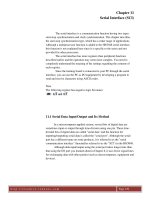
11.1 Serial Data Input/Output and Its Method
In a microcomputer-applied system, several bits of digital data are
sometimes input or output through time-division using one pin. These time-
divided bits of digital data are called "serial data" and the function for
inputting/outputting serial data is called the "serial port". Although the serial
port has a different name on some products, it is referred to as the "serial
communication interface" (hereinafter referred to as the "SCI") in the H8/3048.
Although data input/output using the serial port takes longer time than
that using the I/O port you learned about in Chapter 8, it uses fewer signal lines
for exchanging data with other parties (such as microcomputers, equipment and
devices).
h t t p : / / r e s o u r c e . r e n e s a s . c o m Page 130
Figure 11.1: Serial Data Input/Output
As such, the serial port is mostly used for input/output with more
distant parties, for which connection using a large number of signal lines is
unsuitable. Data input/output using the serial port is often referred to as
"communication", with input being referred to as "reception" and output
"transmission".
Serial data communication is conducted via the RS-232C and USB
(Universal Serial Bus) ports, used to connect PCs and peripherals, as well as
data communication using Ethernet or telephone lines.
Figure 11.2: Serial Data Formats
h t t p : / / r e s o u r c e . r e n e s a s . c o m Page 131
Start-stop synchronization communicates 7- or 8-bit data per operation
and the transmit pin outputs the high-level voltage while data are not
transmitted. When transmission is started, the start bit, one bit of the low-level
voltage, is output to notify the other party of the start of data transmission and
7- or 8-bit data are output. After that, the parity bit is output if an error is
detected. At the end of transmission, the stop bit, a high-level voltage, is
output, which consumes one or two bits.
As shown above, start-stop synchronization has several data formats.
There are two requirements to communicate through start-stop
synchronization: one is for the sender and receiver to use the same data format
and the other is for them to use the same transmission speed (also called "baud
rate", which refers to how many bits are communicated per second; the unit is
bit per second, or bps). Communication will fail unless these two are
predetermined between sender and receiver.
11.2 SCI Operation Overview
The H8/3048 has two SCI channels which can be set to either start-stop
synchronization or clock synchronization. Although the figure below shows a
block diagram of only one SCI channel, both have the same configuration and
use.
Figure 11.3: SCI Block Diagram
For transmission, the CPU writes the data to be transmitted in the
transmit data register (TDR). After that, the SCI moves the data from the TDR
to the transmit shift register (TSR), which outputs them from the transmit pin
h t t p : / / r e s o u r c e . r e n e s a s . c o m Page 132
(TxD) bit by bit in the set data format through some modification such as
adding the start or stop bit.
For reception, the data input in the receive pin (RxD) are stored in the
receive shift register (RSR) bit by bit through some modification such as
removing the start or stop bit. After that, the SCI moves the data from the RSR
to the received data register (RDR) when the stop bit arrives and the CPU reads
them using the MOV instruction.
In communication using the SCI, the data to be transmitted are written
in the TDR and the received data are read from the RDR. Although the TSR
and RSR exist inside the SCI, they are not assigned an address in the memory
since users need not operate them. The SCI has four more registers for
controlling other settings such as communication operation, which are
described in the following section.
11.3 SCI Registers
Table 11.1 shows the SCI register configuration. The following
explains how to transmit and receive serial data using the SCI in sequence
together with introduction of each register.
Table 11.1: SCI Register Configuration (for 2 Channels)
11.3.1 Communication Mode and Data Format Setting
The SCI is equipped with a serial mode register (SMR), which is
designed to set the communication mode and data format.
Figure 11.4: Serial Mode Register (SMR)
h t t p : / / r e s o u r c e . r e n e s a s . c o m Page 133
C/A The communication mode bit is designed to set use of start-stop or clock synchronization.
Bits 6 to 2 are effective only when this bit is set to 0.
CHR The character length bit is designed to set the data bit length.
PE The parity enable bit is designed to set use of parity bit or not.
O/E The parity mode bit is designed to set even or odd parity when the parity bit is set to be
used. If it is set not to be used, the setting of this bit is ineffective.
STOP The stop bit length bit is designed to set the stop bit length.
MP The description of the multiprocessor mode bit is omitted in this lesson.
CKS The lower 2 clock select bits are designed to select the clock to be used to generate the
baud rate among four using a combination of 1 and 0. The SCI communication speed is
determined by three factors, one of which is the clock select bits. How it is determined is
described in detail in the next section.
11.3.2 Setting of Communication Speed
Figure 11.5 shows the bit rate register (BRR), which is used to
determine the communication speed.
Figure 11.5: Bit Rate Register (BRR)
The SCI communication speed is determined by the following three
factors:
1. Clock select bits in the SMR (CKS1 and CKS0)
2. Value written in the BRR
3. Microcomputer operating frequency (same as the oscillating frequency
of the crystal oscillator externally connected to the microcomputer)
Table 11.2 shows how the communication speed is determined by these three
factors.
For example, to set the communication speed to 9600 bauds (the same unit as
bps) when the microcomputer operating frequency is 20MHz (same as when
the crystal XTAL is 20MHz), read the values of N and n from this table. N
refers to the value to be set in the BRR and n to the one to be set in the clock
select bits in the SMR. Since N = 64 and n = 0 at 9600 bauds, the clock select
bits (CKS1 and CKS0) are both 0. A communication speed of 9600 bauds can
be achieved by writing these values in each register.
Table 11.2: Sample Settings of BRR for Baud Rates (Start-stop
Synchronization)
h t t p : / / r e s o u r c e . r e n e s a s . c o m Page 134
11.3.3 Communication Procedure
Figure 11.6 shows the serial status register (SSR), which is an
important register for transmitting or receiving data.
Figure 11.6: Serial Status Register (SSR)
All of the upper 5 bits of this register serve as the status flag. If you are
not sure about the use, review how to use each flag. The lower 3 bits are not
described here since they are not used so often.
TDRE The transmit data register empty (TDRE) flag is used for transmitting data. Refer to
Figure 11.7 for the transmission procedure.
Before writing the data to be transmitted in the transmit data register (TDR), make sure
that the TDRE is set to 1. If it is still set to 0, you should not write data in the TDR yet.
If the TDRE is set to 1, write the data to be transmitted in the TDR, then be sure to clear
the TDRE to 0 using the BCLR instruction or by other means.
When the TDRE is cleared to 0, the SCI starts transmission. It automatically sets the
TDRE to 1 after completely moving the data from the TDR to the TSR. This is why you
should write data in the TDR after the TDRE has been set to 1.
h t t p : / / r e s o u r c e . r e n e s a s . c o m Page 135
RDRF The received data register full (RDRF) flag is used for receiving data. For the reception
procedure, also refer to Figure 11.7.
The SCI automatically sets the RDRF to 1 after completely moving the received data
from the RSR to the received data register (RDR). So, make sure that the RDRF is set to
1 before reading the received data from the RDR. If it is still set to 0, you should not read
the data yet.
If the RDRF is set to 1, read the received data from the RDR, then be sure to clear the
RDRF to 0 using the BCLR instruction or by other means.
After the RDRF is cleared to 0, the SCI is allowed to move the data received next from
the RSR to the RDR. If the next data is received before the RDRF is cleared to 0, the SCI
cannot move the received data from the RSR to the RDR, resulting in an overrun error
(described later). Accordingly, be sure to clear the RDRF to 0 after reading the received
data from the RDR.
Figure 11.7 shows the transmission and reception procedures described above
in the form of flowcharts.
Figure 11.7: Data Transmission/Reception Flowcharts
Receive error
The SSR has three error flags. Although no transmission errors occur
since data are unilaterally sent, errors sometimes occur during reception since
the receiver may fail to receive what the sender has transmitted. The three
types of errors all occur during reception.