Serial Communication Subsystem
Bạn đang xem bản rút gọn của tài liệu. Xem và tải ngay bản đầy đủ của tài liệu tại đây (253.77 KB, 16 trang )
25
CHAPTER 2
Serial Communication Subsystem
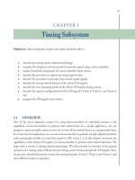
Objectives: After reading this chapter, the reader should be able to
•
describe the differences between serial and parallel communication,
•
provide definitions for key serial communications terminology,
•
describe the operation of the USART,
•
program the USART for basic transmission and reception,
•
describe the operation of the SPI,
•
program the SPI for basic transmission and reception, and
•
describe the purpose of the two-wire interface (TWI).
2.1 SERIAL COMMUNICATIONS
Microcontrollers must often exchange data with other microcontrollers or peripheral devices. Data
may be exchanged by using parallel or serial techniques. With parallel techniques, an entire byte of
data is typically sent simultaneously from the transmitting device to the receiver device. Although
this is efficient from a time point of view, it requires eight separate lines for the data transfer [1].
In serial transmission, a byte of data is sent a single bit at a time. Once 8 bits have been
received at the receiver, the data byte is reconstructed. Although this is inefficient from a time point
of view, it only requires a line (or two) to transmit the data.
The ATmega16 is equipped with a host of different serial communication subsystems,
including the serial USART, SPI, and TWI. What all of these systems have in common is the
serial transmission of data. Before discussing the different serial communication features aboard the
ATmega16, we review serial communication terminology.
2.2 SERIAL COMMUNICATION TERMINOLOGY
In this section, we review common terminology associated with serial communication.
26 ATMEL AVR MICROCONTROLLER PRIMER: PROGRAMMING AND INTERFACING
2.2.1 Asynchronous versus Synchronous Serial Transmission
In serial communications, the transmitting and receiving device must be synchronized to one
another and use a common data rate and protocol. Synchronization allows both the transmitter and
receiver to be expecting data transmission/reception at the same time. There are two basic methods
of maintaining ‘‘sync’’ between the transmitter and receiver: asynchronous and synchronous.
In an asynchronous serial communication system,such as the USART aboard the ATmega16,
framing bits are used at the beginning and end of a data byte. These framing bits alert the receiver
that an incoming data byte has arrived and also signals the completion of the data byte reception.
The data rate for an asynchronous serial system is typically much slower than the synchronous
system, but it only requires a single wire between the transmitter and receiver.
A synchronous serial communication system maintains ‘‘sync’’ between the transmitter and
receiver by employing a common clock between the two devices. Data bits are sent and received on
the edge of the clock. This allows data transfer rates higher than with asynchronous techniques but
requires two lines, data and clock, to connect the receiver and transmitter.
2.2.2 Baud Rate
Data transmission rates are typically specified as a baud or bits per second rate. For example, 9600
baud indicates data are being transferred at 9600 bits per second.
2.2.3 Full Duplex
Often, serial communication systems must both transmit and receive data. To do both transmission
and reception simultaneously requires separate hardware for transmission and reception. A single
duplex system has a single complement of hardware that must be switched from transmission
to reception configuration. A full duplex serial communication system has separate hardware for
transmission and reception.
2.2.4 Nonreturn to Zero Coding Format
There are many different coding standards used within serial communications. The important point
is the transmitter and receiver must use a common coding standard so data may be interpreted
correctly at the receiving end. The Atmel ATmega16 [2] uses a nonreturn to zero coding standard.
In nonreturn to zero, coding a logic 1 is signaled by a logic high during the entire time slot allocated
for a single bit, whereas a logic 0 is signaled by a logic low during the entire time slot allocated for
a single bit.
SERIAL COMMUNICATIONSUBSYSTEM 27
2.2.5 The RS-232 Communication Protocol
When serial transmission occurs over a long distance, additional techniques may be used to ensure
data integrity. Over long distances, logic levels degrade and may be corrupted by noise. At the
receiving end, it is difficult to discern a logic high from a logic low. The RS-232 standard has
been around for some time. With the RS-232 standard (EIA-232), a logic 1 is represented with
a
−12
-VDC level, whereas a logic 0 is represented by a +12-VDC level. Chips are commonly
available (e.g., MAX232) that convert the 5- and 0-V output levels from a transmitter to RS-232-
compatible levels and convert back to 5- and 0-V levels at the receiver. The RS-232 standard also
specifies other features for this communication protocol.
2.2.6 Parity
To further enhance data integrity during transmission, parity techniques may be used. Parity is an
additional bit (or bits) that may be transmitted with the data byte. The ATmega16 uses a single
parity bit. With a single parity bit, a single-bit error may be detected. Parity may be even or odd.
In even parity, the parity bit is set to 1 or 0, such that the number of 1’s in the data byte including
the parity bit is even. In odd parity, the parity bit is set to 1 or 0, such that the number of 1’s
in the data byte including the parity bit is odd. At the receiver, the number of bits within a data
byte including the parity bit are counted to ensure that parity has not changed, indicating an error,
during transmission.
2.2.7 American Standard Code for Information Interchange
The American Standard Code for Information Interchange (ASCII) is a standardized seven-bit
method of encoding alphanumeric data. It has been in use for many decades, so some of the
characters and actions listed in the ASCII table are not in common use today. However, ASCII
is still the most common method of encoding alphanumeric data. The ASCII code is provided
in Figure 2.1. For example, the capital letter ‘‘G’’ is encoded in ASCII as 0x47. The ‘‘0x’’ symbol
indicates the hexadecimal number representation. Unicode is the international counterpart of
ASCII. It provides standardized 16-bit encoding format for the written languages of the world.
ASCII is a subset of Unicode. The interested reader is referred to the Unicode home page website
at www.unicode.org for additional information on this standardized encoding format.
2.3 SERIAL USART
The serial USART provide for full duplex (two-way) communication between a receiver and
transmitter. This is accomplished by equipping the ATmega16 with independent hardware for the
transmitter and receiver. The USART is typically used for asynchronous communication. That is,
there is not a common clock between the transmitter and receiver to keep them synchronized with
28 ATMEL AVR MICROCONTROLLER PRIMER: PROGRAMMING AND INTERFACING
0x_0
0x_1
0x_2
0x_3
0x_4
0x_5
0x_6
0x_7
0x_8
0x_9
0x_A
0x_B
0x_C
0x_D
0x_E
0x_F
0x0_
NUL
SOH
STX
ETX
EOT
ENQ
ACK
BEL
BS
HT
LF
VT
FF
CR
SO
SI
0x1_
DLE
DC1
DC2
DC3
DC4
NAK
SYN
ETB
CAN
EM
SUB
ESC
FS
GS
RS
US
0x2_
SP
!
“
#
$
%
&
‘
(
)
*
+
‘
-
.
/
0x3_
0
1
2
3
4
5
6
7
8
9
:
;
<
=
>
?
0x4_
@
A
B
C
D
E
F
G
H
I
J
K
L
M
N
O
0x5_
P
Q
R
S
T
U
V
W
X
Y
Z
[
\
]
^
_
0x6_
`
a
b
c
d
e
f
g
h
i
j
k
l
m
n
o
0x7_
p
q
r
s
t
u
v
w
x
y
z
{
|
}
~
DEL
Most significant digit
Least significant digit
FIGURE 2.1: ASCII Code. The ASCII code is used to encode alphanumeric characters. The ‘‘0x’’
indicates hexadecimal notation in the C programming language.
one another. To maintain synchronization between the transmitter and receiver, framing start and
stop bits are used at the beginning and end of each data byte in a transmission sequence. The
Atmel USART also has synchronous features. Space does not permit a discussion of these USART
enhancements.
The ATmega16 USART is quite flexible. It has the capability to be set to a variety of data
transmissionor baud (bits per second) rates. The USART may also be set for data bit widths of 5 to 9
bits with one or two stop bits. Furthermore, the ATmega16 is equipped with a hardware-generated
parity bit (even or odd) and parity check hardware at the receiver. A single parity bit allows for
the detection of a single bit error within a byte of data. The USART may also be configured to
operate in a synchronous mode. We now discuss the operation, programming, and application of
the USART. Because of space limitations, we cover only the most basic capability of this flexible
and powerful serial communication system.
2.3.1 System Overview
The block diagram for the USART is provided in Figure 2.2. The block diagram may appear a
bit overwhelming, but realize there are four basic pieces to the diagram: the clock generator, the
SERIAL COMMUNICATIONSUBSYSTEM 29
FIGURE 2.2: Atmel AVR ATmega16 USART block diagram. Figure used with permission of Atmel.
transmission hardware, the receiver hardware, and three control registers (UCSRA, UCSBR, and
UCSRC). We discuss each in turn.
2.3.1.1 USART Clock Generator. The USART Clock Generator provides the clock source for
the USART system and sets the baud rate for the USART. The baud rate is derived from the
30 ATMEL AVR MICROCONTROLLER PRIMER: PROGRAMMING AND INTERFACING
overall microcontroller clock source. The overall system clock is divided by the USART baud rate
registers UBRR[H:L] and several additional dividers to set the baud rate. For the asynchronous
normal mode (U2X bit = 0), the baud rate is determined using the following expression:
baud rate=(system clock frequency)/(2(UBRR + 1)),
where UBRR is the content of the UBRRH and UBRRL registers (0--4095). Solving for UBRR
yields
UBRR=((system clock generator)/(16
×
baud rate))- 1
2.3.1.2 USART Transmitter. The USART transmitter consists of a Transmit Shift Register.
The data to be transmitted are loaded into the Transmit Shift Register via the USART I/O Data
Register (UDR). The start and stop framing bits are automatically appended to the data within the
Transmit Shift Register. The parity is automatically calculated and appended to the Transmit Shift
Register. Data are then shifted out of the Transmit Shift Register via the TxD pin a single bit at
a time at the established baud rate. The USART transmitter is equipped with two status flags: the
USART Data Register Empty (UDRE) and the transmit complete (TXC) flags. The UDRE flag
sets when the transmit buffer is empty, indicating it is ready to receive new data. This bit should be
written to a zero when writing the USART Control and Status Register A (UCSRA). The UDRE
bit is cleared by writing to the UDR. The TXC flag bit is set to logic 1 when the entire frame in
the Transmit Shift Register has been shifted out and there are no new data currently present in the
transmit buffer. The TXC bit may be reset by writing a logic 1 to it.
2.3.1.3 USARTReceiver. The USART Receiver is virtually identical to the USART Transmitter
except for the direction of the data flow, which is reversed. Data are received a single bit at a time
via the RxD pin at the established baud rate. The USART receiver is equipped with the receive
complete (RXC) flag. The RXC flag is logic 1 when unread data exist in the receive buffer.
2.3.1.4 USART Registers. In this section, we discuss the register settings for controlling the
USART system. We have already discussed the function of the UDR and the USART baud rate
registers (UBRRH and UBRRL). Note: The USART Control and Status Register C (UCSRC)
and the USART baud rate register high (UBRRH) are assigned to the same I/O location in the
memory map (Figure 2.3). The URSEL bit (bit 7 of both registers) determines which register