Configurations
Bạn đang xem bản rút gọn của tài liệu. Xem và tải ngay bản đầy đủ của tài liệu tại đây (151.82 KB, 32 trang )
CHAPTER
7
Configurations
Configurations are a primary design unit used to bind
component instances to entities. For structural models,
configurations can be thought of as the parts list for the
model. For component instances, the configuration specifies
from many architectures for an entity which architecture
to use for a specific instance. When the configuration for
an entity-architecture combination is compiled into the
library, a simulatable object is created.
Configurations can also be used to specify generic values
for components instantiated in the architecture configured
by the configuration. This mechanism, for example, pro-
vides a late-binding capability for delay values. Delay values
calculated from a physical layout tool, such as a printed
circuit board design system or a gate array layout system,
can be inserted in a configuration to provide a simulation
model with actual delays in the design.
If the designer wants to use a component in an archi-
tecture that has different port names from the architec-
ture component declaration, the new component can have
its ports mapped to the appropriate signals. With this
functionality, libraries of components can be mixed and
matched easily.
7
Chapter Seven
174
The configuration can also be used to provide a very fast substitution
capability. Multiple architectures can exist for a single entity. One archi-
tecture might be a behavioral model for the entity, while another architec-
ture might be a structural model for the entity. The architecture used in
the containing model can be selected by specifying which architecture to
use in the configuration, and recompiling only the configuration. After
compilation, the simulatable model uses the specified architecture.
Default Configurations
The simplest form of explicit configuration is the default configuration.
(The simplest configuration is none at all in which the last architecture
compiled is used for an entity.) This configuration can be used for models
that do not contain any blocks or components to configure. The default
configuration specifies the configuration name, the entity being configured,
and the architecture to be used for the entity. Following is an
example of two default configurations shown by configurations
big_count
and
small_count
:
LIBRARY IEEE;
USE IEEE.std_logic_1164.ALL;
ENTITY counter IS
PORT(load, clear, clk : IN std_logic;
PORT(data_in : IN INTEGER;
PORT(data_out : OUT INTEGER);
END counter;
ARCHITECTURE count_255 OF counter IS
BEGIN
PROCESS(clk)
VARIABLE count : INTEGER := 0;
BEGIN
IF clear = ‘1’ THEN
count := 0;
ELSIF load = ‘1’ THEN
count := data_in;
ELSE
IF (clk’EVENT) AND (clk = ‘1’) AND
(clk’LAST_VALUE = ‘0’) THEN
IF (count = 255) THEN
count := 0;
ELSE
count := count + 1;
END IF;
175
Configurations
END IF;
END IF;
data_out <= count;
END PROCESS;
END count_255;
ARCHITECTURE count_64k OF counter IS
BEGIN
PROCESS(clk)
VARIABLE count : INTEGER := 0;
BEGIN
IF clear = ‘1’ THEN
count := 0;
ELSIF load = ‘1’ THEN
count := data_in;
ELSE
IF (clk’EVENT) AND (clk = ‘1’) AND
(clk’LAST_VALUE = ‘0’) THEN
IF (count = 65535) THEN
count := 0;
ELSE
count := count + 1;
END IF;
END IF;
END IF;
data_out <= count;
END PROCESS;
END count_64k;
CONFIGURATION small_count OF counter IS
FOR count_255
END FOR;
END small_count;
CONFIGURATION big_count OF counter IS
FOR count_64k
END FOR;
END big_count;
This example shows how two different architectures for a counter
entity can be configured using two default configurations. The entity for the
counter does not specify any bit width for the data to be loaded into
the counter or data from the counter. The data type for the input and output
data is
INTEGER
. With a data type of integer, multiple types of counters can
be supported up to the integer representation limit of the host computer
for the VHDL simulator.
The two architectures of entity counter specify two different-sized
counters that can be used for the entity. The first architecture,
count_255
,
specifies an 8-bit counter. The second architecture,
count_64k
, specifies a
Chapter Seven
176
16-bit counter. The architectures specify a synchronous counter with a
synchronous
load
and
clear
. All operations for the device occur with respect
to the clock.
Each of the two configurations for the entity specifies a different
architecture for the counter entity. Let’s examine the first configuration
in more detail. The configuration design unit begins with the keyword
CONFIGURATION
and is followed by the name of the configuration. In this
example, the name of the configuration is
small_count
. The keyword
OF
precedes the name of the entity
BEGIN
configured (counter). The next line
of the configuration starts the block configuration section. The keyword
FOR
is followed by a name of the architecture to use for the entity being
configured or the name of the block of the architecture that will be config-
ured. Any component or block configuration information then exists
between the
FOR ARCHITECTURE
clause and the matching
END FOR
.
In this architecture, there are no blocks or components to configure;
therefore, the block configuration area from the
FOR
clause to the
END
FOR
clause is empty, and the default is used. The configuration is called
the default configuration, because the default is used for all objects in
the configuration.
The first configuration is called
small_count
and binds architecture
count_255
with entity
counter
to form a simulatable object. The second
configuration binds architecture
count_64k
with entity
counter
and
forms a simulatable object called
big_count
.
Component Configurations
In this section, we discuss how architectures that contain instantiated
components can be configured. Architectures that contain other compo-
nents are called structural architectures. These components are config-
ured through component configuration statements.
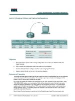
Let’s first look at some very simple examples of component configura-
tions, and then at some progressively more complex examples. The first
example is a simple 2 to 4 decoder device. Figure 7-1 shows the symbol
for the decoder, and Figure 7-2 shows the schematic.
The components used in the design are defined using the VHDL descrip-
tion shown here:
LIBRARY IEEE;
USE IEEE.std_logic_1164.ALL;
177
Configurations
Decode
A
B
EN
Q0
Q1
Q2
Q3
Figure 7-1
Symbol for Decoder
Example.
ENTITY inv IS
PORT( a : IN std_logic;
PORT( b : OUT std_logic);
END inv;
ARCHITECTURE behave OF inv IS
BEGIN
b <= NOT(a) AFTER 5 ns;
END behave;
CONFIGURATION invcon OF inv IS
FOR behave
END FOR;
END invcon;
LIBRARY IEEE; USE IEEE.std_logic_1164.ALL;
ENTITY and3 IS
PORT( a1, a2, a3 : IN std_logic;
PORT( o1 : OUT std_logic);
END and3;
ARCHITECTURE behave OF and3 IS
BEGIN
o1 <= a1 AND a2 AND a3 AFTER 5 ns;
END behave;
CONFIGURATION and3con OF and3 IS
FOR behave
END FOR;
END and3con;
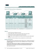
Next, the entity and architecture for decode are shown:
LIBRARY IEEE; USE IEEE.std_logic_1164.ALL;
ENTITY decode IS
PORT( a, b, en : IN std_logic;
PORT( q0, q1, q2, q3 : OUT std_logic);
END decode;
Chapter Seven
178
EN
A
B
Q0
Q1
Q2
Q3
nota
notb
Figure 7-2
Gate Level Schematic
for Decoder.
ARCHITECTURE structural OF decode IS
COMPONENT inv
PORT( a : IN std_logic;
PORT( b : OUT std_logic);
END COMPONENT;
COMPONENT and3
PORT( a1, a2, a3 : IN std_logic;
PORT( o1 : OUT std_logic);
END COMPONENT;
SIGNAL nota, notb : std_logic;
BEGIN
I1 : inv
PORT MAP(a, nota);
I2 : inv
PORT MAP(b, notb);
A1 : and3
PORT MAP(nota, en, notb, Q0);
A2 : and3
PORT MAP(a, en, notb, Q1);
A3 : and3
179
Configurations
PORT MAP(nota, en, b, Q2);
A4 : and3
PORT MAP(a, en, b, Q3);
END structural;
When all of the entities and architectures have been compiled into the
working library, the circuit can be simulated. The simulator uses the last
compiled architecture to build the executable design for the simulator
because it is the default. Using the last compiled architecture for an
entity to build the simulator works fine in a typical system, until more
than one architecture exists for an entity. Then it can become confusing
as to which architecture was compiled last. A better method is to specify
exactly which architecture to use for each entity. The component configu-
ration binds architectures to entities.
Two different styles can be used for writing a component configura-
tion for an entity. The lower-level configuration style specifies lower-
level configurations for each component, and the entity-architecture
style specifies entity-architecture pairs for each component. The word
style is used to describe these two different configurations because
there is no hard-and-fast rule about how to use them. Lower-level con-
figurations can be mixed with entity-architecture pairs, creating a
mixed-style configuration.
Lower-Level Configurations
Let’s examine the configuration for the lower-level configuration style
first. Following is an example of such a configuration for the decode entity:
CONFIGURATION decode_llcon OF decode IS
FOR structural
FOR I1 : inv USE CONFIGURATION WORK.invcon;
END FOR;
FOR I2 : inv USE CONFIGURATION WORK.invcon;
END FOR;
FOR ALL : and3 USE CONFIGURATION WORK.and3con;
END FOR;
END FOR;
END decode_llcon;
Chapter Seven
180
This configuration specifies which configuration to use for each compo-
nent in architecture
structural
of entity
decode
. The specified lower-level
configuration must already exist in the library for the current configura-
tion to compile. Each component being configured has a
FOR
clause to begin
the configuration and an
END FOR
clause to end the configuration specifi-
cation for the component. Each component can be specified with the
component instantiation label directly, as shown for component
I1
,or
with an
ALL
or
OTHERS
clause as shown by the
and3
components.
After the component is uniquely specified by label or otherwise, the
USE
CONFIGURATION
clause specifies which configuration to use for this
instance of the component. In the preceding example, the configuration
specification for component
I1
uses the configuration called
invcon
, from
the working library. For configuration
decode_llcon
to compile, configu-
ration
invcon
must have been already compiled into library
WORK
.
Notice that the names of the entities, architectures, and configurations
reflect a naming convention. In general, this is a good practice. It helps
distinguish the different types of design units from one another when they
all exist in a library.
The advantage of this style of configurations is that most configura-
tions are easy to write and understand. The disadvantage is not being
able to change the configuration of a lower-level component, without
implementing a two-step or more process of recompilation when hierarchy
levels increase.
Entity-Architecture Pair Configuration
The other style of component configurations is the entity-architecture pair
style. Following is an example of a configuration that uses the same
entity and architectures as the previous example:
CONFIGURATION decode_eacon OF decode IS
FOR structural
FOR I1 : inv USE ENTITY WORK.inv(behave);
END FOR;
FOR OTHERS : inv USE ENTITY WORK.inv(behave);
END FOR;
FOR A1 : and3 USE ENTITY WORK.and3(behave);
END FOR;
FOR OTHERS : and3 USE ENTITY WORK.and3(behave);
181
Configurations
END FOR;
END FOR;
END decode_eacon;
This configuration looks very similar to the lower-level configuration style
except for the
USE
clause in the component specification. In the previous
example, a configuration was specified, but in this style, an entity-
architecture pair is specified. The architecture is actually optional. If no
architecture is specified, the last compiled architecture for the entity is used.
Let’s take another look at the
FOR
clause for the first inverter,
I1
.In
the preceding example, the component is still specified by the label or by
an
ALL
or
OTHERS
clause. In this example, a
USE ENTITY
clause follows.
This clause specifies the name of the entity to use for this component.
The entity can have a completely different name than the component
being specified. The component name comes from the component decla-
ration in the architecture, while the entity name comes from the actual
entity that has been compiled in the library specified. Following the entity
is an optional architecture name that specifies which architecture to use
for the entity.
Notice that the
OTHERS
clause is used for the second inverter in this
example. The first inverter is configured from its label
I1
, and all com-
ponents that have not yet been configured are configured by the
OTHERS
clause. This capability allows component
I1
to use an architecture that
is different from the other components to describe its behavior. This
concept allows mixed-level modeling to exist. One component can be mod-
eled at the switch or gate level, and the other can be modeled at the be-
havior level.
To change the architecture used for a component with the first config-
uration,
decode_llcon
requires modifying the lower-level configuration
and recompiling, then recompiling any higher-level configurations that
depend on it. With the second configuration
decode_eacon
, changing the
architecture for a component involves modifying configuration
decode_eacon
and recompiling. No other configurations need be recompiled.
Port Maps
In the last two examples of component configurations, default mapping of
entity ports and component ports was used. When the port names for an
entity being configured to a component match the component port names,
Chapter Seven
182
no other mapping needs to take place. The default mapping causes the
ports to match. What happens when the component ports do not match
the entity being mapped to the component instance? Without any further
information, the compiler cannot figure out which ports to map to which
and produces an error. However, more information can be passed to the
compiler with the configuration port map clause.
The configuration port map clause looks exactly like the component
instantiation port map clause used in an architecture. The configuration
port map clause specifies which of the component ports map to the actual
ports of the entity. If the port names are different, then the port map
clause specifies the mapping.
Let’s change the port names of the
inv
component used in the previous
example and see what the effect is in the configuration:
LIBRARY IEEE;
USE IEEE.std_logic_1164.ALL;
ENTITY inv IS
PORT( x : IN std_logic;
PORT( y : OUT std_logic);
END inv;
ARCHITECTURE behave OF inv IS
BEGIN
y <= NOT(x) AFTER 5 ns;
END behave;
CONFIGURATION invcon OF inv IS
FOR behave
END FOR;
END invcon;
The entity and architecture for
decode
stays exactly the same, including
the component declaration. The configuration, however, needs to add the
port map clause, as shown in the following example:
CONFIGURATION decode_map_con OF decode IS
FOR structural
FOR I1 : inv USE ENTITY WORK.inv(behave);
PORT MAP( x => a, y => b );
END FOR;
FOR I2 : inv USE ENTITY WORK.inv(behave);
PORT MAP( x => a, y => b );
END FOR;
FOR ALL : and3 USE ENTITY WORK.and3(behave);
183
Configurations
END FOR;
END FOR;
END decode_map_con;
The port map clause maps the port names of the component declara-
tions, called the formal ports, to the port names of the entities from the
library. The term used for the ports of the entities from the library being
mapped are actuals. The ports are mapped using named association. The
rules for mapping ports using named association in the configuration port
map clause are the same rules as used in the component instantiation
port map clause.
In the preceding example, component declaration
inv
, port
a
, is mapped
to entity
inv
, port
x
, of the actual entity. Component declaration
inv
, port
b
, is mapped to entity
inv
, port
y
, of the actual entity. Using the configu-
ration port map clause can allow entities with completely different port
names to be mapped into existing architectures.
Mapping Library Entities
Not only can the ports be mapped with the configuration statement, but
entities from libraries can be mapped to components as well. This capa-
bility allows the names of components to differ from the actual entities
being mapped to them. The designer can easily switch the entity used for
each component in the architecture from one entity to another. This feature
allows the designer to map component instances to different entities.
Let’s assume that one AND gate of the decoder needs to be imple-
mented differently from the others due to physical constraints of the device.
For instance instead of using a 3-input AND gate, a 3-input AND gate is
built using 2-input AND gates. Let’s start with the 2-input AND gate model
as shown below:
LIBRARY IEEE; USE IEEE.std_logic_1164.ALL;
ENTITY and2 IS
PORT( a, b : in std_logic;
c : out std logic );
END and2;
ARCHITECTURE behave OF and2 IS
BEGIN
c <= a and b;
Chapter Seven
184
END behave;
CONFIGURATION and2con OF and2 IS
FOR behave
END FOR;
END and2con;
Two of these can be connected with the entity architecture shown be-
low to form a structural representation of the 3-input AND gate.
LIBRARY IEEE;
USE IEEE.std_logic_1164.ALL;
ENTITY
struc_and3 IS
PORT( I1, I2, I3 : IN std_logic;
PORT( O1 : OUT std_logic);
END struc_and3;
ARCHITECTURE structural OF struc_and3 IS
COMPONENT and2
PORT( a, b : in std logic;
c : out std logic );
END COMPONENT;
SIGNAL s1, s2 : std_logic;
BEGIN
X1 : and2
PORT MAP( a => I1, b => I2, c => s1 );
X2 : and2
PORT MAP( a => I3, b => s1, c => O1 );
END structural;
This architecture can then be configured with the following configuration:
CONFIGURATION and3strc con OF struc and3 IS
FOR structural
FOR X1 : and2 USE CONFIGURATION WORK.and2con;
END FOR;
FOR X2 : and2 USE CONFIGURATION WORK.and2con;
END FOR;
END FOR;
END and3strc con;
Now, configuration
decode_map_con
of entity
decode
, described earlier,
can be modified as follows: