Analog-to-Digital Conversion
Bạn đang xem bản rút gọn của tài liệu. Xem và tải ngay bản đầy đủ của tài liệu tại đây (7.84 MB, 24 trang )
41
CHAPTER 3
Analog-to-Digital Conversion
Objectives: After reading this chapter, the reader should be able to
•
explain the difference between analog and digital signals,
•
illustrate the ADC process,
•
assess the quality of ADC using the metrics of sampling rate, quantization levels, number
of bits used for encoding, and dynamic range,
•
design signal conditioning circuits to interface sensors with ADCs,
•
describe the key registers used during an ATmega16 ADC,
•
describe the steps to perform an ADC with the ATmega16, and
•
program the ATmega16 to perform an ADC.
A microcontroller is used to process information from the natural world, decide on a course
of action based on the information collected, and then issue control signals to implement the
decision. Because much of the information from the natural world is analog or continuous in nature
and the microcontroller is a digital or discrete-based processor, a method to convert an analog
signal to digital is required [1]. An ADC system performs this task, whereas a DAC performs the
conversion in the opposite direction. We will discuss both types of converters in this chapter.
In the first section, we present the fundamental concepts associated with the ADC process.
In the following section, we discuss the conversion process itself, followed by a presentation of
different hardware implementations of the process. Much of these early sections contain the same
material you will find in our text, Microcontroller Fundamentals for Engineers and Scientists.Wethen
review the basic features of the ATmega16 ADC system, followed by a system description and a
discussion of key ADC registers. We conclude our discussion of the ADC with several illustrative
code examples. We conclude the chapter with a discussion of the DAC process.
3.1 BACKGROUND THEORY
Before we discuss the ADC process, we need to familiarize you with underlying theories that
support the process. We start with some definitions on analog and digital signals.
42 ATMEL AVR MICROCONTROLLER PRIMER: PROGRAMMING AND INTERFACING
3.1.1 Analog versus Digital Signals
A signal is a collection of values representing the state of a physical variable. The collection can
be as small as only one value or can have as many values as you wish. In engineering, we usually
arrange the values in order, for example, over time or over a spatial axis, to display the information.
The time and spatial variables are called independent variables, because they are not affected by
the physical variables of interests. For example, we measure the temperature change over time. The
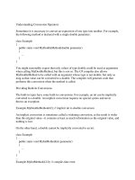
temperature measured is dependent on the time, not the other way around. Figure 3.1 shows an
altitude trajectory of a bird flying over a short period. The signal shows how the altitude of the bird
changes continuously.
Figure 3.2 shows a grayscale image of a six-legged robot. The image captured the light
intensities of the scene using a charge-coupled device camera. If we move from the left to the
right on the image and observe the intensity changes, we can find vertical edges by detecting signal
FIGURE 3.1: Altitude trajectory generated by a flying bird.
ANALOG-TO-DIGITAL CONVERSION 43
FIGURE 3.2: A photo of a walking robot.
intensity changes in the spatial axis. The same analysis can be performed as we move from the top
to the bottom of the image.
Analog signals are those whose physical variable values change continuously over their
independent variable. Most physical variables, your speech, movement of stars, and the music you
hear at a concert are analog signals, signals that we find all around us. Digital signals, on the
other hand, have their physical variables defined only for discrete instances over their independent
variables. Although it may look continuous to human eyes, the photo example shown in Figure 3.2
is a discrete signal because pixels that make up a camera image cannot capture all space within the
camera frame. The image is only a finite composition of intensity values seen by a discrete number
of pixels.
Digital signals are important because all signals represented in digital systems, computers,
and microcontrollers are in digital forms. The important task is how to faithfully represent analog
44 ATMEL AVR MICROCONTROLLER PRIMER: PROGRAMMING AND INTERFACING
signals using digital signals. For example, human voices must be converted to corresponding
digital signals before they can be routed by digital switching circuits in telephone communication
systems. Similarly, voice commands to robots must be converted to a digital form before robots can
understand the command.
As shown in the examples above, we live in an analog world; that is, physical variables are
analog signals. It is precisely this reason why the ADC is so very important in any digital systems
that interact with an analog environment.
3.1.2 Sampling, Quantization, and Encoding
In this subsection, we present three important processes associated with the ADC. We first start
with the subject of sampling. Imagine yourself as a photographer in an Olympic diving stadium.
Your job is taking a sequence of pictures of divers jumping off from a diving board 10 meters above
the surface of the diving pool. Your goal is to put the sequence of pictures together to reconstruct
the motion of each diver. The sequence of pictures makes up samples of divers’ motions. If a diver
tries a complex motion and you want to faithfully reconstruct his motion, you must take enough
pictures from the start to the end of the dive. If a diver makes a simple routine dive, you only need
to take a few pictures over the period of the dive. Two very differentcases of motions generated by a
diver is shown in Figure 3.3. The same time sequence is used to capture samples for both motions.
As can be seen from figure, frame (a) motion cannot be regenerated from the samples, whereas the
motion shown in frame (b) can clearly be reconstructed from the same number of samples used to
capture both motions.
Sampling is the process of taking ‘‘snapshots’’ of a signal over time. Naturally, when we
sample a signal, we want to sample it in an optimal fashion such that we can capture the essence
of the signal while minimizing the use of resources. In essence, we want to minimize the number
of samples while faithfully reconstructing the original signal from the samples. As can be deduced
from our discussion above, the rate of change in a signal determines the number of samples required
to faithfully reconstruct the signal, provided that all adjacent samples are captured with the same
sample timing intervals.
Harry Nyquist from Bell Laboratory studied the sampling process and derived a criterion
that determines the minimum sampling rate for any continuous analog signals. His, now famous,
minimum sampling rate is known as the Nyquist sampling rate, which states that one must sample
a signal at least twice as fast as the highest frequency content of the signal of interest. For example,
if we are dealing with the human voice signal that contains frequency components that span from
about 20 Hz to 4 kHz, the Nyquist sample theorem tells us that we must sample the signal at
least at 8 kHz, 8000 ‘‘snapshots’’ every second. Engineers who work for telephone companies
must deal with such issues. For further study on the Nyquist sampling rate, refer to Barrett
ANALOG-TO-DIGITAL CONVERSION 45
FIGURE 3.3: Two divers jumping off the platforms: (a) fast motion and (b) slow motion.
and Pack [2] listed in the References section. Sampling is important because when we want to
represent an analog signal in a digital system, such as a computer, we must use the appropriate
sampling rate to capture the analog signal for a faithful representation in digital systems.
Now that we understand the sampling process, let us move on to the second process of the
ADC, quantization. Each digital system has a number of bits, which it uses as the basic units to
represent data. A bit is the most basic unit where single binary information, 1 or 0, is represented.
A nibble is made up of 4 bits put together. A byte is 8 bits.
In the previous section, we tacitly avoided the discussion of the form of captured signal
samples. When a signal is sampled, digital systems need some means to represent the captured
46 ATMEL AVR MICROCONTROLLER PRIMER: PROGRAMMING AND INTERFACING
samples. The quantization of a sampled signal is how the signal is representedas one of quantization
level. Suppose you have a single bit to represent an incoming signal. You only have two different
numbers, 0 and 1. You may say that you can distinguish only low from high. Suppose you have
2 bits. You can represent four different levels, 00, 01, 10, and 11. What if you have 3 bits? You
now can represent eight different levels: 000, 001, 010, 011, 100, 101, 110, and 111. Think of it as
follows. When you had 2 bits, you were able to represent four different levels. If we add one more
bit, that bit can be 1 or 0, making the total possibilities 8. Similar discussion can lead us to conclude
that given n bits, we have
2
n
different numbers or levels one can represent.
Figure 3.4 shows how n bits are used to quantize a range of values. In many digital systems,
the incoming signals are voltage signals. The voltage signals are first obtained from physical signals
with the help of transducers, such as microphones, angle sensors, and infrared sensors. The voltage
signals are then conditioned to map their range with the input range of a digital system, typically
0to5V.InFigure3.4, n bits allow you to divide the input signal range of a digital system into
FIGURE 3.4: Quantization.
ANALOG-TO-DIGITAL CONVERSION 47
2
n
different quantization levels. As can be seen from the figure, higher quantization levels means
better mapping of an incoming signal to its true value. If we only had a single bit, we can only
represent levels 0 and 1. Any analog signal value in between the range had to be mapped either as
level 0 or level 1, not many choices. Now imagine what happens as we increase the number of bits
available for the quantization levels. What happens when the available number of bits is 8? How
many different quantization levels are available now? Yes, 256. How about 10, 12, or 14? Notice
also that as the number of bits used for the quantization levels increases for a given input range the
‘distance’ between two adjacent levels decreases with a factor of a polynomial.
Finally, the encoding process involves converting a quantized signal into a digital binary
number. Suppose again we are using 8 bits to quantize a sampled analog signal. The quantization
levels are determined by the 8 bits, and each sampled signal is quantized as one of 256 quantization
levels. Consider the two sampled signals shown in Figure 3.5. The first sample is mapped to
quantization level 2 and the second one is mapped to quantization level 198. Note the amount
FIGURE 3.5: Quantization with fewer bits.
48 ATMEL AVR MICROCONTROLLER PRIMER: PROGRAMMING AND INTERFACING
of quantization error introduced for both samples. Now consider Figure 3.5. The same signal is
sampled at the same time but quantized using a less number of bits. Note that the quantization
error is inversely proportional to the number of bits used to quantize the signal.
Once a sampled signal is quantized, the encoding process involves representing the quanti-
zation level with the available bits. Thus, for the first sample, the encoded sampled value is 0000
0001, whereas the encoded sampled value for the second sample is 1100 0110. As a result of the
encoding process, sampled analog signals are now represented as a set of binary numbers. Thus,
the encoding is the last necessary step to represent a sampled analog signal into its corresponding
digital form, shown in Figure 3.6.
3.1.3 Resolution and Data Rate
Resolution is a measure used to quantize an analog signal. In fact, resolution is nothing but the
‘‘distance’’ between two adjacent quantization levels we discussed earlier. Suppose again we have
FIGURE 3.6: Encoding.
ANALOG-TO-DIGITAL CONVERSION 49
a range of 5 V and 1 bit to represent an analog signal. The resolution in this case is 2.5 V, a
very poor resolution. You can imagine how your TV screen will look if you only had only two
levels to represent each pixel, black and white. The maximum error, called the resolution error,
is 2.5 V for the current case, 50% of the total range of the input signal. Suppose you now have
4 bits to represent quantization levels. The resolution now becomes 1.25 V, or 25% of the input
range. Suppose you have 20 bits for quantization levels. The resolution now becomes 4.77
×
10
−
6
,
9.54
×
10
−
5
% of the total range. The discussion we presented simply illustrates that as we increase
the available number of quantization levels within a range, the distance between adjacent levels
decreases, reducing the quantization error of a sampled signal. As the number grows, the error
decreases, making the representation of a sampled analog signal more accurate in the corresponding
digital form. The number of bits used for the quantization is directly proportional to the resolution
of a system. You now should understand the technical background when you watch high-definition
television broadcasting.
Now let us move onto the discussion of the data rate. The definition of the data rate is the
amount of data generated by a system per some time unit. Typically, the number of bits or the
number of bytes per second is used as the data rate of a system. We just saw that the more bits we
use for the quantization levels, the more accurate we can represent a sampled analog signal. Why
not use the maximum number of bits current technologies can offer for all digital systems, when
we convert analog signals to digital counterparts? It has to do with the cost involved. In particular,
suppose you are working for a telephone company and your switching system must accommodate
100,000 customers. For each individual phone conversation, suppose the company uses an 8-kHz
sampling rate and you are using 10 bits for the quantization levels for each sampled signal.
1
If all
customers are making out-of-town calls, what is the number of bits your switching system must
process to accommodate all calls? The answer will be 100,000
×
8000
×
10, or 8 billion bits per
every second! You will need some major computing power to meet the requirement. For such
reasons, when designers make decisions on the number of bits used for the quantization levels,
they must consider the computational burden the selection will produce on the computational
capabilities of a digital system versus the required system resolution.
You will also encounter the term dynamic range when you consider finding appropriate
ADCs. The dynamic range is a measure used to describe the signal to noise ratio. The unit used for
the measurement is decibel, which is the strength of a signal with respect to a reference signal. The
greater the decibel number, the stronger the signal is compared with a noise signal. The definition
of the dynamic range is 20 log 2
b
,whereb is the number of bits used to convert analog signals
1
For the sake of our discussion, we ignore other overheads involved in processing a phone call such as multiplexing,
demultiplexing, and serial-to-parallel conversion.