Laying Out GUIs and Setting Properties
Bạn đang xem bản rút gọn của tài liệu. Xem và tải ngay bản đầy đủ của tài liệu tại đây (559.32 KB, 70 trang )
3
Laying Out GUIs and
Setting Properties
Using GUIDE Templates (p. 3-2) Overview of GUIDE templates — simple GUIs that you
modify to create your own GUIs.
Using the Layout Editor (p. 3-9) Add and arrange objects in the figure window.
Selecting GUI Options (p. 3-25) Set the options for your GUI.
Aligning Components in the Layout
Editor (p. 3-34)
Align objects with respect to each other.
Setting Component Properties — The
Property Inspector (p. 3-40)
Inspect and set the property values of the GUI
components.
Viewing the Object Hierarchy — The
Object Browser (p. 3-56)
Observe a hierarchical list of the Handle Graphics objects
in the current MATLAB session.
Creating Menus — The Menu Editor
(p. 3-57)
Create menus for the window menu bar and context
menus for any component in your layout.
Setting the Tab Order — The Tab
Order Editor (p. 3-69)
Change the order in which GUI components are selected
by tabbing.
3
Laying Out GUIs and Setting Properties
3-2
Using GUIDE Templates
GUIDE provides several templates, which are simple examples that you can
modify to create your own GUIs. The templates are fully functional GUIs: their
callbacks are already programmed. You can view the code for these callbacks
to see how they work, and then modify the callbacks for your own purposes.
You can access the templates in two ways:
• Start GUIDE by entering
guide
at the MATLAB prompt.
• If GUIDE is already open, select
New
from the
File
menu in the Layout
Editor.
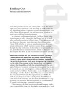
Starting GUIDE displays the
GUIDE Quick Start
dialog as shown in the
following figure.
The
Quick Start
dialog gives you two options:
• Select the
Open Existing GUI
tab and open a GUI that you have already
created.
• Select the
Create New GUI
tab and open one of the templates.
The preceding figure shows the
Quick Start
dialog with the
Create New GUI
tab selected. Selecting a template in the left pane displays a preview in the
Using GUIDE Templates
3-3
right pane. Clicking
OK
opens the GUI template in the Layout Editor. If you
select
Save on startup as
and type in name in the field to the right, GUIDE
saves the GUI before opening it in the Layout Editor. If you choose not to save
the GUI at this point, GUIDE prompts you to save it the first time you run the
GUI.
GUIDE provides four templates, which are described in the following sections:
• “Blank GUI” on page 3-3
• “GUI with Uicontrols” on page 3-4
• “GUI with Axes and Menu” on page 3-5
• “Modal Question Dialog” on page 3-6
To view the M-file for any of these templates, open the template in the Layout
Editor and click the M-file Editor icon on the toolbar.
Blank GUI
The blank GUI template displayed in the Layout Editor is shown in the
following figure.
3
Laying Out GUIs and Setting Properties
3-4
Select the blank GUI if the other templates are not suitable starting points for
the GUI you are creating, or if you prefer to start with an empty GUI.
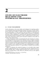
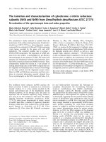
GUI with Uicontrols
The following figure shows the GUI with Uicontrols
template displayed in the
Layout Editor.
When you run the GUI by clicking the Run icon , the GUI appears as shown
in the following figure.
Using GUIDE Templates
3-5
When a user enters values for the density and volume of an object, and clicks
the
Calculate
button, the GUI calculates the mass of the object and displays
the result next to
Mass(D*V)
.
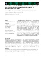
GUI with Axes and Menu
The GUI with axes and menu template is shown in the following figure.
When you run the GUI by clicking the Run icon on the toolbar, the GUI
displays a plot of five random numbers generated by the MATLAB
rand(5)
command, as shown in the following figure.
3
Laying Out GUIs and Setting Properties
3-6
You can select other plots in the pop-up menu. Clicking the
Update
button
displays the currently selected plot on the axes.
The GUI also has a
File
menu with three items:
• Selecting
Open
displays a dialog from which you can open files on your
computer.
• Selecting
executes the
printdlg
command, which opens the
dialog:
printdlg(handles.figure1)
Note that
handles.figure1
contains the current plot. Clicking
Yes
in the
dialog prints the plot.
• Selecting
Close
closes the GUI.
Modal Question Dialog
The modal question dialog
template displayed in the Layout Editor is shown in
the following figure.
Using GUIDE Templates
3-7
Running the GUI displays the dialog shown in the following figure:
The GUI returns the text string
Yes
or
No
, depending on which button you
press. The GUI is blocking, which means that the current M-file stops
executing until the GUI restores execution. You can make a GUI blocking by
adding the following command to the opening function:
uiwait(handles.figure1);
3
Laying Out GUIs and Setting Properties
3-8
To restore access to other MATLAB windows once a button is clicked, add the
following command to callbacks for both the
Yes
and
No
push buttons:
uiresume(handles.figure1);
The GUI is also modal, which means that the user cannot interact with other
MATLAB windows until clicking one of the buttons. See “Using Modal Figure
Windows” on page 4-38 for more information on making a GUI modal.
Select this template if you want your GUI to return a string or to be modal.
See “Example: Using the Modal Dialog to Confirm an Operation” on page 4-40
for an example of using this template with another GUI.
Using the Layout Editor
3-9
Using the Layout Editor
The Layout Editor enables you to select GUI components from the component
palette, at the left side of Layout Editor, and arrange them in the layout area,
to the right. When you click the
Run
icon , the functioning GUI appears
outside the Layout Editor.
This section covers the following topics:
• “Starting the Layout Editor” on page 3-9
• “Selecting Components from the Component Palette” on page 3-10
• “Adding Components to the Layout Area” on page 3-13
• “Working with Components in the Layout Area” on page 3-16
• “Running the GUI” on page 3-19
• “Saving the Layout” on page 3-21
• “Renaming GUI Files” on page 3-21
• “Displaying the GUI” on page 3-22
• “Layout Editor Preferences” on page 3-22
• “Layout Editor Context Menus” on page 3-23
Starting the Layout Editor
To start the Layout Editor, first open the GUIDE Quick Start dialog by
entering
guide
at the MATLAB prompt. Click
OK
in the dialog to open a blank
GUI template in the Layout Editor, as shown in the following picture.
3
Laying Out GUIs and Setting Properties
3-10
If you want to load an existing GUI for editing, type
guide filename.fig
or use
Open
from the
File
menu on the Layout Editor.
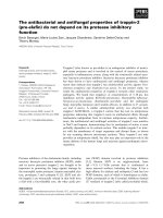
Selecting Components from the Component Palette
The component palette at the left of the Layout Editor contains the components
that you can add to your GUI. This section describes these components.
Component
Palette
Alignment Tool Menu Editor Property Inspector
Run
Layout Area
Figure Resize Tab
Undo
Redo
Object BrowserM-file EditorTab Order Editor
Using the Layout Editor
3-11
After selecting the components for your GUI and placing them in the layout
area, you need to set their properties and program their callbacks. The
following sections describe how to do this:
• “Setting Component Properties — The Property Inspector” on page 3-40
• “Programming Callbacks for GUI Components” on page 4-8
Push Button
Push buttons generate an action when clicked. For example, an
OK
button
might close a dialog box and apply settings. When you click a push button, it
appears depressed; when you release the mouse, the button appears raised and
its callback executes.
Toggle Button
Toggle buttons generate an action and indicate whether they are turned on or
off. When you click a toggle button, it appears depressed, showing that it is on.
When you release the mouse button, the toggle button’s callback executes.
However, unlike a push button, the toggle button remains depressed until you
click the toggle button a second time. When you do so, the button returns to the
raised state, showing that it is off, and again executes its callback.
Radio Button
Radio buttons are similar to check boxes, but are typically mutually exclusive
within a group of related radio buttons. That is, you can select only one button
at any given time. To activate a radio button, click the mouse button on the
object. The display indicates the state of the button.
Check Box
Check boxes generate an action when checked and indicate their state as
checked or not checked. Check boxes are useful when providing the user with
a number of independent choices that set a mode, for example, displaying a
toolbar or generating callback function prototypes.
Edit Text
Edit text controls are fields that enable users to enter or modify text strings.
Use edit text when you want text as input. The
String
property contains the
text entered by the user. The callback executes when you press
Enter
for a
3
Laying Out GUIs and Setting Properties
3-12
single-line edit text,
Ctl+Enter
for a multi-line edit text, or the focus moves
away.
Static Text
Static text controls display lines of text. Static text is typically used to label
other controls, provide directions to the user, or indicate values associated with
a slider. Users cannot change static text interactively and there is no way to
invoke the callback routine associated with it.
Slider
Sliders accept numeric input within a specific range by enabling the user to
move a sliding bar, which is called a slider or thumb. Users move the slider by
pressing the mouse button and dragging the slider, by clicking in the trough,
or by clicking an arrow. The location of the slider indicates a percentage of the
specified range.
List Box
List boxes display a list of items and enable users to select one or more items.
Pop-Up Menu
Pop-up menus open to display a list of choices when users click the arrow.
Axes
Axes enable your GUI to display graphics (e.g., graphs and images). Like all
graphics objects, axes have properties that you can set to control many aspects
of its behavior and appearance. See “Axes Properties” in the MATLAB
Graphics documentation for more information on axes objects.
Panel
Panels group GUI components. Panels can make a user interface easier to
understand by visually grouping related controls. A panel can have a title and
various borders.
Panel children can be panels and button groups as well as axes and user
interface controls. The position of each component within a panel is interpreted
relative to the panel. If you move the panel, its children move with it and
maintain their positions on the panel.
Using the Layout Editor
3-13
Button Group
Button groups are like panels but can be used to manage exclusive selection
behavior for radio buttons and toggle buttons.
For radio buttons and toggle buttons that are managed by a button group, you
must include the code to control them in the button group’s
SelectionChangeFcn
callback function, not in the individual uicontrol
Callback
functions. A button group overwrites the
Callback
properties of
radio buttons and toggle buttons that it manages.
ActiveX Component
ActiveX components enable you to display ActiveX controls in your GUI. See
“Adding an ActiveX Control to a GUI” on page 4-17 for an example.
Note Only figures can have child ActiveX components. Panels and button
groups cannot.
ActiveX components are available only on the Microsoft Windows platform.
Adding Components to the Layout Area
You can place a component in the layout area in one of these ways:
• Drag the component from the component palette into the layout area and
drop it.
• Select the component in the component palette. The cursor changes to a
cross.
- Place the cursor in the layout area where you want the upper-left corner
of the component to be and click.
- Place the cursor in the layout area where you want the upper-left corner
of the component to be, then set the size of the control by clicking and
dragging the cursor to the lower-left corner before releasing the mouse
button.
This is an example of a GUI in the Layout Editor. Note that components in the
Layout Editor are not active. “Running the GUI” on page 3-19describes how to
generate a functioning GUI.
3
Laying Out GUIs and Setting Properties
3-14
Adding a Component to a Panel or Button Group
To add a component to a panel or button group, select the component in the
component palette then move the cursor over the desired panel or button
group. The position of the cursor determines the component’s parent. Notice
that GUIDE highlights the potential parent as shown in the following figure.
The highlight indicates that if you drop the component or click the cursor, the
component will be a child of the highlighted panel or button group.
Using the Layout Editor
3-15
If the component is not entirely contained in the panel or button group, it
appears to be clipped in the layout editor.
When you run the GUI, the entire component is displayed and straddles the
panel or button group border. The component is nevertheless a child of the
panel and behaves accordingly.
Highlight
Cursor
3
Laying Out GUIs and Setting Properties
3-16
You can use the Object Browser to determine the child objects of a panel or
button group. “Viewing the Object Hierarchy — The Object Browser” on
page 3-56 tells you how.
Adding an ActiveX Control
When you drag an ActiveX component from the component palette into the
layout area, GUIDE opens a dialog that lists all the registered ActiveX controls
on your system. When you select an ActiveX control and click
Create
, the
control appears as a small box in the Layout Editor.
Note The available ActiveX controls vary on different systems. An ActiveX
control can be the child of a figure only. It cannot be the child of a panel or
button group.
Working with Components in the Layout Area
This topic provides basic information about selecting, moving, copying, and
deleting components in the layout area.
Other topics that may be of interest are
• “Aligning Components in the Layout Editor” on page 3-34
• “Front-to-Back Positioning” on page 3-38
• “Setting the Tab Order — The Tab Order Editor” on page 3-69
Using the Layout Editor
3-17
Selecting Components
You can select components in the layout area in the following ways.
• Click a single component to select it.
• Press
Ctrl+A
to select all child objects of the figure. This does not select
components that are child objects of panels or button groups.
• Click and drag the cursor to create a rectangle that encloses the components
you want to select. If the rectangle encloses a panel or button group, only the
panel or button group is selected, not its children. If the rectangle encloses
part of a panel or button group, only the components within the rectangle
that are child objects of the panel or button group are selected.
• Select multiple components using the
Shift
and
Ctrl
keys.
Note You can select multiple components only if they have the same parent.
Use the Object Browser to determine the child objects of a figure, panel, or
button group. “Viewing the Object Hierarchy — The Object Browser” on
page 3-56 tells you how.
Moving Components
Select one or more components that you want to move, then do one of the
following:
• Drag the selected components to the desired position and drop them. You can
move components from the figure into a panel or button group. You can move
components from a panel or button group into the figure or into another
panel or button group.
The position of the cursor when you drop the components determines the
parent of all the selected components. Look for the highlight as described in
“Adding a Component to a Panel or Button Group” on page 3-14.
In some cases, one or more of the selected components may lie outside its
parent’s boundary. Such a component is not visible in the Layout Editor but
can be selected by dragging a rectangle that encloses it. It is visible, however,
in the active GUI.
• Press and hold the arrow keys until the components have moved to the
desired position. Note that the components remain children of the figure,
3
Laying Out GUIs and Setting Properties
3-18
panel, or button group from which you move them, even if they move outside
its boundaries.
Copying, Cutting, and Clearing Components
Use standard menu and pop-up menu commands, toolbar icons, keyboard keys,
and shortcut keys to copy, cut, and clear components.
Copying.
Copying places a copy of the selected components on the clipboard. A
copy of a panel or button group includes its children.
Cutting.
Cutting places a copy of the selected components on the clipboard and
deletes them from the layout area. If you cut a panel or button group, you also
cut all its children.
Clearing.
Clearing deletes the selected components from the layout area. It does
not place a copy of the components on the clipboard.
Pasting and Duplicating Components
Pasting.
Use standard menu and pop-up menu commands, toolbar icons, and
short-cut keys to paste components. GUIDE pastes the contents of the
clipboard to the upper-left corner (location [0,0]) of the
• Figure, if no components are selected
• Parent of a selected component, if the component is not a panel or button
group
• Panel or button group, if only one panel or button group is selected
• Parent of two or more selected components, even if one is a panel or button
group
Consecutive pastes place each copy to the lower right of the last one.
Duplicating.
Select one or more components that you want to duplicate, then do
one of the following:
• Copy and paste the selected components as described above.
• Select
Duplicate
from the
Edit
menu or the pop-up menu.
Duplicate
places
the copy to the lower right of the original.
Using the Layout Editor
3-19
• Right-click and drag the component to the desired location. The position of
the cursor when you drop the components determines the parent of all the
selected components. Look for the highlight as described in “Adding a
Component to a Panel or Button Group” on page 3-14.
Running the GUI
To run the GUI you design in the Layout Editor, select
Run
in the
Tools
menu
or click the
Run
icon on the toolbar.
When you run a GUI, the following occurs:
• GUIDE first prompts you to save both the M-file and FIG-file with the dialog
shown in the following figure.
• If you click
Yes
and you have not saved the GUI previously, GUIDE opens a
Save As
dialog box so you can select a name for both the FIG-file and the
M-file GUIDE generates.
• When you click
Save
in the
Save As
dialog box, GUIDE saves the FIG-file
with the same name as the M-file, but with a
.fig
extension.
• If an M-file with the same name exists, GUIDE prompts you to replace or
append to the existing code in the M-file.
3
Laying Out GUIs and Setting Properties
3-20
Replace
— writes over the existing file.
Append
— inserts new callbacks for components added since the last save
and make changes to the code based on change made from the Application
Options dialog.
• If the directory in which you saved the GUI is not on the MATLAB path,
GUIDE opens a dialog box with three options, as shown in the following
figure.
Change MATLAB current directory
— changes the MATLAB current
directory to the directory where you saved the GUI.
Add directory to the top of the MATLAB path
— adds the directory where
you saved the GUI to the top of the MATLAB path.
Add directory to the bottom of the MATLAB path
— adds the directory
where you saved the GUI to the bottom of the MATLAB path.
• MATLAB executes the M-file to display the GUI. The options specified in the
Application Options dialog are functional in the GUI.
Using the Layout Editor
3-21
Note GUIDE automatically saves both the M-file and the FIG-file when you
run the GUI.
Saving the Layout
Once you have created the GUI layout, you can save it as a FIG-file (a binary
file that saves the contents of a figure) using the
Save
or
Save As
item from the
File
menu. GUIDE generates the M-file automatically when you save or run
the figure.
Renaming GUI Files
Use
Save As
from the Layout Editor
File
menu to rename the GUI FIG-file.
GUIDE renames the FIG-file and the GUI M-file and also resets the callback
properties to properly execute the callbacks.
Exporting a GUI to a Single M-File
You can export a GUI from GUIDE to a single M-file that does not require a
FIG-file. This enables you to
• View the layout code for the GUI
• Run the GUI in MATLAB 6.1
Note If the GUI contains a panel or a button group, you will not be able to
run it in MATLAB versions earlier than 7.0.
To export your GUI, do the following steps:
1
Save the GUI in GUIDE, if you have not already done so.
2
Select
Export
from the
File
menu. If you changed the GUI since you last
saved it, this opens a dialog informing you that exporting will save changes
to your figure and M-file, and asking if you want to continue.
3
Click
OK
in the confirmation dialog.
3
Laying Out GUIs and Setting Properties
3-22
4
Save the exported M-file in the
Save As
dialog. By default, GUIDE gives the
exported M-file the name of the GUI M-file with
_export
appended.
Note If you save a large data set in the GUI figure or in a uicontrol, GUIDE
might also export a MAT-file containing the data in addition to exporting an
M-file. For example, the data could be saved in a figure or uicontrol
UserData
property, or in a figure
Colormap
property. The name of the MAT-file is the
same as the exported M-file except for the extension
.mat
.
Displaying the GUI
You can display the GUI figure using the
openfig
,
open
, or
hgload
command.
These commands load FIG-files into the MATLAB workspace. Note that the
displayed GUI is not active.
Generally, however, you launch your GUI by executing the M-file that GUIDE
generates. This M-file contains the commands to load the GUI and provides a
framework for the component callbacks. See “Configuring the GUI M-File” on
page 3-25 for more information.
Layout Editor Preferences
You can set preferences for the Layout Editor by selecting
Preferences
from
the
File
menu.
Using the Layout Editor
3-23
Layout Editor Context Menus
When working in the Layout Editor, you can select an object with the left
mouse button and then click the right button to display a context menu.
Like the
View
menu in the Layout Editor, these context menus enable you to
add a callback subfunction to your GUI M-file for any of the object properties
that define callback routines. See “Callback Properties” on page 3-51 for more
information.
Figure Context Menus
The following picture shows the context menu associated with a figure object.
Note that all properties that define callback routines for figures are listed in
the submenu.
3
Laying Out GUIs and Setting Properties
3-24
Component Context Menus
The following picture shows the context menu associated with user interface
control components, as well as with axes, panels, and button groups. The
callback properties listed in the
View Callbacks
submenu differ for different
components.
Selecting GUI Options
3-25
Selecting GUI Options
After opening a new GUI template in the Layout Editor, but before saving the
GUI, you can configure the GUI using the
GUI Options
dialog. Access the
dialog by selecting
GUI Options
from the Layout Editor
Tools
menu.
Configuring the GUI M-File
The
GUI Options
dialog enables you to select whether you want GUIDE to
generate only a FIG-file for your layout or both a FIG-file and an M-file. You
can also select a number of different behaviors for your GUI.
The following sections describe the options in this dialog:
• “Resize Behavior” on page 3-26
• “Command-Line Accessibility” on page 3-27
• “Generate FIG-File and M-File” on page 3-29
• “Generate Callback Function Prototypes” on page 3-30
• “GUI Allows Only One Instance to Run (Singleton)” on page 3-32
• “Using the System Background Colors” on page 3-32
• “Generate FIG-File Only” on page 3-33