A 3-dimensional fibre scaffold as an investigative tool for studying the morphogenesis of isolated plant cells
Bạn đang xem bản rút gọn của tài liệu. Xem và tải ngay bản đầy đủ của tài liệu tại đây (2.84 MB, 15 trang )
Luo et al. BMC Plant Biology (2015) 15:211
DOI 10.1186/s12870-015-0581-7
METHODOLOGY
Open Access
A 3-dimensional fibre scaffold as an
investigative tool for studying the
morphogenesis of isolated plant cells
CJ Luo1†, Raymond Wightman2*†, Elliot Meyerowitz2,3 and Stoyan K. Smoukov1*
Abstract
Background: Cell culture methods allow the detailed observations of individual plant cells and their internal
processes. Whereas cultured cells are more amenable to microscopy, they have had limited use when studying the
complex interactions between cell populations and responses to external signals associated with tissue and whole
plant development. Such interactions result in the diverse range of cell shapes observed in planta compared to the
simple polygonal or ovoid shapes in vitro. Microfluidic devices can isolate the dynamics of single plant cells but
have restricted use for providing a tissue-like and fibrous extracellular environment for cells to interact. A gap exists,
therefore, in the understanding of spatiotemporal interactions of single plant cells interacting with their threedimensional (3D) environment. A model system is needed to bridge this gap. For this purpose we have borrowed a
tool, a 3D nano- and microfibre tissue scaffold, recently used in biomedical engineering of animal and human
tissue physiology and pathophysiology in vitro.
Results: We have developed a method of 3D cell culture for plants, which mimics the plant tissue environment,
using biocompatible scaffolds similar to those used in mammalian tissue engineering. The scaffolds provide both
developmental cues and structural stability to isolated callus-derived cells grown in liquid culture. The protocol is
rapid, compared to the growth and preparation of whole plants for microscopy, and provides detailed subcellular
information on cells interacting with their local environment. We observe cell shapes never observed for individual
cultured cells. Rather than exhibiting only spheroid or ellipsoidal shapes, the cells adapt their shape to fit the local
space and are capable of growing past each other, taking on growth and morphological characteristics with greater
complexity than observed even in whole plants. Confocal imaging of transgenic Arabidopsis thaliana lines containing
fluorescent microtubule and actin reporters enables further study of the effects of interactions and complex
morphologies upon cytoskeletal organisation both in 3D and in time (4D).
Conclusions: The 3D culture within the fibre scaffolds permits cells to grow freely within a matrix containing both
large and small spaces, a technique that is expected to add to current lithographic technologies, where growth is
carefully controlled and constricted. The cells, once seeded in the scaffolds, can adopt a variety of morphologies,
demonstrating that they do not need to be part of a tightly packed tissue to form complex shapes. This points to a
role of the immediate nano- and micro-topography in plant cell morphogenesis. This work defines a new suite of
techniques for exploring cell-environment interactions.
Keywords: Plant cell culture, 3D culture, Morphogenesis, Scaffold, Arabidopsis thaliana, Cytoskeleton, 3D imaging,
4D imaging, Microfibres, Nanofibres
* Correspondence: ;
†
Equal contributors
2
Sainsbury Laboratory, University of Cambridge, Bateman Street, Cambridge
CB2 1LR, UK
1
Department of Materials Science and Metallurgy, University of Cambridge,
27 Charles Babbage Road, Cambridge CB3 0FS, UK
Full list of author information is available at the end of the article
© 2015 Luo et al. Open Access This article is distributed under the terms of the Creative Commons Attribution 4.0
International License ( which permits unrestricted use, distribution, and
reproduction in any medium, provided you give appropriate credit to the original author(s) and the source, provide a link
to the Creative Commons license, and indicate if changes were made. The Creative Commons Public Domain Dedication
waiver ( applies to the data made available in this article, unless
otherwise stated.
Luo et al. BMC Plant Biology (2015) 15:211
Background
Studies of plant development aim to understand processes that occur from the molecular scale through to
the cellular and tissue scales, to the organism as a whole.
Such studies routinely make use of live imaging, combined with transgenic modifications to introduce fluorescent reporters for observing a process of interest. For
studying multicellular interactions and morphogenetic
processes, imaging makes use of whole plants or tissue
explants, yielding useful information for both the complete structure and the influence this structure has on
the molecular processes within the cells. Single, isolated
cells permit easier access to the subcellular dynamics,
especially for cell types that are poorly accessible or difficult to orient for imaging. It is, however, difficult to isolate processes on the single cell-scale whilst concurrently
maintaining the tissue-scale response to external signals
from a 3D environment. This makes a new model system based on cultured cells interacting within a tissuelike scaffold a desirable biological tool.
Current plant cell methodologies place cultured cells
mostly on flat, two-dimensional (2D) surfaces (microscope slide, bottom of a culture dish) where they cannot
interact with 3D environments. One exception is the use
of lithographically defined microfluidic channels that
have been useful tools for determining the behaviour of
pollen tube growth in response to controlled chemical
gradients and mechanical obstacles [1, 2]. Microfluidic
methods have high potential to provide single cells with
defined quantities of diffusive signals and a confined environment akin to that of plant cells in vivo, however,
microfluidic devices at present do not integrate 3D
tissue-structures (scaffolds) in the confined environment
to better mimic native tissue conditions.
Human tissue engineering employs 3D scaffolds mimicking the extracellular matrix (ECM) to provide a tissueenvironment and this culture method of animal cells
in vitro are the subject of intense development [3, 4]. The
design and engineering of suitable scaffolds that capture
the complex in vitro 3D physiology have been refined over
the last 20 years [5]. An optimised scaffold should provide
micropores that permit cell penetration, a biocompatible
nano-topography and fibres with tuneable tissue-specific
mechanical properties. Polymeric microfibres can give a
scaffold cell-size pores and a broad range of mechanical
strength but cannot provide the nano-topography required for cell attachment; whereas polymeric nanofibres
alone can provide ECM-mimicking and biocompatible
nano-topography but are limited in the achievable range
of mechanical properties and pore sizes required for different cell types. Hence, alternating layers of nanofibres
and microfibres is a major strategy for constructing tissue scaffolds [6–8]. Commercial 3D printing still does
not have the resolution for fine tissue patterning, and
Page 2 of 15
combining it with nanofibres in a single process has
been a challenge [7]. The combined processes cannot
achieve a scaffold that is profitable to manufacture at an
industrial scale whilst providing the desirable microand macroscopic properties.
Shear spinning is a recently commercialised technology (www.xanofi.com) that can achieve high-yield production of integrated micro- and nano-fibre scaffolds
with an appreciable thickness (up to several centimetres)
necessary for the 3D cell models [9, 10]. The process extrudes and shears a polymer solution in a non-solvent
and is able to produce continuous or staple nanofibres
or microfibres, that can be mixed and dried to form
scaffolds of various density and porosity [9, 11]. While
such scaffolds are emerging in the study of mammalian
biology, their suitability for fundamental plant biology
has not been explored.
This study applies 3D tissue engineering to the plant
sciences and reports (1) the development of an effective
protocol for plant cell culture in scaffolds; (2) the characteristics of the scaffold required for optimal plant cell
attachment; (3) the influence of the scaffold structure on
cell morphology; (4) the potential to study physiological
responses to phytohormones. We make use of commercially available and cost-effective shear-spun 3D scaffolds,
constructed from a mix of biocompatible poly(ethylene
terephthalate) (PET) microfibres and polylactide (PLA)
nanofibres. These allow imaging of cells with high spatial
resolution similar to that in other single cell studies, but
in a 3D fibrous environment mimicking the extracellular
matrix. The cells display morphologies previously not seen
in cultured cells and not normally visible in planta, while
at the same time enabling us to record 3D and 4D data of
cell growth and cell-environment interactions. We demonstrate these advantages using a fast protocol of seeding
callus-derived liquid cultures of the laboratory model
plant Arabidopsis thaliana in the scaffold. We show evidence of specific adhesion interactions of the cells to the
scaffold, which likely influence the growth and geometry
of the cells. This work defines a new suite of techniques
for the growth and time-lapse imaging of plant cells interacting with each other and with tissue-like environments.
Results
Seeding fibres using liquid culture cells derived from
seed calli
Arabidopsis transgenic seeds are induced to form calli.
Arabidopsis transgenic lines, containing various fluorescently labelled reporters, can be readily prepared as a
cell suspension in as little as 7–14 days (see Methods),
by using a defined medium containing phytohormones.
The suspension cultures contain a large proportion of
single cells compared to clumps. Cultures are used to
seed pre-wetted scaffolds consisting of PET (microfibres) :
Luo et al. BMC Plant Biology (2015) 15:211
PLA (nanofibres) in a ratio of 70 % : 30 %. The scaffolds
are organised as a layered-meshwork of the PET microfibres incorporating the finer PLA nanofibres (Fig. 1a-b).
Cells expressing cytoplasmic mCherry are seeded on the
scaffolds and visualised with a confocal microscope,
where the PET microfibres are also visible due to their
auto-fluorescent signal at wavelengths above 600 nm
(Fig. 1c-d). Scaffolds are capable of maintaining cell
growth and morphogenesis for 72 hours after seeding
without further manipulation. By replacing the culture
media daily after 72 hours of seeding, cells may be maintained within the scaffold beyond 10 days (Additional
file 1: Figure S1).
Developing an effective sterilisation procedure for
routine use of the 3D scaffolds
The protocol to sterilise the scaffolds before coming into
contact with the sucrose-containing suspension medium
is important to prevent fungal contamination. Sterilisation
techniques by ethanol, ultraviolet (UV) irradiation and
X-ray irradiation have been tested. Additional file 1:
Figure S2 shows the morphology of the scaffold before
and after various sterilisation treatments. X-ray sterilisation is the most effective method. X-Ray sterilisation for
Page 3 of 15
up to 18 minutes at 417 cGy/min irradiation results in no
appreciable change of fibre morphology (Additional file 1:
Figure S2). UV irradiation has been the most common
practice for sterilising nanofibre-scaffolds. However, for
thicker 3D constructs used in this work, at 0.78 ± 0.07 mm
average scaffold thickness, UV light fails to penetrate the
centre of the scaffold and frequent fungal contamination
originates from this region. Ethanol-treated scaffolds do
not allow cell growth and PLA nanofibres appear fused.
Ethanol is a nonsolvent of PET but a poor solvent of PLA.
Hence, the reasons of poor cell growth on ethanolsterilised scaffolds may be two-fold: (1) ethanol renders
the scaffold morphology unsuitable for cell attachment;
(2) the Arabidopsis cell cultures are sensitive to residual
ethanol. In addition, we note that ethanol sterilisation is
also ineffective against bacterial contaminations [12].
Plant cells interact with the scaffold components
Cells appear to have fixed positions in the scaffold and
do not exhibit Brownian movements within the field of
view (x, y or z dimensions) during microscopy whether
they are larger or smaller than the pores created by the
fibres around them. Cells remain fixed in the structure
after the cell-seeded scaffolds are transferred to fresh
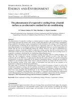
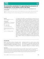
Fig. 1 Scanning electron microscopy (SEM, a-b, greyscale) and confocal images (c-d, false colour red) showing the 3D polymer scaffolds and
Arabidopsis thaliana cell growth in the scaffolds. a-b SEM images of 30 % PLA nanofibres, 70 % PET microfibre scaffold before cell seeding:
a front-view, b side-view. c-d 3-dimensional reconstructions of confocal z-stacks showing cells of Arabidopsis thaliana expressing a reporter
construct expressing cytoplasmic mCherry: c day 1 and d day 4 growth of cells inside the scaffold. Proliferation and growth were observed
throughout the scaffold. Cells increased in number and size from day 1 to day 4. Cells formed local points of attachment on the fibres (arrows)
and subsequently expanded in size into the porous space either by stretching from or winding around microfibres. For example, arrows 1 and 2
point to a cell attached to a microfibre at point 1 and growing into the depth of the fibrous scaffold as shown at point 2. Arrow 3 highlights a cell
wrapping around a microfibre. Scale bars: 100 μm
Luo et al. BMC Plant Biology (2015) 15:211
media and agitated at 130 rpm for 60 minutes (Additional
file 1: Figure S3). Furthermore, cells are observed to be in
contact with the microfibres (Fig. 1c, white arrows).
To determine whether the cell-fibre attachments are
active cellular interactions with the artificial structure or
simple passive entrapment of cells by the porous scaffold, we have repeated the cell culture experiment in the
scaffold using fluorescent silica particles of similar size
and concentration to the Arabidopsis cells in suspension.
The particles have a size range of 40–200 μm that resemble the size range of Arabidopsis cells. We observe
that the silica particles become passively trapped in the
scaffold, which acts as filters, but the particles readily
detach from the scaffold. By analysing scanning electron
microscope (SEM) images (Additional file 1: Figure S4)
and counting the number of silica beads on the scaffold
surface, we find approximately 94 % of the silica beads
filtered in the scaffold have detached from the scaffold
after agitation in the cell culture medium at 130 rpm.
The adherence of the cells to the fibres is not due to
excess mucilage released during cell culture from the
Page 4 of 15
seed-derived calli. Stable Arabidopsis cell culture lines
not derived from seed also grow in the scaffold and
interact with the fibres. Both seed-derived and non-seed
derived cells exhibit similar behaviour of winding and
twisting around microfibres as observed by light microscopy (Additional file 1: Figure S5), demonstrating that
cell-scaffold interactions are not due to seed mucilage.
Microfibres can be clearly imaged using confocal microscopy but nanofibres cannot be visualised. To understand cell-nanofibre interactions, a focused ion beam is
used to remove part of the cell surface during SEM,
showing a cell adapting its shape to enclose a nanofibre
(Fig. 2a-b). SEM experiments are done under both variable pressure (Fig. 3) and high vacuum modes (Fig. 2
and Fig. 4). Under variable pressure SEM mode, moist
samples are imaged at 40 Pa and cells deflated gradually
over several minutes. Cell-fibre attachments are observed and remain constant (Fig. 3). When the SEM
mode is changed from variable pressure to high vacuum
mode, cells deflate but remain attached to the scaffold.
Yellow arrows in Fig. 4b reveal the firm focal attachment
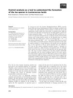
Fig. 2 a SEM image of a cross-section of a cell on top of a microfibre sliced by a focused ion beam, showing the attachment of the cell to a
nanofibre (red arrow). The surface of the cell, attached to the fibre, is shown by a red arrow. Internal cellular structures have been exposed after
ion beam milling. b-d SEM images under high vacuum conditions showing strong cell-fibre attachment to surrounding fibres, indicated by red
arrows. Scale bars: a 10 μm, b-d 50 μm
Luo et al. BMC Plant Biology (2015) 15:211
Page 5 of 15
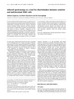
Fig. 3 Variable pressure SEM images obtained at 40 Pa, showing cell-fibre interactions in the scaffold. Local points of attachment between the cell
wall and the fibres are highlighted by red arrows. a An overview of cells in scaffold. b-d Images of single cell-fibre interactions.Scale bars: 100 μm
between the deflated cell and the neighbouring PLA
nanofibres. The cell remains wound around microfibres
(red arrows). In examples shown in Fig. 4c and d, where
cells do not wind around a fibre, but reach between two
fibres, the deflated single cell with no other support does
not detach from cell-fibre focal points (red arrows) and
remains immobilised like a bridge between two microfibres. Another example of a cell bridging gaps between
microfibres is shown in Fig. 1c.
The observations that (1) cells of diverse shape and
size are immobilised, and (2) cells maintain contact with
one or more fibres upon application of force, suggest a
physical interaction between the cells and the fibres is
more consistent with active adherence rather than passive entrapment. As evidenced by the adherence interactions above, the fibrous scaffold is able to provide a
three-dimensional support for plant cell culture growth
and morphogenesis. Plant cells respond to nanofibre
concentration in the scaffold in a similar fashion to that
observed in mammalian cell culture [7, 13], in which the
initial cell attachment density increases with increasing
nanofibre percentage in the scaffold. Specifically, cell
count increases from 5.4 ± 4.4 cells/mm2 for 0 % nanofibres, to 12.6 ± 3.6 cells/mm2 for 10 % nanofibres, to 93.5 ±
58.9 cells/mm2 for 30 % nanofibres (Fig. 5). All scaffolds
contain the same mass of PET with increasing mass of
PLA nanofibres. Compared to the PET microfibres, PLA
nanofibres can be described as a more voluminous and
tufted material. This led to an increase in the thickness of
the scaffold per unit area with an increasing PLA content,
but also resulting in an overall relatively unchanged porosity value (68 ± 1 %, see Methods) for all scaffolds despite
the changing nanofibre content. Hence, the increasing cell
seeding density with respect to nanofibre percentage in
the scaffold is not due to changes in porosity of the material that may change the space available for cell attachment
and growth. In addition, Arabidopsis cells appear to adhere with nanofibres at the cell surface, and continue to
conform and adapt their shape and orientation according
to the adjacent microfibres.
Cells interact with scaffolds and display shapes not
usually seen in planta
Large cells are found to grow adjacent to, between and
around microfibre supports, as well as across several
microfibres. Cultured and newly seeded cells commonly
exhibit shapes that are round, elongated-straight or
elongated-arced. Adhered cells can be seen to exhibit anisotropic expansion, growing between gaps within the
fibre. Where gaps are narrow, cells appear to alter their
shape to continue growth and the regions in narrow gaps
appear as constricted regions along the length of the cell.
For example, where parts of the cells seem severely restricted and “pinched” between two microfibres (Fig. 6a),
Luo et al. BMC Plant Biology (2015) 15:211
Page 6 of 15
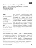
Fig. 4 SEM images obtained under high vacuum conditions showing cell-fibre interactions in a 3D microenvironment. Attachment points
between the cell wall and the micro- and nanofibres are highlighted by red and yellow arrows, respectively. a Overview of the abundant presence
of cells in the scaffold. Examples of cells are indicated by blue arrows. b-f Images of cells winding around or reaching between microfibres (red arrows)
with direct attachment to nanofibres (yellow arrows). As the cell deflated under vacuum, the cell wall pulled back with parts of the cell remaining
attached to the fibres. Scale bars: 100 μm
Luo et al. BMC Plant Biology (2015) 15:211
Page 7 of 15
Fig. 5 a-c SEM images at day 3 after seeding cells in scaffolds of varying nanofibre percentage. a No PLA nanofibres, 100 % PET microfibres. Few
cells grew on the scaffold, though a cell can be observed to interact with a PET microfibre (red arrow). b 10 % PLA nanofibres, 90 % PET microfibres.
c 30 % PLA nanofibres, 70 % PET microfibres. Compare the Scale bars: 500 μm
the rest of the cell appears to have expanded and explored
new space. Cells can also be found to occupy space along
the length of the same microfibre (Fig. 7e). 48–72 hours
after seeding, cells are seen to be very elongated, with numerous examples of spiral-shaped cells around microfibres (Fig. 6b, Fig. 8 and Additional file 1: Figure S6). As
Luo et al. BMC Plant Biology (2015) 15:211
Page 8 of 15
Fig. 6 Confocal images of actin-labelled Arabidopsis cells expressing the reporter construct 35S::GFP-FABD2, showing the actin patterns in growing
cells and the orientation of cells as they interact with the scaffold. a A pinched cell expanding. Microfibres exist in front of and behind the
constriction point (arrow) b Spiral shape of cell as it attached, interacted and wound around fibres inside the scaffold. Red arrows indicate points
of cell-fibre interactions. The large mass of actin corresponds to the nuclear basket. Scale bars: 100 μm
cells grew much larger they are seen to adopt more complex shapes (Fig. 7 a-d). Cells remain immobilised inside
the scaffold when we vary the vacuum condition from
variable pressure to high vacuum using a variable pressure
SEM. These extreme geometries and orientations of very
long and twisted cells are not present in the culture at the
time of seeding.
Cytoskeletal organisation in response to cell-fibre
interactions
Control of plant cell expansion requires the correct deposition of cell wall material, which is influenced by the
arrangement of the underlying cortical cytoskeleton formed
of microtubules and actin. In longitudinally (anisotropically) expanding cells, for example in hypocotyl or root
epidermal cells, actin appears as a complex network of
thick bundles or narrow fibres found in various orientations within a single cell and the actin network has been
shown to transport the Golgi apparatus and various types
of post-Golgi compartments that contain cell wall material
[14, 15]. Live observations of actin can be carried out
using confocal microscopy of a GFP fusion with a portion
of the Arabidopsis Fimbrin1 protein (called GFP-FABD2).
At sites of apparent space constriction, or where the cell
Fig. 7 Confocal z-projections showing cells adapting their shape to interact with the fibrous environment. a An overview. b-h Higher resolution
examples of cell shapes.White arrows indicate small round cells. Yellow arrows indicate cell-fibre interaction. Red asterisks in a-b indicate heterogeneous
growth between neighbouring cells, demonstrating the ability of the cells to slip past each other and continue elongation, a behaviour unobserved in
native tissues. GFP-labelled microtubules in cells expressing reporter construct 35S::GFP-MBD. Scale bars: 100 μm
Luo et al. BMC Plant Biology (2015) 15:211
Page 9 of 15
Fig. 8 Confocal z-projections showing GFP-labelled microtubule arrays in A. thaliana cells expressing reporter construct 35S::GFP-MBD. White arrows
indicate microtubules. Dotted lines trace fibres. a-c A cell spiraling twice around a microfibre. d-f Diagonal microtubules in spiral cells bending around
the central axis. g-h Conventional microtubule patterns perpendicular to direction of elongation. i Radial/criss-cross pattern of microtubules in small
round cells (diameter < 50 μm) and the tips of elongating cells. Scale bars: 100 μm
interacts with a fibre, actin can sometimes be observed to
bundle as shown in Fig. 6a, where intensely fluorescent
actin is observed close to the intersection of two microfibres (red arrow). Figure 6b shows actin in a cell undergoing spiral growth, where long actin filaments emanating
from the ends of the cells appear to converge on the nuclear basket. These observations may reflect local differences in transport of wall material to achieve a shape
change.
We next looked at microtubules in cells expressing a
fusion between GFP and the microtubule-binding domain of the mouse MAP4 protein. In cells exhibiting
anisotropic expansion, microtubules are observed to orient perpendicular to the long axis (Fig. 7f-h) – consistent with their role in directing cell reinforcement by
influencing cellulose deposition [16]. In ovoid (non
elongating) cells and in cells exhibiting complex shapes
(large cells in Fig. 7a-d), microtubules orientations are
not transverse to the long axis (red asterisk in Fig. 7a-b
and Additional file 2: Movie S1). An enlarged view of a
highly elongated portion of an irregular shaped cell is
shown in Additional file 1: Figure S7, in which microtubules are oriented predominantly along the long axis. In
the ovoid portions of the same cell, the microtubules
Luo et al. BMC Plant Biology (2015) 15:211
exhibit a mesh-like configuration. In cells growing in spirals around individual fibres (Fig. 8), microtubules are
often arranged diagonally, except for the ends of the cells
that, when viewed faced on, adopt the mesh-like configuration. Unlike natural tissues, in which cells cannot grow
past each other and often show homogeneous growth between neighbouring cells, the single cells in the scaffold
show heterogeneous growth between adjacent cells. Larger, elongating cells are capable of growing past fibres and
other obstructing cells to fill the available space (e.g. long
cell in Fig. 7a and b). As a proof-of-concept we could track
the growth and catastrophes of individual microtubules in
a 4D data series (Additional file 3: Movie S2). Further
work based on the 3D cell culture method reported in this
work will correlate microtubule orientations and cell wall
formation in Arabidopsis cells interacting with the 3D environment over time.
Applicability to other cell lines
The 3D scaffolds are applicable to studying cells of species besides Arabidopsis. We cultured mesophyll cells of
Zinnia elegans inside the scaffold. When cultured in
“non-inductive medium”, where cells do not differentiate
into tracheary elements, Zinnia cells continually exhibit
growth [17]. By imaging autofluorescence of the wet
cell-seeded scaffold, Zinnia elegans cells are observed to
grow along the fibres, and fewer cells are found in spaces
without the fibres (Additional file 1: Figure S8a-b). High
vacuum SEM (c, d) reveals regions of high density cell
seeding, together with apparent attachment points as previously found for the Arabidopsis cells. The high density
regions permit a closer look at cell-cell interactions that
are more akin to native tissue conditions, in which cells
are tightly packed. In a confined space delimited by fibres
(Fig. 9), three cells of similar size line up next to each
other and maintain contact along their long edges. This
Page 10 of 15
contrasts to what we have seen in Arabidopsis where
neighbouring cells grow past each other (Compare with
Fig. 7a).
Encapsulating plant growth substances within the
scaffold fibres
In mammalian 3D cell culture, hormones can be encapsulated in polymeric scaffolds for sequential and timed
release of implanted bioactive agents [18]. Auxin is a
principal regulator of growth and pattern formation in
plants. The synthetic auxin, 2,4-dichlorophenoxyacetic
acid (2,4-D), is readily soluble in organic solvents that
facilitates its incorporation during the formation of the
scaffolds. Briefly during scaffold fabrication, 0.5 % w/w
of 2,4-D is dissolved in a 15 % w/w PLA solution and
the mixture is shear-spun to form a fibrous PLA scaffold
(see Methods and ref [10]). Although the release profile
of auxin from the scaffold fibres is unknown, we find
5 % w/w 2,4-D or higher incorporation in the fibreforming solution results in rapid cell death, consistent
with its herbicidal properties. At 0.5 % w/w 2,4-D in the
polymer solution, cells on the resulting fibres can be
maintained for up to 3 days. As relatively small amounts
of auxin are already present to maintain plant cells in
culture, it is not immediately apparent if there is any
physiological response to the scaffold-released auxin.
The DR5::GFP construct has been used in BY2 cells, encoding a marker to visualise auxin uptake activity [19].
In our work, Arabidopsis DR5::GFP-ER yields a signal in
some cells within the liquid cultures, consistent with
DR5 response to the exogenous 2,4-D. We observe no
morphological responses of the cells to the extra auxin
released from the scaffold during the 3-day period of cell
culture, however, after 48 hours no GFP signal is observed
for cells seeded in the scaffold without the encapsulated
auxin, whereas the DR5 GFP signal is maintained within
Fig. 9 Average projection of images of Z. elegans cells taken 3 days after seeding in scaffolds. Shown are autofluorescence in the red spectrum
(left panel) and the corresponding transmission micrograph (right panel). Locations of fibres are marked as dashed lines. Alignment of cells in a
confined space is indicated by arrows. Scale bar: 100 μm
Luo et al. BMC Plant Biology (2015) 15:211
the auxin scaffolds (Additional file 1: Figure S9). Auxin efflux carriers, encoded by PIN genes, are known to be
polarly localised [20]. A polar distribution of PIN indicates
the presence and propagation of auxin gradients. PIN7GFP is observed in some liquid cultured cells as discrete
punctae representing intracellular vesicles, however, this
pattern of localisation remains unchanged in the auxin
scaffolds (Additional file 1: Figure S9), suggesting that either no microgradients exist or the isolated cells are unable
to detect or respond to these gradients. We found no detectable signal from a fusion between the principal efflux
protein PIN1 and GFP either in liquid culture or the cultures where 2,4-D is released from the scaffold, suggesting PIN1 is not expressed in these types of cultured cells.
Discussion
A number of technologies are shared in plant and animal biotechnology. Recent efforts with plant cells have
used lithographically defined structures to clarify the behaviour of pollen-tube growth and microfluidic systems
in general have allowed the control of local chemical
gradients and study of interactions with mechanical obstacles [1, 21–23]. Both lithography and microfluidic
systems are well known systems for mammalian cell
biology in healthcare applications such as diagnostics,
cancer research and regenerative medicine [3, 24–26].
Microfluidic systems provide cells with a confined and
well controlled environment akin to the in vivo plant tissue environment, but lack the structural sophistication
of a tissue environment. The 3D cell culture method
presented here is a complementary method useful for
studying morphological changes of isolated cells that
interact with an extracellular structure. Future work incorporating 3D scaffolds in a microfluidic device may
enable a better biomimetic environment.
Other methods and materials, such as 3D scaffolds in
tissue engineering and regenerative medicine of animal
cells have potential applications in plant sciences. We
have demonstrated that 3D nano- microfibre scaffolds
can be applied as an effective tool for studying plant cell
morphogenesis and can help identify new capabilities of
growth at the cellular level. The scaffold materials, PLA
and PET, are both hydrophobic and require pre-wetting
of the fibre scaffold in culture media prior to use. Despite the hydrophobicity, cells are completely immobilised
within the scaffold, and focal points (suggesting cellfibre attachment) are observed with the SEM. Further
studies will investigate if the attachment is through adhesion, by investigating known components such as the
type and distribution of pectin. If attachment is found to
be through adhesion, it would suggest cells of land
plants have retained the ability to adhere to relatively
inert supports, much like single-celled organisms from
their ancestral lineage, represented by the green algae of
Page 11 of 15
the charophyta [27, 28]. A recent report has found similarities in composition and structure between the adhesive matrix of Penium, a charophytic green alga, and the
middle lamella of land plants that permits the integration of cells into complex tissues [27]. One biological
focus of future work is to determine whether the interface between cell-fibre contacts is similar to those of
cell-cell contacts.
Shapes of cells in scaffolds range from regular ovoid or
cuboid to complex shapes with constrictions where local
space appears limited, some even have projections resembling, to some degree, the lobes of leaf pavement
cells (Fig. 7d upper right portion of the cell). Coupled
with these complex shapes, growth resulted in large sizes
of some cells (500 μm in axial length). This may be due,
in part, to having a tissue-like environment without the
constraints of tightly packed or attached cells and we envisage that the scaffolds will help us determine the factors that govern the upper size limit of a plant cell, a
subject of recent discussion [29].
Long cells often grow and orient along the microfibres
in either a left-handed or a right-handed spiral conformation. We assume that spiral growth is akin to growing
along a flat surface but, given that the diameter of the
cell (>40 μm) is many times that of a microfibre (10 μm),
the cells grow around the support. To maintain such
spiral growth, the cell would likely adhere to the microfibre. It seems likely that the stiffness of the microfibre
also contributes to cell growth, and this may be why we
do not see spiral morphologies associated with nanofibres.
The interaction and adhesion between cells and the
microfibres are most likely due to cell wall-fibre interactions. The cell wall defines plant cell shape, which is
dependent on the balance between turgor pressure and
the structure and composition of the cell wall that is in a
constant flow of synthesis and remodelling, based on the
type and developmental stage of the cell [30]. For a cell to
change its shape, the cell wall must first undergo controlled and sometimes local loosening [31]. A number of
experimental studies indicate that a sensing and signalling
system exists in the plant that monitors the structure and
integrity of cell walls [30]. The new method of 3D plant
cell culture reported here has potential to explore the relationships between signalling, synthesis and remodelling of
the wall through genetic strategies such as use of existing
collections of Arabidopsis insertion (mutant) lines and
more reporter constructs. Future work will make use of
other materials that are bio-inert or bioactive, including
cellulosic fibres, to further study the cellular sensing and
responses to external materials that resemble the cell wall.
It is noteworthy to compare the cellular responses described here with those of a study looking at improving
the production of secondary metabolites by Lindsey and
coworkers [32]. The latter study took carrot and pepper
Luo et al. BMC Plant Biology (2015) 15:211
suspension cultures, immobilised in polyurethane foam,
and concluded that the immobilised cells have a metabolism that is closer to the respective whole plant – a
useful property for industrial applications. Similar to our
3D culture, the polyurethane foam provides pores that
are occupied by the cells, however, the polyurethane
foam pores require a high seeding density for cells to be
immobilised whereas the fibre scaffolds can immobilise
single isolated cells. The foam-immobilised cells are also
firmly attached since agitation does not dislodge them –
an identical result to our 3D scaffolds. For carrot cells,
the foam-immobilised cells can grow to a large size (up
to 100 μm) and show a variety of shapes. Although these
shapes do not achieve the complexity observed for our
fibre scaffolds, the tight packing of the diverse carrot
cells within the pores does resemble a simple intact tissue. Tight packing is observed in confined region of
scaffold containing Z. elegans cells where cell growth
and shape appeared largely homogenous. Arabidopsis
cells are seen to grow past each other and no close packing or homogeneous growth of cells are observed for
these cultures. The differences we observe between Z.
elegans and Arabidopsis in scaffolds may be a function
of (1) the higher seeding densities achieved with Z. elegans, which is 100x higher than Arabidopsis; and (2) the
tissue the cells are derived from (Z. elegans cells are the
mesophyll cells of leaves, whereas the Arabidopsis cells
are from seed-derived calli).
The cytoskeleton, in particular the microtubules, are
believed to play important roles in guiding the morphological changes of cells in response to the surrounding
scaffold. Drugs that affect cytoskeleton function, such as
oryzalin, latrunculin B and nocodazole, can be used in
future investigations to better understand cell growth
and morphological changes in scaffold-embedded culture media. Future work will also explore the possibility
of targeting delivery of growth effectors such as hormones and cytoskeletal inhibitors by incorporating them
directly into the scaffold. As a proof-of-concept, we have
encapsulated the synthetic auxin, 2,4-D, within fibres.
The next challenge is to better manage its release from
the scaffold. This would potentially give rise to similar
microgradients as found in the whole organism.
In summary, nano-structured scaffolds provide a powerful mechanism to encourage and direct cell behaviour ranging from cell adhesion to gene expression in animal
tissue culture [3, 6, 33]. We envisage similar responses for
plant cells leading to existing imaging, biochemical and
genetic techniques being applied in fibris.
Conclusions
We have developed a simple system that permits the study
and facilitates imaging of fluorescently labelled cells interacting with a 3D environment. We have demonstrated
Page 12 of 15
that physical interactions with the local environment result in complex growth and morphogenesis.
Methods
Plant material
Arabidopsis thaliana lines expressing reporter constructs
35S::GFP-MBD are used for visualising cortical microtubules, and 35S::GFP-FABD2 for visualising actin (gift from
Tijs Ketelaar, Wageningen). Cytoplasmic mCherry is observed using a 35S::mCherry-TUA5 line that does not label
microtubules (gift from Arun Sampathkumar, California
Institute of Technology [34]). Lines containing DR5::GFPER and PIN7-GFP have been described previously [35, 36].
Seeds are surface sterilised for 15 minutes in sterilising solution consisting of 15 % Sodium Hypochlorite and 1 %
Triton X-100 and washed 4 times in sterile water and finally resuspended in 4 volumes of sterile water. Seeds are
vernalised at 4 °C for at least 48 hours before use in suspension culture.
The maintained cultured cells of Arabidopsis thaliana
ecotype Colombia-0, used as a non-mucilage control, are
a gift from Matthew Smoker (Sainsbury Laboratory,
Norwich). Cells are maintained in MS liquid media containing Gamborg B5 vitamins and supplemented with
sucrose (30 g l−1), 2-(n-morpholino)-ethanesulfonic acid
(0.59 g l−1), 2,4-dichlorophenoxyacetic acid (1 mg l−1).
Zinnia elegans cells are propagated from mesophyll
cells in non-inductive culture medium as described in
Twumasi et al. [17]. Cells are dispensed in tubes containing pre-wetted scaffold at an initial density of 2 ×
106 cells ml−1.
Arabidopsis cell culture preparation
Cell suspension cultures are prepared from Arabidopsis
seed calli based on the protocol from Kevei et al. [37].
The culture medium consists of MS powder (Sigma
M5524 4.32 g l−1), sucrose (30 g l−1), 2,4-dichlorophenoxyacetic acid (125 μg l−1), kinetin (15 μg l−1) and B5
vitamin stock (2 ml l−1 of stock consisting of 0.1 % w/v
nicotinic acid, 0.1 % pyridoxine-HCl, 1 % thiamine-HCl
and 10 % myo-inositol). Approximately 200 μl of surface
sterilised and vernalised seeds are added to 40 ml culture
media in a 500 ml flask followed by agitation at 130 rpm.
Cultures are incubated at 22 °C until a suspension density
of between 2 – 6 × 10⁴ cells ml−1 (7–21 days).
Seeding cells to fibrous scaffolds
All procedures take place aseptically in a laminar airflow cabinet. The scaffolds are pre-wetted in fresh culture medium and stirred with a sterile rod to remove
trapped air. Scaffolds are placed in a Nunc® cryotube
(Thermo Scientific cat no. 368632) towards the bottom
placed at an oblique angle so that liquid can pass freely
over and through the scaffolds during agitation. 1.5 ml
Luo et al. BMC Plant Biology (2015) 15:211
Page 13 of 15
of cell culture together with 0.5 ml of fresh MS medium
is dispensed in a 2 ml CryoTube™. The scaffolds contain
predominantly single cells than clumped cells and the
quantity of cells within the scaffold varied between
Arabidopsis lines and between experiments. The tubes
are left to stand for 30 minutes, followed by placing
them horizontally under agitation at 130 rpm. Cells are
seeded in multiple scaffolds and at intervals, up until
11 days, one scaffold is removed for microscopy. To
maintain the cells in scaffolds beyond 4 days, the culture
medium needs to be replaced daily. Without this media
change, lysed cells are observed by day 6, due to depletion of nutrients in the medium. The majority of the images were taken using scaffold-incubated cells taken
between days 2 and 4 for a 2 ml culture without changing the MS medium.
electron microscope (FEI Helios) is used to image and
cut the samples. For the FEI SEMs, each SEM sample is
coated with gold using a sputtering machine (Emitech
K550, Emitech Ltd, UK) for 120 s prior to observation.
The coating is approximately 15 nm in thickness. For
the Zeiss EVO HD, samples are placed directly on the
stage without processing. Gun emission is set to 10–
20 kV. All images are acquired using the backscatter detector. Variable Pressure (VP) imaging is carried out at
40 Pa. Due to the apparently delicate nature of the cells
from the long-term line (non-mucilage control), highly
deflated cells are observed under VP mode.
Films are sometimes observed in the SEM images,
(e.g. the top corner of Fig. 3b). These films are attributed
to the MS culture medium, as the same films are also
seen in scaffolds agitated in MS medium without cells.
Live imaging of cells within scaffolds
Image processing
For microscopic observations, the fibre scaffolds are either transferred to glass slides, maintained wet and observed with standard non-immersion objectives (without
the addition of a cover slip); or for imaging at longer
working distances, they are submersed in fresh growth
medium, followed by imaging using a water-dipping objective. High-resolution 3D imaging and time lapse 4D
imaging typically involve timescales between 5 and
45 minutes, during which multiple frames are averaged
using the frame averaging feature in the imaging software to improve the signal to background noise ratio.
Live imaging is carried out using a Zeiss LSM700 confocal microscope, a Zeiss LSM780 confocal microscope
or a Zeiss Axioimager M2 optical microscope fitted with
DIC optics. For immediate imaging with the 20x NA 0.8
plan-apochromat non-immersion objective, scaffolds are
removed from tubes and placed flat on a glass slide. To
achieve longer working distances at higher resolution,
scaffolds are placed in a small container or petri dish
and weighed down at the edges using steel razor blades
and covered with growth media. A 20x NA 1.0 waterdipping objective is then carefully lowered into the liquid. Multi-dimensional acquisition is carried out using
Zen software where a z-spacing of between 0.4 – 1 μm
is used for acquiring stacks. Both GFP and fibre fluorescence are acquired simultaneously using 488 nm excitation and emission collected at between 495 and 555 nm
(GFP) and between 560 and 735 nm (for fibre autofluorescence). mCherry, together with fibre autofluorescence
are visualised using 555 nm excitation and emission collected between 560 and 735 nm.
The micrographs are analysed using ImageJ, a public domain Java image-processing program. The tonal range and
colour balance of the images are optimised to sharpen the
contrast of the fibres and cells against the background,
using the levels histogram in photoshop to adjust intensity
levels of shadows, midtones, and highlights.
Scanning electron microscopy
Scanning electron microscopes (models: FEI Nova
NanoSEM™, Zeiss EVO HD15) are used to analyse the
dried samples. In addition, a focused ion beam (FIB)
3D fibre scaffolds
Shear-spun fibrous scaffolds as dry thick discs (>50 μm
thick) of interlocking homogeneously entangled microfibres with nanofibres (Xanofi Ltd., North Carolina, USA)
are used. The scaffolds consist of PLA nanofibres and
PET microfibres. Little is known about scaffold biocompatibility requirements for plant cells and how the cells
interact with a scaffold. PLA–PET scaffolds are used as
they are commercialised 3D scaffolds made by shear
spinning, which is under investigation for tissue engineering in our laboratory.
The ability to achieve uniform nanofibre dispersion
and control of porosity in a bulk scaffold is a unique feature of the shear spinning method. Other nanofibreforming techniques, including electrospinning, can only
achieve dense and thin sheets with nanometre-pores and
micrometre-thickness, leaving cells unable to move
through the pores; shear-spun scaffolds can provide various nanofibre percentages while maintaining the same
porosity profile.
Three different scaffolds with varying percentages by
weight of nanofibre to microfibre ratios but similar porosity profiles are tested to observe the influence of nanofibres percentage on cell seeding efficiency and growth
profile. The scaffold types are 100 % PET microfibres;
10 % PLA nanofibres, 90 % PET microfibres; and 30 %
PLA nanofibres, 70 % PET microfibres. The scaffold material is cut to 10 mm × 10 mm pieces prior to sterilisation treatment and cell seeding.
Luo et al. BMC Plant Biology (2015) 15:211
The porosity of the scaffold of each percentage ratio of
nano- and microfibres are characterised. Specifically, the
mass of a dry scaffold, m, is measured using a digital balance. The width, w, and length, L, of the scaffold are
measured using a digital caliper. The thickness of the
scaffold (h) is imaged by SEM. Three measurements are
taken per sample and the average values recorded. The
porosity is calculated using the following equation:
Porosity (%) = [(1 − ad)/bd] × 100. Where, ad is the polymer(s) apparent density (gcm−3), calculated as ad = m/
(h × w × L); bd is the bulk density of pure amorphous
polymer(s) prior to fibre formation. The amorphous
densities of the polymers are provided by the supplier
Xanofi Ltd, respectively 1.24 g cm−3 and 1.38 g cm−3 for
PLA and PET polymers. The average cell count per
mm2 is calculated based on 3 samples per type of scaffold, over an area of 2 mm2 per sample.
Encapsulation of auxin
Synthetic auxin, 2,4-dichlorophenoxyacetic acid (2,4-D,
C8H6Cl2O3) is dissolved (0.5 % w/w) in 15 % w/w PLA
in chloroform/methanol 3:1 v/v solution. The resultant
mixture is shear-spun into microfibrous scaffolds and
X-ray sterilised for cell culture. Shear spinning process
has been previously described [10]. Control studies are
carried out in parallel, using (1) cell suspension with
no scaffold, (2) cells in scaffolds made by the same
method but without auxin.
Optimising sterilisation methods for the scaffolds
Ethanol treatment
The scaffold is immersed in 100 % ethanol for 2 hours
and stored in a sealed Petri dish. The ethanol-treated scaffold is immersed in cell culture medium for 10 minutes in
laminar air-flow cabinet prior to cell seeding. Some residue ethanol in the scaffold is possible.
Page 14 of 15
Additional files
Additional file 1: Figures S1-S9. Figure S1. Projections of confocal
z-stacks of Arabidopsis thaliana cells containing the microtubule
reporter construct 35S::GFP-MBD: (a-b) immediately before seeding into
scaffolds; (b-e) at day 2, 6 and 11 of scaffold incubation. Scale bars:
100 µm. Figure S2. Scaffold morphology observed under SEM (a)
before treatment, (b) after UV treatment, (c) after 18 min X-Ray
treatment, (d) after immersion in ethanol for 2 hr. Extensive nanofibre
fusion is observed in (d). Scale bars: 400 µm. Figure S3. SEM image of a
seeded scaffold incubated in growth medium under constant agitation.
Arrows indicate small, round and immobilised cells of 47 ± 8 µm.
Scale bar: 500 µm. Figure S4. Silica beads (diameter range 40–200 µm,
2.5 x 10⁴ beads per ml-1 in MS growth medium) trapped in the scaffold
(a) before and (b) after constant agitation at 130 RPM for 3 days. Scale
bars: 100 µm. Figure S5. DIC microscopy of a cell culture free from
seed-mucilage contamination. Images show a cell wrapping around a
microfibre and interacting with neighbouring fibres. Depth of view:
(a) 0 µm, (b) 7.2 µm. Arrows indicate cell-fibre interaction. Red lines
highlight relevant microfibres. Scale bars: 100 µm. Figure S6. Spiral
growth of a cell around a microfibre. Red lines highlight locations of
microfibers. (a) Actin reporter (b) transmission. Scale bars: 100 µm.
Figure S7. Confocal z-projections showing GFP-labelled microtubule
patterns in A. thaliana cells expressing the reporter construct 35S::GFP-MBD.
White arrows indicate microtubules aligned parallel with the principal
growth direction. Main panel scale bar: 100 µm. Figure S8. Confocal (a-b,
showing autofluorescent cells and microfibres) and high vacuum SEM (c-d,
greyscale) images of mesophyll cells of Zinnia elegans cultured in scaffolds
at day 3 after seeding. Arrows indicate cell-fibre interactions. Scale bars:
100 µm. Figure S9. Arabidopsis cells expressing DR5::GFP-ER in unmodified
scaffolds (a GFP, b transmission, cell outlines are indicated by arrowheads)
and in scaffolds encapsulated with the synthetic auxin 2,4-D (c). Scale bars:
100 µm (d) Cell-scaffold PIN7-GFP is observed in discrete punctae (arrows)
and the localisation does not differ from cells in liquid culture (data not
shown). Scale bar: 10 µm.
Additional file 2: An Apple Quicktime movie named Movie S1.mov
820 showing a 3D reconstruction of confocal z-stack of microtubule
821 organisation in a rounded cell existing and interacting between
two 822 individual fibres. (MOV 5686 kb)
Additional file 3: A Windows Media movie Movie S2.avi showing a
824 4D dataset of microtubule dynamics. White arrow shows the plus
end 825 of an individual microtubule undergoing rounds of growth
(polymerisation) 826 and catastrophe (depolymerisation). (AVI 699 kb)
Competing interest
C.J.L., R.W., E.M.M. declare no competing interest. S.S. serves on Xanofi’s board of
directors and declares financial interest in the scaffolds used in this work.
Ultraviolet irradiation
The scaffolds are placed in a Petri dish of 12 mm diameter. The polystyrene Petri dish is sealed with Parafilm®
and placed on aluminium foil. Irradiation is carried out
with a ultraviolet lamp (8 W, 3UV™-38, UVP, Cambridge,
UK) at a wavelength of 254 nm and a distance of
50 mm. Samples are irradiated for a total time of two
hours, and are turned over halfway through the treatment to irradiate the top and bottom surfaces.
X-ray irradiation
Dry scaffolds are placed in CryoTube™ vials (Thermo
Scientific, UK), and placed in the centre of the X-Ray
chamber (0.5 mm Cu filter, 220 kV, 14 mA, Pantak
PMC1000). Each scaffold is irradiated at a dose of
417 cGy/min for 18 minutes.
Authors' contributions
Concept, CJL, RW; methodology, CJL, RW; acquisition of data, CJL, RW;
analysis and interpretation, CJL, RW, SS, EM; drafting and editing of the
manuscript, CJL, RW, SS, EM. All authors read and approved the manuscript.
Acknowledgements
This work is funded by the Gatsby Charitable Trust through Fellowships
GAT3272/C and GAT3273-PR1 to E.M.M. and the European Research Council
grant EMATTER 280078 to S.S.
Author details
1
Department of Materials Science and Metallurgy, University of Cambridge,
27 Charles Babbage Road, Cambridge CB3 0FS, UK. 2Sainsbury Laboratory,
University of Cambridge, Bateman Street, Cambridge CB2 1LR, UK. 3Division
of Biology and Biological Engineering, and Howard Hughes Medical Institute,
California Institute of Technology, Pasadena, CA 91125, USA.
Received: 25 June 2015 Accepted: 24 July 2015
Luo et al. BMC Plant Biology (2015) 15:211
References
1. Sanati Nezhad A. Microfluidic platforms for plant cells studies. Lab Chip.
2014;14:3262–74.
2. Choi NW, Cabodi M, Held B, Gleghorn JP, Bonassar LJ, Stroock AD.
Microfluidic scaffolds for tissue engineering. Nat Mater. 2007;6:908–15.
3. Carletti E, Motta A, Migliaresi C. Scaffolds for Tissue Engineering and 3D Cell
Culture. In 3D Cell Culture. Methods in Molecular Biology. Edited by
Haycock JW. New York City, United States: Humana Press; 2011;695:17–39.
4. Fischbach C, Chen R, Matsumoto T, Schmelzle T, Brugge JS, Polverini PJ,
et al. Engineering tumors with 3D scaffolds. Nat Methods. 2007;4:855–60.
5. Griffith LG, Swartz MA. Capturing complex 3D tissue physiology in vitro. Nat
Rev Mol Cell Biol. 2006;7:211–24.
6. Pham QP, Sharma U, Mikos AG. Electrospinning of polymeric nanofibers for
tissue engineering applications: A review. Tissue Eng. 2006;12:1197–211.
7. Kim YB, Kim G. Rapid-prototyped collagen scaffolds reinforced with PCL/βTCP nanofibres to obtain high cell seeding efficiency and enhanced
mechanical properties for bone tissue regeneration. J Mater Chem.
2012;22:16880–9.
8. Zhong S, Zhang Y, Lim CT. Fabrication of Large Pores in Electrospun
Nanofibrous Scaffolds for Cellular Infiltration: A Review. Tissue Eng Part B
Rev. 2012;18:77–87.
9. Velev OD, Smoukov S, Marquez M: Nanospinning of Polymer Fibers from
Sheared Solutions. United States Patent 8551378; 2013.
10. Smoukov SK, Tian T, Vitchuli N, Gangwal S, Geisen P, Wright M, et al.
Scalable Liquid Shear-Driven Fabrication of Polymer Nanofibers. Adv Mater.
2015;27(16):2642-7.
11. Velev OD, Alargova RG: Process for Preparing Microrods Using Liquid-Liquid
Dispersion. United States Patent 7323540; 2008.
12. Shearer H, Ellis MJ, Perera SP, Chaudhuri JB. Effects of Common Sterilization
Methods on the Structure and Properties of Poly(D, L Lactic-Co-Glycolic
Acid) Scaffolds. Tissue Eng. 2006;12:2717–27.
13. Kwon IK, Kidoaki S, Matsuda T. Electrospun nano- to microfiber fabrics made
of biodegradable copolyesters: structural characteristics, mechanical
properties and cell adhesion potential. Biomaterials. 2005;26:3929–39.
14. Seagull RW, Falconer MM, Weerdenburg CA. Microfilaments: dynamic arrays
in higher plant cells. J Cell Biol. 1987;104:995–1004.
15. Akkerman M, Overdijk EJR, Schel JHN, Emons AMC, Ketelaar T. Golgi body
motility in the plant cell cortex correlates with actin cytoskeleton
organization. Plant Cell Physiol. 2011;52:1844–55.
16. Paredez AR, Somerville CR, Ehrhardt DW. Visualization of Cellulose Synthase
Demonstrates Functional Association with Microtubules. Science.
2006;312:1491–5.
17. Twumasi P, Schel JHN, van Ieperen W, Woltering E, Van Kooten O, Emons
AMC. Establishing in vitro Zinnia elegans cell suspension culture with high
tracheary element differentiation. Cell Biol Int. 2009;33:524–33.
18. Enayati M, Ahmad Z, Stride E, Edirisinghe M. One-step electrohydrodynamic
production of drug-loaded micro- and nanoparticles. J R Soc Interface.
2010;7:667–75.
19. Barbez E, Laňková M, Pařezová M, Maizel A, Zažímalová E, Petrášek J, et al.
Single-cell-based system to monitor carrier driven cellular auxin
homeostasis. BMC Plant Biol. 2013;13:20.
20. Křeček P, Skůpa P, Libus J, Naramoto S, Tejos R, Friml J, et al. The PINFORMED (PIN) protein family of auxin transporters. Genome Biol.
2009;10:249.
21. Sanati Nezhad A, Naghavi M, Packirisamy M, Bhat R, Geitmann A.
Quantification of the Young’s modulus of the primary plant cell wall using
Bending-Lab-On-Chip (BLOC). Lab Chip. 2013;13:2599–608.
22. Sanati Nezhad A, Packirisamy M, Bhat R, Geitmann A. In vitro study of
oscillatory growth dynamics of Camellia pollen tubes in microfluidic
environment. IEEE Trans Biomed Eng. 2013;60:3185–93.
23. Sanati Nezhad A, Ghanbari M, Agudelo CG, Naghavi M, Packirisamy M,
Bhat RB, et al. Optimization of flow assisted entrapment of pollen grains in
a microfluidic platform for tip growth analysis. Biomed Microdevices.
2014;16:23–33.
24. Abate AR, Kutsovsky M, Seiffert S, Windbergs M, Pinto LFV, Rotem A, et al.
Synthesis of Monodisperse Microparticles from Non-Newtonian Polymer
Solutions with Microfluidic Devices. Adv Mater. 2011;23:1757–60.
25. Barrero A, Loscertales IG. Micro- and nanoparticles via capillary flows. Annu
Rev Fluid Mech. 2007;39:89–106.
26. Chatterjee K, Sarkar S, Jagajjanani Rao K, Paria S. Core/shell nanoparticles in
biomedical applications. Adv Colloid Interface Sci. 2014;209:8–39.
Page 15 of 15
27. Domozych DS, Elliott L, Kiemle SN, Gretz MR. Pleurotaenium trabecula, a
desmid of wetland biofilms: the extracellular matrix and adhesion
mechanisms1. J Phycol. 2007;43:1022–38.
28. Domozych DS, Sørensen I, Popper ZA, Ochs J, Andreas A, Fangel JU, et al.
Pectin Metabolism and Assembly in the Cell Wall of the Charophyte Green
Alga Penium margaritaceum1[W][OPEN]. Plant Physiol. 2014;165:105–18.
29. Marshall WF, Young KD, Swaffer M, Wood E, Nurse P, Kimura A, et al. What
determines cell size? BMC Biol. 2012;10:101.
30. Ringli C. Monitoring the Outside: Cell Wall-Sensing Mechanisms1[C]. Plant
Physiol. 2010;153:1445–52.
31. Cosgrove DJ. Growth of the plant cell wall. Nat Rev Mol Cell Biol.
2005;6:850–61.
32. Lindsey K, Yeoman MM, Black GM, Mavituna F. A novel method for the
immobilisation and culture of plant cells. FEBS Lett. 1983;155:143–9.
33. Stevens MM, George JH. Exploring and Engineering the Cell Surface
Interface. Science. 2005;310:1135–8.
34. Gutierrez R, Lindeboom JJ, Paredez AR, Emons AMC, Ehrhardt DW.
Arabidopsis cortical microtubules position cellulose synthase delivery to the
plasma membrane and interact with cellulose synthase trafficking
compartments. Nat Cell Biol. 2009;11:797–806.
35. Friml J, Vieten A, Sauer M, Weijers D, Schwarz H, Hamann T, et al. Effluxdependent auxin gradients establish the apical–basal axis of Arabidopsis.
Nature. 2003;426:147–53.
36. Blilou I, Xu J, Wildwater M, Willemsen V, Paponov I, Friml J, et al. The PIN
auxin efflux facilitator network controls growth and patterning in
Arabidopsis roots. Nature. 2005;433:39–44.
37. Kevei Z, Baloban M, Da Ines O, Tiricz H, Kroll A, Regulski K, et al. Conserved
CDC20 Cell Cycle Functions Are Carried out by Two of the Five Isoforms in
Arabidopsis thaliana. PLoS ONE. 2011;6:e20618.
Submit your next manuscript to BioMed Central
and take full advantage of:
• Convenient online submission
• Thorough peer review
• No space constraints or color figure charges
• Immediate publication on acceptance
• Inclusion in PubMed, CAS, Scopus and Google Scholar
• Research which is freely available for redistribution
Submit your manuscript at
www.biomedcentral.com/submit