Preprocessing a static finite elements simulation for a transtibial prosthesis using cae tools
Bạn đang xem bản rút gọn của tài liệu. Xem và tải ngay bản đầy đủ của tài liệu tại đây (585.27 KB, 12 trang )
International Journal of Mechanical Engineering and Technology (IJMET)
Volume 10, Issue 12, December 2019, pp. 311-322, Article ID: IJMET_10_12_034
Available online at />ISSN Print: 0976-6340 and ISSN Online: 0976-6359
© IAEME Publication
PREPROCESSING A STATIC FINITE
ELEMENTS SIMULATION FOR A
TRANSTIBIAL PROSTHESIS USING CAE
TOOLS
Juan Sebastián Lasprilla, Hoffman F. Ramírez, Mauricio Mauledoux
DAVINCI Research Group, Mechatronics Engineering Department,
Military Nueva Granada University, Bogota, Colombia
ABSTRACT
People with physical-motor disabilities who make use of prosthetic devices, have
the need for these prostheses to be designed to fulfill the tasks of their daily lives,
regardless of the level of physical activity they maintain. This particular problem can
be approached from the mechanical design of the prostheses, having as a critical
stage, the validation of the components designed for its operation. Therefore, to
improve the designs, a stage of determining the forces that the device must withstand
is necessary. For this reason, a stage where all the forces affecting the prosthesis are
determined is necessary. For this work, simulations can be used in specialized
programs and finite element analysis methods to detail the behavior of virtual models
under specific conditions critical to the design. This document focuses on the
approach of a computerized motion analysis to structure the preprocessing of a static
finite element simulation, used in the design of a transtibial prosthesis for a
Paralympic cyclist, and thus evidence the behavior of the proposed prosthesis model
under the charges present during competition.
Keywords: Mechanical design, finite element analysis, CAD modeling, transtibial
prosthesis, motion analysis
Cite this Article: Juan Sebastián Lasprilla, Hoffman F. Ramírez, Mauricio
Mauledoux, Preprocessing a Static Finite Elements Simulation for a Transtibial
Prosthesis Using CAE Tools. International Journal of Mechanical Engineering and
Technology 10(12), 2019, pp. 311-322.
/>
1. INTRODUCTION
When talking about prostheses for Paralympic athletes, it should be considered that physical
activity levels are much more exhausting and intense than those of a normal person.
Therefore, to correctly design a transtibial type prosthesis for an Olympic athlete in a
condition of disability it is necessary to carry out studies and analyses that validate these
designs, with the aim not only of positively impacting the athlete's physical performance but
also in minimizing physiological impacts of the use of prostheses.
/>
311
Juan Sebastián Lasprilla, Hoffman F. Ramírez, Mauricio Mauledoux
In this way, the first measure to consider in the process of design, analysis, and validation
of a transtibial prosthesis, is the determination of the loads to which the socket is exposed
since this is the part that absorbs and redirects the energy applied to the overall assembly of
the prosthesis. For this work, it is necessary to consider the complexity of the form and the
way in which the weight and force exerted by the person are distributed between the stump
and the socket.
Initially, it is necessary to categorize the type of socket necessary for the desired
application since there are currently different ways of attaching the socket to the stump. In the
study [1], they show detailed uses of the different types of prosthetic sockets with the
representative restrictions for certain types of activities. Thus, by validating the objective of
the final function of the prosthetic device, it is possible to slightly delimit the analysis process
of the forces exerted on the socket. Similarly, in the study [2], it is detailed, according to the
stump profile, how the forces applied on the socket should be distributed.
However, these studies are based on a uniform distribution from the socket „s reaction
forces, an event that shows no correlation with reality. An experimental method is necessary
to determine the reaction forces that are generated on the system through instrumented
sockets, which allow to experimentally measure the pressures generated between the stump
and the socket when external forces are applied to the system. An example of this is sockets
instrumented with pressure measurement systems, such as the one used in the study [3]. This
socket (figure 1), is made up of 4 lines of transducer arrays, forming more than 350 measuring
points in the system, which allows having a percentage of more than 90% of stump coverage.
Figure 1. Instrumented socket with transducer array.
This process carries expenses in terms of time and money, not only because of the
repetitiveness involved in the construction of test sockets to implement them, but also, for the
acquisition of sensors with the ease for being adapted to the irregular shape of the socket
model and the capability of withstanding pressure measurement levels.
To improve and optimize these physical prototype design and validation processes, a
computational simulation can be used, such as motion analysis, which facilitates the stress
distribution determination presented in a model, and thus subsequently be able to perform
different independent analyzes of each element of the model [4] [5] [6]. This process is
detailed in the study titled [7], where they show the process of designing and simulating a
socket for a transtibial amputation. In this design, the maximum pressure points are
determined using FEA (finite element analysis) with the objective of using compliant
mechanical designs to minimize the mentioned pressure points.
This type of simulation is also useful when material studies are required, since by using
the simulation environments, it is possible to apply specific material properties and, therefore,
determine, according to established methodologies and simulation parameters, behaviors from
/>
312
Preprocessing a Static Finite Elements Simulation for a Transtibial Prosthesis Using CAE Tools
different types of materials for a specific design. These types of simulations can be seen in the
study [8], where they are based on four simulation elements: carbon fiber, polypropylene,
HDPE (High Density Polyethylene) and LDPE (Low Density Polyethylene). This process is
carried out in order to determine which material has the best behavior in terms of the types of
force and boundary conditions used for the definition of the simulation model.
As a last resort to consider in the process of a transtibial prosthesis correct design and
analysis, it is the mechanical model and free-body diagrams of the system. This part
determines the principles of mechanical movement for the prosthetic device, taking into
account variables such as the weights of the components, forces, torques, movement angles,
among others so that it is possible to determine equations that characterize the movement and
can be used to determine the boundary conditions or critical times in which the system must
be exposed to maximum forces, pressures or torques that affect the integrity of the design
itself. In the study [9], they propose a free-body diagram for a transtibial prosthesis,
considering mainly the weights of the orthopedic components, the forces, and torques
generated by the characteristic movements of a lower limb (leg), to determine the equivalent
forces, and the torques generated on the prosthesis joints [9]. Likewise, different studies
propose an analysis of free body diagrams to determine the specific behavior that describes
the mechanical contact between the socket and the stump, making use of different
mathematical approaches with optimization methods to minimize and delimit the scope of the
variables used in the models proposed [10] [11].
In conclusion, the purpose of carrying out the necessary studies that validate the design
process and analysis of the prosthetic device under certain conditions is to validate and give
scientific support to the proposed design, so that it is accepted by the community and can be
viable for future implementations.
2. DESCRIPTION OF THE PROSTHESIS
Initially, to guarantee a proper design, it is necessary to establish a control process on some of
the anthropometric and biomechanical parameters that are most important for the design
objective (Table 1).
Table 1. Anthropometric and biomechanical design parameters.
PARAMETER
MEASURE
Age
Height
Weight
Activity level
Stump length
(Long transtibial amputation)
Length not affected Leg
25-30
1.70-1.80
65-75
K3*
0.14
years
m
kg
m
0.50
m
Based on the proposed anthropometric characteristics and the considerations for low-cost
and modularity design, an assemble that not only complied with these parameters but was also
designed under modularity components and high mechanical strength was proposed.
This design is composed of eight main pieces, which have the possibility of being
modifiable in terms of prosthesis height, characteristic angles of the ankle joint and the
implemented foot model.
The general design consists of three major sections (Figure 2). This is mainly to facilitate
mechanical maintenance, assembly, and have high adaptability for different tasks and usage
environments, by changing the prosthetic foot and adjusting the tibial axis length.
/>
313
Juan Sebastián Lasprilla, Hoffman F. Ramírez, Mauricio Mauledoux
Figure 2. Sectional side view of the final prototype.
Section one (Figure 3), consists only of the socket, which is the piece that connects the
affected part of the person with the prosthesis. In this case, the socket is a rigid revolution
structure made from Ultra High Molecular Weight Polyethylene [12]. This material was
chosen due to its high mechanical performance, low weight, ease of machinability and price
accessibility.
Figure 3. Isometric view of the socket.
It should be taken into account that the socket model presented in this study is unique for
a given test subject, and in order to scale the scope of the implementation of this prototype, it
is clarified that each socket must be custom-made for each subject test.
Figura 4. Isometric view of the tibial region.
Section two (figure 4), is composed of five pieces that replace the tibia and the ankle. This
is how the link between the socket and the prosthetic foot is formed. In this mechanical
assembly, an articulated mobile joint was implemented using a ball joint between two
/>
314
Preprocessing a Static Finite Elements Simulation for a Transtibial Prosthesis Using CAE Tools
threaded parts, in order to achieve fixed dorsiflexion and plantarflexion angles. In this section,
it is also possible to vary the tibial axis length, allowing its implementation for the three
different types of transtibial amputations (long, medium and short).
Section three (figure 5), is composed of two pieces that replace the foot, and due to the
physical properties of the material, create a spring effect that supports and facilitates the
walking cadence. The material used for these two pieces is carbon steel due to its elastic
mechanical properties, and due to the shape of the folds, it is possible to generate a passive
feedback force when walking, allowing some mobility ease to the whole prosthesis.
Figure 5. Isometric view of the prosthetic foot.
For this design, the plantar flexion (figure 6, right) and dorsiflexion measurements (figure
6 left), have a maximum angle, in both cases, of approximately 15.22º. This measure is
mechanically controlled by the threaded adjustment between two parts on the kneecap, so that
the angle described for plantar flexion and dorsiflexion is fixed for any environment.
Figure 6. Characteristic measures of plantar flexion (Right) and dorsiflexion (Left).
In order to correctly execute the static finite elements simulation, it is necessary to
determine the magnitude and direction of the forces involved in the movement that the cyclist
applies to the system during the pedaling process; for this reason, it is necessary to perform a
motion simulation in which these values can be determined.
3. MOVEMENT ANALYSIS
For the movement simulation, it was necessary to generate an environment in which there was
a constant high demand level. For this purpose, a velodrome was modeled (figure 7) with the
characteristic measures regulated by the UCI through the sports facilities manual [ 13].
/>
315
Juan Sebastián Lasprilla, Hoffman F. Ramírez, Mauricio Mauledoux
Figure 7. Isometric view of a section of a competition velodrome.
The ultimate purpose of this model is to be used, together with the simplified model of a
track bike, based on the actual standard dimensions and weights (figure 8), to generate a
simulated environment of high mechanical stress to validate the proposed design.
Figure 8. Simplified track bike model.
Only three parts were used in this model: frame (# 1), plate and connecting rod (# 2), and
wheel (# 3). For the reliability of the simulation, the following parameters were taken into
account:
The weight of the front wheel is incorporated into the rear wheel, along with the weight
of the sprocket and the chain.
The weight of the front axle, consisting of the handlebar and fork is added to the weight
of the frame.
After defining the principles and objectives for the movement analysis, it is necessary to
assemble the modeled pieces to verify that they work together without any relation or
indeterminate mechanical connection problems. The entire CAD design for the transtibial
prosthesis, in conjunction with the simplified bicycle model, is shown in Figure 9.
Figure 9. Model implemented for motion simulation.
/>
316
Preprocessing a Static Finite Elements Simulation for a Transtibial Prosthesis Using CAE Tools
It should be clarified that despite being a simplified model and not using all the pieces
involved in the movement mechanics, these models have the necessary pieces to describe the
movements that are required for this study; Similarly, the implemented parts simulate the total
weight, for both the human and mechanical parts of the bicycle, and the location of the mass
centers of the lower axle of a cyclist.
In order to show the similarity in the way of implementation of the models presented in
the motion study for the validation of the transtibial prosthesis design, the comparison
between the positions of the mass centers for a professional track cyclist with those of the
implemented model is shown (figure 10). In this case, it is seen that the cyclist´s lower axle
mass centers are congruent, but since the upper axle is not used in the proposed simulation,
these weights are replaced and positioned on the waist part.
Figure 10. Graphical comparison from the mass center positions for a professional cyclist and the
implemented model.
To mathematically support this study and make a proper implementation of the forces
exerted on the proposed system, it is necessary to arithmetically determine the relationship
between the force exerted by the prosthesis user and the reaction forces between the crankpedal set and the prosthesis.
Depending on the mechanical conditions in which the prosthesis is used, different types of
forces are generated within it. Since the prostheses are used in such variable environments, it
is not possible to accurately determine all the components of all the forces generated in the
movement, for this reason, it is necessary to parameterize the global forces that affect the
prosthetic apparatus performance. With the approach from this premise, it is clarified that the
forces with the greatest impact on the prostheses, according to the study of manufacturing
processes from KAFO type prostheses [14], are:
1. Tensile force on the traction phase.
2. Pressure force with patient´s vertical load
3. Forces on the traction phase (balancing phase).
4. Bending Moment is anteroposterior and antero-medial.
5. Rotation Moment, especially on joints.
6. Torque around the vertical axis.
For representative visualization purposes, the force types that are executed on the
prosthesis user´s axial plane are six (Figure 11).
/>
317
Juan Sebastián Lasprilla, Hoffman F. Ramírez, Mauricio Mauledoux
Figure 11. Graphical representation of the forces exerted on a prosthesis.
For this study´s purpose, focused on preprocessing the static finite element simulation,
only the tensile force on the traction phase is considered.
4. LOADING VECTOR
To determine the magnitude and direction of a single force, we can make use of (1),
established and shown in [15], which expresses, according to angle and speed parameters, the
total force exerted by the cyclist on the bicycle´s crank.
(
)
((
))
(1)
(
)
The mentioned article presents the dynamic behavior analysis for the reaction forces on
the connecting rod, starting from the study on the movement angles of a track bike in a
velodrome. Obtaining, as a result, values that show that the maximum peak of effective force
exerted by a cyclist on the connecting rod is approximately 803.6 N per leg. Similarly, they
show the results of the maximum peaks of effective forces experienced by two specific parts
of a transtibial prosthesis (Table 2).
Table 2. Results of magnitude and direction of the effective forces on a transtibial prosthesis.
SECTION
Ankle
Tibia - Socket
AXIS
Axial
Transversal
Axial
Transversal
MAGNITUDE
933.6
2160.5
Newton
3266
1357
To verify this result, the method proposed in [16] is used, where it is shown that
depending on the type of prosthesis categorized by the OTTO BOCK® system, a weight
correlation factor is generated, which relates the person´s weight with the force exerted on a
particular activity, therefore, for this project, which is categorized as K4, due to its level of
mobility, the weight correlation factor is between 1.1 and 1.4; To simplify the model, the
average of these values will be used, from which a value of 1.25 times the bodyweight is
obtained. These values are expressed in Table 3:
/>
318
Preprocessing a Static Finite Elements Simulation for a Transtibial Prosthesis Using CAE Tools
Table 3. Force parameters for simulation.
PARAMETER
MEASURE
65
9.81
1.25
797.0625
Body weight
Gravity
Correlation factor
Resulting force
kg
m/s2
N
Making a comparison between the two models, to compare the variation between the force
values and assuming the real maximum effective force value as 803.6 N, a value of 0.8% error
exists.
5. RESULTS
On this stage, to perform the movement simulation, it was necessary to delimit the movement
that the ensemble could have, so contact relationships were applied between the track and the
bicycle´s wheel; also, to achieve the bike´s movement on the velodrome, additional
trajectories that relate the ensemble to the track were implemented, so that the movement that
was made is congruent with the one described by the cyclists in a track cycling competition.
The final ensemble´s arrangement used to perform the motion simulation can be observed for
the validation of the design of the transtibial prosthesis (Figure 12).
To measure the force exerted by the cyclist during a certain trajectory, it is necessary to
make two analyzes: an inverse kinematic analysis, in which the femur´s displacement angular
measurements from its rotation point (the hip) are made. This analysis is based on a
previously defined trajectory and is the one that the bicycle will follow during a certain time.
How the bicycle follows this trajectory can be easily obtained from measurements made on
cyclists during real trials or practices. For experimental purposes, a random trajectory and
time is set, only to verify the ability of the analysis to effectively measure the femur‟s angle
and rotation speed from to the hip rotation point.
Figure 12. Final set for movement simulation of the transtibial prosthesis design.
According to the implemented study parameters, for the movement analysis, the following
traces (figure 13) of displacement and angular velocity´s leg from the hip rotation point were
obtained.
/>
319
Juan Sebastián Lasprilla, Hoffman F. Ramírez, Mauricio Mauledoux
Figure 13. Leg´s Displacement and angular velocity from the hip rotation point.
Once the reverse kinematic analysis was done, the direct kinematic analysis was carried
out. In this analysis, all possible factors allowed by the simulation (friction and gravity) are
taken into account. The results of the inverse kinematics are loaded in this new analysis, by
using a rotational motor applied directly on the femur and using as rotation axis, the same that
the femur has with the hip. Applying materials, masses, and inertia to the different parts of the
set, the simulation is carried out, and it is verified that the bicycle effectively, in the virtual
environment, follows the trajectory as it had been defined for the inverse kinematic analysis.
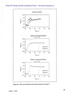
The applied motor‟s torque used to achieve the ensemble‟s movement can be measured,
obtaining figure 14.
The above graph shows the motor‟s torque that activates the cyclist's femur over the
simulation time. The graph shows that some values are negative, this is due to the motor´s
orientation, and that during the simulation, the values vary from negative to positive. This is
because the bicycle‟s movement on the velodrome is not constant, it accelerates at first, and
subsequently slows down. The maximum torque values generated during the simulation can
also be determined from the graph, and with the respective measurement of the femur´s angle
from the calf, the load is applied as a force applied to the part that fits with the socket of the
prosthesis (figure 15).
Figure 14. Torque exerted by a cyclist femur to generate movement
/>
320
Preprocessing a Static Finite Elements Simulation for a Transtibial Prosthesis Using CAE Tools
Figure 15. Model with applied forces in the finite element simulation.
6. CONCLUSIONS
This work demonstrates how computational tools facilitate the measurement of complex
parameters such as the load vector, necessary to carry out a finite element simulation. Some
aspects to highlight, and others to take into account, are the following:
Motion analysis allows the measurement of dynamic variables on a mechanism; however, it is
limited by the forces that it can take into account: inertial, body‟s, and friction. In the case of a
cyclist, there is a variable that cannot be taken into account: wind friction. In order to include
it, a tool that allows the quantification of this value can be used, and then apply it to the
motion analysis as a variable force over time.
Mass measurements and mass center locations are critical, and to obtain reliable results, it is
necessary to make such measurements and accurately locate the mass centers on different
parts of the system. It is not necessary to make a perfect modeling, since a simplified
modeling is enough, as long as the physical properties for each element represent exactly the
real values.
Motion analysis is a complex tool and a simulation with that tool takes a long time. In this
work, it was demonstrated with a small and simplified simulation, that the tool has the ability
to measure the forces applied from one system to another during a movement. In order to
obtain results that are consistent with reality, it is necessary that the trajectory, as well as the
time spent by the cyclist on making that trajectory, are the real ones; for the simulation shown
in this work, small values were used, since they allowed to lower the computational load of
the simulation. To be able to work with real values, machines with high-end hardware features
that support larger simulations are required.
ACKNOWLEDGEMENT
We would like to thank the Mechatronics Engineering program from Military Nueva Granada
University for the support given on carrying out this study.
REFERENCES
[1]
M. Zhang, A. F. T. Mak, and V. C. Roberts, “Finite element modelling of a residual
lower-limb in a prosthetic socket: A survey of the development in the first decade,” Med.
Eng. Phys., vol. 20, no. 5, pp. 360–373, 1998.
/>
321
Juan Sebastián Lasprilla, Hoffman F. Ramírez, Mauricio Mauledoux
[2]
F. J. and S. D.G., “Socket considerations for the patient with a transtibial amputation,”
Clin. Orthop. Relat. Res., no. 361, pp. 76–84, 1999.
[3]
T. Dumbleton et al., “Dynamic interface pressure distributions of two transtibial prosthetic
socket concepts,” J. Rehabil. Res. Dev., vol. 46, no. 3, pp. 405–416, 2009.
[4]
H. bo Jiang, “Static and Dynamic Mechanics Analysis on Artificial Hip Joints with
Different Interface Designs by the Finite Element Method,” J. Bionic Eng., vol. 4, no. 2,
pp. 123–131, 2007.
[5]
D. Lacroix and J. F. Ramírez Patiño, “Finite element analysis of donning procedure of a
prosthetic transfemoral socket,” Ann. Biomed. Eng., vol. 39, no. 12, pp. 2972–2983, 2011.
[6]
W. C. C. Lee, M. Zhang, X. Jia, and J. T. M. Cheung, “Finite element modeling of the
contact interface between trans-tibial residual limb and prosthetic socket,” Med. Eng.
Phys., vol. 26, no. 8, pp. 655–662, 2004.
[7]
M. C. Faustini, R. R. Neptune, and R. H. Crawford, “The quasi-static response of
compliant prosthetic sockets for transtibial amputees using finite element methods,” Med.
Eng. Phys., vol. 28, no. 2, pp. 114–121, 2006.
[8]
P. K. Lenka and A. R. Choudhury, “Analysis of trans tibial prosthetic socket materials
using finite element method,” J. Biomed. Sci. Eng., vol. 04, no. 12, pp. 762–768, 2011.
[9]
X. Jia, M. Zhang, and W. C. C. Lee, “Load transfer mechanics between trans-tibial
prosthetic socket and residual limb - Dynamic effects,” J. Biomech., vol. 37, no. 9, pp.
1371–1377, 2004.
[10]
M. Omasta, D. Paloušek, T. Návrat, and J. Rosický, “Finite element analysis for the
evaluation of the structural behaviour, of a prosthesis for trans-tibial amputees,” Med.
Eng. Phys., vol. 34, no. 1, pp. 38–45, 2012.
[11]
F. C. Sup and M. Goldfarb, “Design of a Pneumatically Actuated Transfemoral
Prosthesis,” pp. 1419–1428, 2008.
[12]
P. T. Mecánica Plástica, “Ficha Técnica Uhmw,” 2017.
[13]
C. F. Deportiva, “Dimensiones y Especificaciones de Zonas Deportivas,” vol. 1, p. 177,
2017.
[14]
S. Pineda Ledezma, “Proceso de fabricacion de ortesis tipo kafo y protesis trasfemoral
endoesqueletica con cuenca ovolongitudinal,” Universidad Don Bosco, 2006.
[15]
J. E. Zamudio Palacios et al., “Modelo dinámico de una prótesis transtibial para ciclistas
paralímpicos,” Memorias Congr. UTP, vol. 1, no. 1, pp. 151–157, 2018.
[16]
F. J. Gesé Bordils, “Estudio mediante elementos finitos de los esfuerzos producidos en
una biela de bicicleta,” Universidad Carlos III De Madrid Escuela Politécnica Superior,
2013.
/>
322