Embedded Control Applications Using AT89S52
Bạn đang xem bản rút gọn của tài liệu. Xem và tải ngay bản đầy đủ của tài liệu tại đây (840.27 KB, 44 trang )
Chapter 6
Embedded Control Applications Using
AT89S52
This chapter is a complete diversion from the PIC16F877. Here we are back to a
very popular CISC architecture i.e. Atmel 89S52. Let us justify the reasons for the
departure from what follows right away since Chapter 2. At the outset, we submit
that the talk of the town “RISC versus CISC debate” has almost come to an end with
the state of art complex microprocessor architectures, ASICs and commercial off-
the-shelf (COTS) architectures. However, the market statistics won’t forgive us if we
ignore the fact that today the MCS51 series accounts for the more than 25% of the
8 bit Microcontroller worldwide market, with part volumes exceeding 100,000,000
or more units per annum. We must give justice to the investment to the tune of
billions of dollars and most importantly programming expertise that comes from
millions of programmer hours apart from the efforts taken to launch full proof IDEs,
compliers, debuggers and other tools. Therefore we have taken the most popular
representative sample of MCS51 series i.e. Atmel 89S52 for the applications
chosen in this chapter. Following case studies are developed in this chapter:
6.1
Night Lamp Controller
6.2
Microcontroller Based Control for Nylon Rubber Stamp Making Machine
Control
6.3
A Tiny BIOS or Diagnostic Interface with MCS51
6.4
Simple Digital IC Tester
6.5
Microcontroller Based Salinity Measurement System
6.6
Fault Tolerant Sensor Interface
6.7
Sensor Matrix Interface
6.8
Design Micricontroller Based Servo Controller
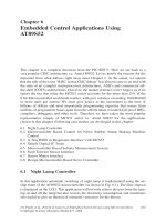
6.1 Night Lamp Controller
In this application automatic switching of night lamp is implemented using the on-
chip timer of the AT89S52 microcontroller (as shown in Fig. 6.1). The time elapsed
is displayed on the LCD. This application will not only relieve the user from the turn-
ing on and off the lamp but also lessens the electricity consumption and sometimes
also useful to give an illusion of someone’s presence for the thieves.
J.S. Parab, et al., Practical Aspects of Embedded System Design using Microcontrollers, 103
© Springer Science + Business Media B.V. 2008
104 6 Embedded Control Applications Using AT89S52
A slight modification by introducing a light sensing module will make this cir-
cuit fully automatic.
Program 6.1
Night lamp controller
Program Source Code
*****************************************************************
// Program illustrates the Night lamp controller using the microcontroller.
—————————————————————————————————
#include <REG52.H> /* special function register declarations */
/* for the intended 8051 derivative */
sbit RS = P2
∧
0; // LCD Initialization signals
sbit RW = P2
∧
1;
sbit EL = P2
∧
2;
sbit Relay = P2
∧
3; // Relay connected to P2.3 pin of the
controller
sbit R1 = P3
∧
0; //Key board signals
sbit R2 = P3
∧
1;
sbit R3 = P3
∧
2;
Fig. 6.1
Circuit diagram for night light controller using 89S52 microcontroller
sbit R4= P3
∧
3;
sbit C1 = P3
∧
4;
sbit C2 = P3
∧
5;
sbit C3 = P3
∧
6;
sbit C4 = P3
∧
7;
void Delay(int);
void INIT(void);
void ENABLE(void);
void LINE(int);
int keyb(void);
void settime(void);
void starttimer(void);
void check_timeout(int);
int settime1=10; // Default time
int set_temp;
void settime(void) // Routine to set time to keep the lamp on
{
int ten_pos=0, unit_pos=0;
while(!(ten_pos=keyb() ) );
while(!(unit_pos=keyb() ) );
P1=( ( (ten_pos) )+0×30);
ENABLE();
P1=( (unit_pos)+0×30);
ENABLE();
Delay(2000);
settime1= ten_pos
*
10 + unit_pos;
}
void starttimer()
{
Relay=1; // Turn on the Lamp
set_temp= settime1;
check_timeout(set_temp);
set_temp−;
P1=( ( (set_temp)/10)+0×30); // display the remaining time on LCD
ENABLE();
P1=( (set_temp/10)%10+0×30); // display the remaining time on LCD
ENABLE();
Delay(2000);
}
void check_timeout(g) // check if count is zero and according
switch off the Lamp
{
if(g == 0)
{
Relay=0; // turn off the Lamp
6.1 Night Lamp Controller 105
106 6 Embedded Control Applications Using AT89S52
}
}
void main(void)
{
char test[]=“Night lamp controller”;
char code set_msg[]=“ 1-> set time”;
char code start_msg[]=“ 2-> start timer ”;
char
*
p;
int j;
INIT(); // Initaialization routine for LCD
LINE(1);
p=&test;
for(j=0;j<17;j++)
{
if(j==0)LINE(1);
if(j==8)LINE(2);
P1=
*
p++;
ENABLE();
Delay(200);
}
while(1){
RS = 1;
p=&set_msg;
for(j=0;j<17;j++)
{
if(j==0)LINE(1);
if(j==8)LINE(2);
P1=
*
p++;
ENABLE();
Delay(200);
}
RS = 1;
p=&start_msg;
for(j=0;j<17;j++)
{
if(j==0)LINE(1);
if(j==8)LINE(2);
P1=
*
p++;
ENABLE();
Delay(200);
}
j=0;
j=keyb();
if(j>0);
if(j==1){ // if key 1 is pressed then set the timer to
keep the Lamp oN
settime();
}
if(j==2){ // if key 2 is pressed then start the timer to
count in down mode
starttimer();
}
}
}
void Delay(int k) // Dealay routine
{
int i,j;
for (j=0;j<k+1;j++){
for (i=0;i<100;i++);
}}
void ENABLE(void)
{
EL=1;
Delay(1);
EL=0;
Delay(1);
}
void LINE(int i){
if (i==1) {
RS=0;
RW=0;
P1=0×80;
ENABLE();
RS=1;
}
else
{
RS=0;
RW=0;
P1=0×C0;
ENABLE();
RS=1;
}
}
void INIT(void)
{
RS=0;
RW=0;
EL=0;
6.1 Night Lamp Controller 107
108 6 Embedded Control Applications Using AT89S52
P1 = 0×38;
ENABLE();
ENABLE();
ENABLE();
ENABLE();
P1 = 0×06;
ENABLE();
P1 = 0×0E;
ENABLE();
P1 = 0×01;
ENABLE();
}
int keyb(void){
int key=0;
C1=1;
C2=1;C3=1;C4=1;R1=0;R2=1;R3=1;R4=1;
if (C1==0) key = 1;
if (C2==0) key = 2;
if (C3==0) key = 3;
if (C4==0) key = 4;
return(key);
}
*****************************************************************
6.2 Microcontroller Based Control for Nylon Rubber Stamp
Making Machine
Rubber stamping is a craft in which some type of ink made of dye or pigment is
applied to an image or pattern that has been carved, molded, laser engraved or vul-
canized, onto a sheet of rubber. Spanish explorers were pioneers in developing this
“sticky substance” that bounced, used by South American Indians. In 1736, Charles
Marie de la Condamine, a French scientist studying the Amazon, sent a piece of
“India Rubber” back to France [71]. With the widespread use of the rubber stamps,
there are good number of manufacturers making the machines for rubber stamps
[72]. Most of these machines are based on the vulcanizing press mechanism. It is
the most cost effective methods of making rubber stamps and leads to cost effec-
tiveness especially in case of mass produced stamps. In this process a batch of
stamps is produced using a mould. For making the mould a standard process is
adopted. The first step is making a master plate manufactured from metal or poly-
mer. The master plate comprises of the necessary artwork/text to be used for mak-
ing an impression in the mould. Thus made master plate is then pressed into the
matrix board which further acts on the rubber. A definite cycle of heat and pressure
is applied to the master plate and matrix board inside a Vulcanizing press. With this
the Matrix follows the shape of the artwork/text provided by the master plate,
which subsequently hardens on cooling. Once the mould is ready as per the above
process, the raw rubber stamp gum is placed on top of the mould and then placed
inside the stamp press. Hydraulic pressure is placed upon the rubber and the mould
from within the stamp press causing the rubber to melt into the areas of the mould
that contain the images and text, curing and hardening takes about 10 min. Once
cured the sheet of rubber is pulled away from the mould and cut up into individual
stamps to be affixed to mounts [73].
Most of the rubber stamp making machines has a built in mechanism to accom-
plish the manufacturing process described above. However, for following this proc-
ess an experienced human operator is required which will decide the pressure and
temperature cycles to be applied? In this application we have automated the entire
process by incorporating the 89S52 microcontroller based system design that will
suffice most of the manual rubber stamp making machines.
The microcontroller based automation as shown in Fig. 6.2, leads to certain definite
advantages such as consistency, less manufacturing time and simplified operation. The
consistency is achieved with the exact application of downward pressure and dwell-
time set by the thumbwheel switches. The hot-stamping operation is also completed
within a very short amount of time with exact application of the power through the
relay mechanism. The LCD display not only ensures the ease of operation, but also
provides some valuable information such as the number of imprints completed, proc-
ess temperature and pressure. The operation commences with the application of paddle
operated switch.
Fig. 6.2
Microcontroller based control for nylon rubber stamp making machine
6.2 Microcontroller Based Control for Nylon Rubber Stamp Making Machine 109
110 6 Embedded Control Applications Using AT89S52
Program 6.2
Microcontroller based control for nylon rubber stamp making
machine
Program Source Code
*****************************************************************
/* Program Illustrate the Microcontroller 89S52 based control for Nylon Rubber
Stamp Making Machine.*/
—————————————————————————————————-
#include <REG52.H> /* special function register declarations */
/* for the intended 8051 derivative */
#include <stdio.h> /* prototype declarations for I/O functions */
sbit RS = P2
∧
0;
sbit RW = P2
∧
1;
sbit EN = P2
∧
2;
sbit Sw1= P2
∧
3;
sbit RL=P3
∧
5;
sbit dat=P3
∧
6;
sbit clk= P3
∧
7;
unsigned int unit,ten,hundred,tenth,tens,tenthou,thousand;
void delay(int); /* Stop Exection with Serial Intr. */
void INIT(void);
void ENABLE(void);
void LINE(int);
void display(char );
void clear(void);
void delay(void);
char
seq[16]={0XC0,0XF9,0XA4,0XB0,0X99,0X92,0X82,0XF8,0X80,0X90,0X88,
0X80,0XC6,0XC0,0X86,0X8E};
void main (void) {
int i,N;
while (1) {
N=P1;
if (Sw1==0)
{
unit =(N%10);
ten=(N/10)%10;
hundred=(N/100)%10;
tenth=(N/1000);
clear();
display (seq[tenth]);
display (seq[hundred]);
display (seq[ten]);
display (seq[unit]);
INIT();
LINE(1);
P1=tenthou;
ENABLE();
P1=thousand;
ENABLE();
P1=hundred;
ENABLE();
P1=tens;
ENABLE();
P1=unit;
ENABLE();
RL=1;
delay ();
clear ();
}
else
{
for (i=N; i>=0;i–)
{ unit =(N%10);
ten=(N/10)%10;
hundred=(N/100)%10;
tenth=(N/1000);
clear();
display (seq[ten]);
display (seq[unit]);
delay();
INIT();
LINE(1);
P1=tenthou;
ENABLE();
P1=thousand;
ENABLE();
P1=hundred;
ENABLE();
P1=tens;
ENABLE();
P1=unit;
ENABLE();
}
RL=0;
}
}
}
void LINE(int i){
if (i==1) {
RS=0;
6.2 Microcontroller Based Control for Nylon Rubber Stamp Making Machine 111
112 6 Embedded Control Applications Using AT89S52
RW=0;
P1=0×80;
ENABLE();
RS=1;
}
else
{
RS=0;
RW=0;
P1=0×C0;
ENABLE();
RS=1;
}
}
void delay()
{
int i,j;
for (j=0;j<10;j++){
for (i=0;i<100;i++);
}}
void ENABLE(void)
{
EN=1;
delay();
EN=0;
delay();
}
void INIT(void)
{
RS=0; /*initialization of LCD display*/
RW=0;
EN=0;
P1 = 0×38;
ENABLE();
ENABLE();
ENABLE();
ENABLE();
P1 = 0×06;
ENABLE();
P1 = 0×0E;
ENABLE();
P1 = 0×01;
ENABLE();
}
void display(char k)
{
unsigned char mask;
int i;
mask=0X80;
for(i=0;i<8;i++)
{
if(k&mask)
dat=1;
else
dat=0;
clk=0;
clk=1;
clk=0;
mask=mask>>1;
}
}
void clear(void)
{
int i;
for (i=0;i<33;i++)
{
dat=1;
clk=0;clk=1;clk=0;
}
}
*****************************************************************
6.3 A Tiny BIOS or Diagnostic Interface with MCS51
BIOS, in computing, stands for Basic Input/Output System that refers to the soft-
ware code run by a computer after powered on. Its primary function is to prepare
the machine so other software programs stored on various media (such as hard
drives, floppies, and CDs) can load, execute, and assume control of the computer.
In this case study a program is developed in which few I/O routines like LCD
interfacing, keyboard interfacing, etc. have been developed as per the BIOS style of
coding. It is organized in such a way that the information such as port addresses,
characters to be displayed are passed as parameters to the interrupt service routine.
Program 6.3
A tiny BIOS or diagnostic interface with MCS51 (Refer
Fig. 6.3)
Program Source Code
*****************************************************************
/* Program to illustrate the Tiny BIOS interface with the Microcontroller 89S52.*/
6.3 A Tiny BIOS or Diagnostic Interface with MCS51 113
114 6 Embedded Control Applications Using AT89S52
—————————————————————————————————
#include <REG52.H> /* special function register declarations */
/* for the intended 8051 derivative */
#include <stdio.h> /* prototype declarations for I/O functions */
sbit RS = P2
∧
0;
sbit RW = P2
∧
1;
sbit EL = P2
∧
2;
sbit Relay = P2
∧
4;
sbit R1 = P0
∧
0;
sbit R2 = P0
∧
1;
sbit R3 = P0
∧
2;
sbit R4 = P0
∧
3;
sbit C1 = P0
∧
4;
sbit C2 = P0
∧
5;
sbit C3 = P0
∧
6;
sbit C4 = P0
∧
7;
char array[]=“EMBEDDED C PROGRAMMING IS INTERRESTING ”;
void Delay(int);
void INIT(void);
void ENABLE(void);
void LINE(int);
int keyb(void);
char getascii(int);
Fig. 6.3
A tiny BIOS or diagnostic interface with MCS51
char getascii(int k)
{
int ascii;
if(k<10)
ascii=k+0×30;
if (k==10) ascii=0×30;
return (ascii);
}
int keyb(void){
int key=0;
C1=1;
C2=1;
C3=1;
C4=1;
R1=0;
R2=1;
R3=1;
R4=1;
if (C1==0) key = 1;
if (C2==0) key = 2;
if (C3==0) key = 3;
if (C4==0) key = 4;
R1=1;
R2=0;
R3=1;
R4=1;
if (C1==0) key = 5;
if (C2==0) key = 6;
if (C3==0) key = 7;
if (C4==0) key = 8;
R1=1;
R2=1;
R3=0;
R4=1;
if (C1==0) key = 9;
if (C2==0) key = 10;
if (C3==0) key = 11;
if (C4==0) key = 12;
R1=1;
R2=1;
R3=1;
R4=0;
if (C1==0) key = 13;
if (C2==0) key = 14;
if (C3==0) key = 15;
6.3 A Tiny BIOS or Diagnostic Interface with MCS51 115
116 6 Embedded Control Applications Using AT89S52
if (C4==0) key = 16;
return(key);
}
void LINE(int i)
{
if (i==1)
{
RS=0;
RW=0;
P1=0×80;
ENABLE();
RS=1;
}
else
{
RS=0;
RW=0;
P1=0×C0;
ENABLE();
RS=1;
}
}
void Delay(int k)
{
int i,j;
for (j=0;j<k+1;j++)
{
for (i=0;i<10000;i++);
}
}
void ENABLE(void)
{
EL=1;
Delay(1);
EL=0;
Delay(1);
}
void INIT(void) /*initialization of LCD display*/
{
RS=0;
RW=0;
EL=0;
P1 = 0×38;
ENABLE();
ENABLE();
ENABLE();
ENABLE();
P1 = 0×06;
ENABLE();
P1 = 0×0E;
ENABLE();
P1 = 0×01;
ENABLE();
}
void main (void)
{
char b;
int j;
while (1)
{
j=0;
j = keyb();
if (j!=0){
if (j==1) // display on LCD is enabled
{
INIT();
LINE (1);
for (b=0;b<30;b++)
{
if (b==8)
LINE(2);
P1=array[b];
ENABLE();
}
RS=0;
P1=0×01;
ENABLE();
RS=1;
LINE(1);
for (b=16;b<33;b++)
{
if (b==24)
LINE(2);
P1=array[b];
ENABLE();
}
}
else if (j==2)
6.3 A Tiny BIOS or Diagnostic Interface with MCS51 117
118 6 Embedded Control Applications Using AT89S52
{
Relay=1; //‘switch on the relay
Delay(10000);
Relay=0; // switch off the relay after 10 s
}
//else if(j==3)
//{
//activate some other peripherals like LEDs, HyperTerminal communication, serial
7 SEG, etc.
//}
} }
}
*****************************************************************
Note: Many monitor routine may be added on similar lines.
6.4 Simple Digital IC Tester for 74XX Series
Digital IC testing is by itself a completely different philosophy. In this case study
we have employed AT89S52 for the testing purpose. The basic approach is based
on table lookup of the truth tables which are invoked based on the IC the type of
the IC inserted in the socket. User has to specify the IC number by entering through
the keyboard such as key1 corresponds to 7400, key2 to 7408, etc.
By interfacing additional external memory one can modify the application for
testing more digital ICs. Fig. 6.4 shows the block schematic while the circuit dia-
gram is as per Fig. 6.5.
Fig. 6.4
Block diagram of simple digital IC tester for the 74XX series
6.4 Simple Digital IC Tester for 74XX Series 119
Fig. 6.5
Schematic of simple digital IC tester for 74XX series
Program 6.4
Simple digital IC tester for the 74XX series
Program Source Code
**********************************************************************
/* Program illustrates the Simple Digital IC tester for 74XX series using 89S52
microcontroller*/
———————————————————————————————————-
#include <REG52.H> /* special function register declarations */
#include <stdio.h> /* for the intended 8051 derivative */
sbit RS = P2
∧
0;
sbit RW = P2
∧
1;
sbit EL = P2
∧
2;
sbit R1 = P0
∧
0;
sbit R2 = P0
∧
1;
sbit R3 = P0
∧
2;
sbit R4 = P0
∧
3;
sbit C1 = P0
∧
4;
sbit C2 = P0
∧
5;
sbit C3 = P0
∧
6;
sbit C4 = P0
∧
7;
sbit a = P2
∧
3;
sbit b= P2
∧
4;
sbit c = P2
∧
5;