Legacy Support for USB Keyboards and Mice and the Host Controller Driver
Bạn đang xem bản rút gọn của tài liệu. Xem và tải ngay bản đầy đủ của tài liệu tại đây (125.6 KB, 9 trang )
Legacy Support for USB Keyboards and Mice
and the Host Controller Driver
Microsoft Corporation
December 3, 1998
The operating system brings a Universal Serial Bus (USB) host controller to an
operational state using the following steps:
1* Load the host controller driver and find the host controller.
2* Verify the host controller and allocate system resources.
3* Take control of the host controller.
4* Set up host controller registers and host controller communications area
(HCCA).
5* Start sending Start of Frame (SOF) tokens on the USB.
This article examines the third step of the process—taking control of the host
controller—in the context of providing a solution to the problem of legacy keyboard
and mouse support when a USB keyboard, mouse, or both are attached to the PC. The
information in this article applies to both Microsoft® Windows® 98 and Windows
2000.
USB support in Windows 98 and Windows 2000 is designed based on these
assumptions:
6* System vendors want to support USB keyboards and mice when the BIOS has
control of the system (for example, the USB keyboard works when the BIOS
Setup program is running or the system is running in MS-DOS® mode).
7* Host controller hardware and firmware vendors provide some amount of
support for the emulation of PS/2-compatible keyboards and mice by USB
keyboards and mice.
Under conditions where these assumptions are met, this article describes the way
Windows host controller drivers hand off USB keyboard and mouse interrupt
processing between the operating system and the BIOS. The implementations used by
the Open Host Controller Interface (OHCI) host controller driver and Universal Host
Controller Interface (UHCI) host controller driver differ because of fundamental
differences in the OHCI and UHCI specifications. Both implementations are
described in this article.
The operating system/BIOS handoff of legacy keyboard and mouse support is a two-
way process. In other words, the handoff can occur from the BIOS to the operating
system or from the operating system to the BIOS. Both handoff directions are
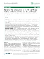
described in this article. An example sequence of events that involves handoff of the
host controller in both directions is shown in Figure 1.
Figure 1. Example sequence of events in handoff of the host controller
The time line in Figure 1 starts with a power-up (cold boot) event on the PC.
8* Immediately after power-up and for some period of time, the BIOS controls
the PC and the host controller. During this time interval, a user should be able
to use a USB keyboard to enter BIOS Setup and use all keys on the USB
keyboard that are valid during BIOS Setup.
9* If the user does not choose to enter BIOS Setup, the BIOS starts the operating
system at some point and the operating system takes control of the PC and the
host controller. As shown in Figure 1, code in a routine in the operating system
host controller driver performs the necessary steps to hand off control of the
legacy keyboard support function from the BIOS to the operating system host
controller driver (in this article, that routine is called StopBIOS).
10* The next event shown in Figure 1 occurs when the user employs the
Shutdown menu to shut down to MS-DOS. This causes the host controller
driver to be unloaded; before unloading, it executes a routine that performs the
necessary steps to hand off control of the legacy keyboard support function to
the BIOS (in this article, that host controller driver routine is called
StartBIOS).
Hand Off for the OHCI Host Controller
The host controller driver is responsible for a per-host controller set of data called
device data. At startup and shutdown, the host controller driver manages the host
controller through a set of Operational Registers. These registers are part of the host
controller and are accessed by the host controller driver using memory references
through a noncached virtual pointer.
As defined in the OHCI specification, legacy keyboard and mouse emulation is
provided by a set of registers controlled by code running in System Management
Mode (SMM). When data is received from the keyboard or mouse, the SMM
emulation code is notified and translates the USB keyboard/mouse data into a data
sequence that is equivalent to what would be produced by a PS/2-compatible
keyboard/mouse interface. This emulation scheme is described in the "Operational
Theory" section of Appendix B in the OHCI specification.
Interrupts generated by the host controller emulation hardware when USB keyboard
or mouse data is received are steered by the host controller hardware to either a
system management interrupt (SMI) or the standard host controller interrupt. The
host controller uses these rules to steer the interrupt:
11* When the InterruptRouting bit in the host controller HcControl
register is cleared, interrupts are steered to the standard host controller
interrupt.
12* When the InterruptRouting bit is set, interrupts are steered to the SMI
interrupt.
Note SMM is a processor mode in Intel® Architecture platforms that is transparent to
the operating system and application software. SMM is intended for use only by
firmware. SMM is one of the processor's major operating modes, on a level with
protected mode, real-address mode, or virtual-86 mode. An external signal, SMI#,
causes the processor to switch to SMM; this is known as the SMI interrupt. The SMI#
signal might be generated, for example, by closing the lid of a portable computer.
When the processor recognizes an SMI# signal, the processor waits for all stores to
complete and saves state. Then the processor begins to execute the SMM handler in
firmware.
Power-Up Processes
The SMM driver gets control of the processor before any other driver. The SMM
driver must set the InterruptRouting bit to cause all host controller interrupts to be
routed to the SMI interrupt. The SMM driver then sets system-specific fields in the
host controller registers, waits at least the minimum time specified in the USB
Specification for assertion of reset on the USB, and then sets up the host controller.
Operating System Takes Control of the OHCI Host
Controller
Later, when the host controller driver is loaded and running, it can determine that the
SMM driver is active because the InterruptRouting bit is set in the HcControl
register. When it wants the interrupts steered to the standard host controller interrupt,
the host controller driver sets the OwnershipChangeRequest bit in the
HcCommandStatus register, then monitors the InterruptRouting bit to determine
when the ownership change has taken effect.
The following pseudocode shows the structure and logic of the entire StopBIOS
routine in the Windows OHCI host controller driver.
Notice that the StopBIOS routine is called from only one place in the host controller
driver, from the OpenHCI_InitializeHardware routine.
Get a pointer to a per-device, per-host controller data structure
If InterruptRouting bit is set to 1 // SMM driver owns host controller.
Set OwnershipChangeRequest bit
While total time elapsed is less than 0.5 seconds
Wait 1 ms
Read InterruptRouting bit
If InterruptRouting bit is cleared //SMM has relinquished
ownership.
Set LEGACY_BIOS_DETECTED bit in per-device, per-host data
structure
Return (STATUS_SUCCESSFUL)
Endif
Endwhile // 0.5 sec have elapsed and SMM has not relinquished control.
Endif
Return (STAUS_UNSUCCESSFUL)
Note that a return of STATUS_UNSUCCESSFUL can result in a Code 10 message
appearing in the Device Manager entry for the OHCI host controller.
BIOS Takes Control of the OHCI Host Controller
The following pseudocode shows the structure and logic of the entire StartBIOS
module in the Windows OHCI host controller driver. Notice that the StartBIOS
routine is called only after the host controller driver will not touch the hardware
again.
Get pointer to per-device, per-host controller data structure
If LEGACY_BIOS_DETECTED flag set in per-device, per-host controller data
structure
//hand back control of host controller to SMM driver.
Set OwnershipChangeRequest bit in HcCmd register
Set OwnershipChange interrupt enable bit in HcInt register
Set MasterInterruptEnable bit in HcInt register
Endif
Return(STATUS_SUCCESSFUL)
Hand Off for the UHCI Host Controller
Section 5 of the Universal Host Controller Interface (UHCI) Design Guide,
Revision 1.1 gives an example implementation of mouse and keyboard legacy
support and describes one way to hand off control of the host controller between the
BIOS and the UHCI host controller driver in the operating system. The key UHCI
register used in the example is the legacy support register (LEGSUP). For
implementers in a PCI device, the LEGSUP register is located at offset C0-C1h, in
function 2 PCI configuration space.
The Microsoft UHCI host controller driver also uses the LEGSUP register as the
primary interface in implementing the handoff of the host controller between the
operating system and the BIOS; the Microsoft host controller driver implementation
logic is described in this section of the article.
LEGSUP register structure. The LEGSUP register is a bitmap containing 16 bits.
The meaning of each of the 16 bits is fully specified in Section 5 of the Universal
Host Controller Interface (UHCI) Design Guide, Revision 1.1. A summary
description is given in the following table so the reader can interpret the bitmap
constant values used in later sections of this article without referring to the Design
Guide.
Table 1. LEGSUP register structure
Bit Name Description
15 (R/WC) A20PTS
1 = A20GATE passthrough sequence has
ended.
14 Reserved.
13 (R/W) USBPIRQDEN
1 = USB interrupt is routed to PIRQD
(default). 0 = Not routed to PIRQD. This bit
can be used to prevent the host controller from
generating an interrupt.
12 (RO) USBIRQS 1 = USB IRQ is active.
11 (R/WC) TBY64W 1 = Write to port 64h has occurred.
10 (R/WC) TBY64R 1 = Read to port 64h has occurred.
9 (R/WC) TBY60W 1 = Write to port 60h has occurred.
8 (R/WC) TBY60R 1 = Read to port 60h has occurred.
7 (R/W) SMIEPTE
1 = Enable generation of an SMI when
A20GATE passthrough sequence has ended.
0 = Disable (default).
6 (RO) PSS
1 = A20GATE passthrough sequence is
currently in progress.
0 = Not executing (default).
5 (R/W) A20PTEN
1 = Enable A20GATE passthrough sequence.
0 = Disable (default).
4 (R/W) USBSMIEN
1 = Enable SMI# generation on USB IRQ.
0 = Disable (default).
3 (R/W) 64WEN
1 = Enable I/O Trap and SMI# generation of
port 64h write.
0 = Disable (default).