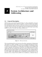
GSM switching services and protocols P6
Bạn đang xem bản rút gọn của tài liệu. Xem và tải ngay bản đầy đủ của tài liệu tại đây (648.53 KB, 30 trang )
Coding, Authentication, and
Ciphering
The previous chapter explained the basic functions of the physical layer at the air interface,
e.g. the de®nition of logical and physical channels, modulation, multiple access techni-
ques, duplexing, and the de®nition of bursts. In this chapter, we discuss several additional
functions that are performed to transmit the data in an ef®cient, reliable, and secure way
over the radio channel: source coding and speech processing (Section 6.1), channel coding
and burst mapping (Section 6.2), and security related functions, such as encryption and
authentication (Section 6.3).
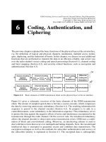
Figure 6.1 gives a schematic overview of the basic elements of the GSM transmission
chain. The stream of sampled speech data is fed into a source encoder, which compresses
the data by removing unnecessary redundancy (Section 6.1). The resulting information bit
sequence is passed to the channel encoder (Section 6.2). Its purpose is to add, in a
controlled manner, some redundancy to the information sequence. This redundancy serves
to protect the data against the negative effects of noise and interference encountered in the
transmission through the radio channel. On the receiver side, the introduced redundancy
allows the channel decoder to detect and correct transmission errors. GSM uses a combi-
nation of block and convolutional coding. Moreover, an interleaving scheme is used to
deal with burst errors that occur over multipath and fading channels. Next, the encoded and
interleaved data is encrypted to guarantee secure and con®dent data transmission. The
encryption technique as well as the methods for subscriber authentication and secrecy of
the subscriber identity is explained in Section 6.3. The encrypted data is subsequently
6
Figure 6.1: Basic elements of GSM transmission chain on the physical layer at the air interface
GSM Switching, Services and Protocols: Second Edition. Jo
È
rg Eberspa
È
cher,
Hans-Jo
È
rg Vo
È
gel and Christian Bettstetter
Copyright q 2001 John Wiley & Sons Ltd
Print ISBN 0-471-49903-X Online ISBN 0-470-84174-5
mapped to bursts (Section 6.2.4), which are then multiplexed as explained in the previous
chapter. Finally the stream of bits is differential coded and modulated.
After transmission, the demodulator processes the signal, which was corrupted by the
noisy channel. It attempts to recover the actual signal from the received signal. The
next steps are demultiplexing and decryption. The channel decoder attempts to reconstruct
the original information sequence, and, as a ®nal step, the source decoder tries to recon-
struct the original source signal.
6.1 Source Coding and Speech Processing
Source coding reduces redundancy in the speech signal and thus results in signal compres-
sion, which means that a signi®cantly lower bit rate is achieved than needed by the original
speech signal. The speech coder/decoder is the central part of the GSM speech processing
function, both at the transmitter (Figure 6.2) as well as at the receiver (Figure 6.3). The
functions of the GSM speech coder and decoder are usually combined in one building
block called the codec (COder/DECoder).
The analog speech signal at the transmitter is sampled at a rate of 8000 samples/s, and
the samples are quantized with a resolution of 13 bits. This corresponds to a bit rate of
104 kbit/s for the speech signal. At the input to the speech codec, a speech frame contain-
ing 160 samples of 13 bits arrives every 20 ms. The speech codec compresses this speech
signal into a source-coded speech signal of 260-bit blocks at a bit rate of 13 kbit/s. Thus the
GSM speech coder achieves a compression ratio of 1 to 8. The source coding procedure is
brie¯y explained in the following; detailed discussions of speech coding procedures are
given in [54].
A further ingredient of speech processing at the transmitter is the recognition of speech
pauses, called Voice Activity Detection (VAD). The voice activity detector decides, based
on a set of parameters delivered by the speech coder, whether the current speech frame
(20 ms) contains speech or a speech pause. This decision is used to turn off the transmitter
6 Coding, Authentication, and Ciphering
96
Figure 6.2: Schematic representation of speech functions at the transmitter
ampli®er during speech pauses, under control of the Discontinuous Transmission (DTX)
block.
The discontinuous transmission mode takes advantage of the fact, that during a normal
telephone conversation, both parties rarely speak at the same time, and thus each direc-
tional transmission path has to transport speech data only half the time. In DTX mode, the
transmitter is only activated when the current frame indeed carries speech information.
This decision is based on the VAD signal of speech pause recognition. The DTX mode can
reduce the power consumption and hence prolong the battery life. In addition, the reduc-
tion of transmitted energy also reduces the level of interference and thus improves the
spectral ef®ciency of the GSM system. The missing speech frames are replaced at the
receiver by a synthetic background noise signal called Comfort Noise (Figure 6.3). The
parameters for the Comfort Noise Synthesizer are transmitted in a special Silence Descrip-
tor (SID) frame.
This silence descriptor is generated at the transmitter from continuous measurements of the
(acoustic) background noise level. It represents a speech frame which is transmitted at the
end of a speech burst, i.e. at the beginning of a speech pause. In this way, the receiver
recognizes the end of a speech burst and can activate the comfort noise synthesizer with the
parameters received in the SID frame. The generation of this arti®cial background noise
prevents that in DTX mode the audible background noise transmitted with normal speech
bursts suddenly drops to a minimal level at a speech pause. This modulation of the back-
ground noise would have a very disturbing effect on the human listener and would signif-
icantly deteriorate the subjective speech quality. Insertion of comfort noise is a very
effective countermeasure to compensate for this so-called noise-contrast effect.
Another loss of speech frames can occur, when bit errors caused by a noisy transmission
channel cannot be corrected by the channel coding protection mechanism, and the block is
received at the codec as a speech frame in error, which must be discarded. Such bad speech
frames are ¯agged by the channel decoder with the Bad Frame Indication (BFI). In this
case, the respective speech frame is discarded and the lost frame is replaced by a speech
6.1 Source Coding and Speech Processing
97
Figure 6.3: Schematic representation of speech functions at the receiver
frame which is predictively calculated from the preceding frame. This technique is called
Error Concealment. Simple insertion of comfort noise is not allowed. If 16 consecutive
speech frames are lost, the receiver is muted to acoustically signal the temporary failure of
the channel.
The speech compression takes place in the speech coder. The GSM speech coder uses a
procedure known as Regular Pulse Excitation± Long-Term Prediction± Linear Predictive
Coder (RPE-LTP). This procedure belongs to the family of hybrid speech coders. This
hybrid procedure transmits part of the speech signal as the amplitude of a signal envelope,
a pure wave form encoding, whereas the remaining part is encoded into a set of parameters.
The receiver reconstructs these signal parts through speech synthesis (vocoder technique).
Examples of envelope encoding are Pulse Code Modulation (PCM) or Adaptive Delta
Pulse Code Modulation (ADPCM). A pure vocoder procedure is Linear Predictive Coding
(LPC). The GSM procedure RPE-LTP as well as Code Excited Linear Predictive Coding
(CELP) represent mixed (hybrid) approaches [15,46,54].
A simpli®ed block diagram of the RPE-LTP coder is shown in Figure 6.4. Speech data
generated with a sampling rate of 8000 samples/s and 13 bit resolution arrive in blocks of
160 samples at the input of the coder. The speech signal is then decomposed into three
components: a set of parameters for the adjustment of the short-term analysis ®lter (LPC)
6 Coding, Authentication, and Ciphering
98
Figure 6.4: Simpli®ed block diagram of the GSM speech coder
also called re¯ection coef®cients; an excitation signal for the RPE part with irrelevant
portions removed and highly compressed; and ®nally a set of parameters for the control of
the LTP long-term analysis ®lter. The LPC and LTP analyses supply 36 ®lter parameters
for each sample block, and the RPE coding compresses the sample block to 188 bits of
RPE parameters. This results in the generation of a frame of 260 bits every 20 ms,
equivalent to a 13 kbit/s GSM speech signal rate.
The speech data preprocessing of the coder (Figure 6.4) removes the DC portion of the
signal if present and uses a preemphasis ®lter to emphasize the higher frequencies of the
speech spectrum. The preprocessed speech data is run through a nonrecursive lattice ®lter
(LPC ®lter, Figure 6.4) to reduce the dynamic range of the signal. Since this ®lter has a
``memory'' of about 1 ms, it is also called short-term prediction ®lter. The coef®cients of
this ®lter, called re¯ection coef®cients, are calculated during LPC analysis and transmitted
in a logarithmic representation as part of the speech frame, Log Area Ratios (LARs).
Further processing of the speech data is preceded by a recalculation of the coef®cients of
the long-term prediction ®lter (LTP analysis in Figure 6.4). The new prediction is based on
the previous and current blocks of speech data. The resulting estimated block is ®nally
subtracted from the block to be processed, and the resulting difference signal is passed on
to the RPE coder.
After LPC and LTP ®ltering, the speech signal has been redundancy reduced, i.e. it already
needs a lower bit rate than the sampled signal; however, the original signal can still be
reconstructed from the calculated parameters. The irrelevance contained in the speech
signal is reduced by the RPE coder. This irrelevance represents speech information that
is not needed for the understandability of the speech signal, since it is hardly noticeable to
human hearing and thus can be removed without loss of quality. On one hand, this results
in a signi®cant compression (factor 160 £ 13/188 < 11); on the other hand, it has the effect
that the original signal cannot be reconstructed uniquely. Figure 6.5 summarizes the
reconstruction of the speech signal from RPE data, as well as the long-term and short-
term synthesis from LTP and LPC ®lter parameters. In principle, at the receiver site, the
functions performed are the inverse of the functions of the encoding process.
The irrelevance reduction only minimally affects the subjectively perceived speech qual-
6.1 Source Coding and Speech Processing
99
Figure 6.5: Simpli®ed block diagram of the GSM speech decoder
ity, since the main objective of the GSM codec is not just the highest possible compression
but also good subjective speech quality. To measure the speech quality in an objective
manner, a series of tests were performed on a large number of candidate systems and
competing codecs.
The base for comparison used is the Mean Opinion Score (MOS), ranging from MOS 1,
meaning quality is very bad or unacceptable, to MOS 5, quality very good, fully
acceptable. A series of coding procedures were discussed for the GSM system; they
were examined in extensive hearing tests for their respective subjective speech quality
[46]. Table 6.1 gives an overview of these test results; it includes as reference also
ADPCM and frequency-modulated analog transmission. The GSM codec with the RPE-
LTP procedure generates a speech quality with an MOSvalue of about 4 for a wide range
of different inputs.
6.2 Channel Coding
The heavily varying properties of the mobile radio channel (see Section 2.1) result in an
often very high bit error ratio, on the order of 10
23
to 10
21
. The highly compressed,
redundancy-reduced source coding makes speech communication with acceptable quality
almost impossible; moreover, it makes reasonable data communication impossible. Suita-
ble error correction procedures are therefore necessary to reduce the bit error probability
into an acceptable range of about 10
25
to 10
26
. Channel coding, in contrast to source
coding, adds redundancy to the data stream to enable detection and correction of transmis-
sion errors. It is the modern high-performance coding and error correction techniques
which essentially enable the implementation of a digital mobile communication system.
The GSM system uses a combination of several procedures: besides a block code, which
generates parity bits for error detection, a convolutional code generates the redundancy
needed for error correction. Furthermore, sophisticated interleaving of data over several
6 Coding, Authentication, and Ciphering
100
Table 6.1: MOSresults of codec hearing tests [46]
CODEC Process Bit rate
(in kbit/s)
MOS
FM Frequency Modulation ± 1.95
SBC-ADPCM Subband-CODEC ± Adaptive Delta-PCM 15 2.92
SBC-APCM Subband-CODEC ± Adaptive PCM 16 3.14
MPE-LTP Multi-Pulse Excited LPC-CODEC ± Long
Term Prediction
16 3.27
RPE-LPC Regular-Pulse Excited LPC-CODEC 13 3.54
RPE-LTP Regular Pulse Excited LPC-CODEC ± Long
Term Prediction
13 <4
ADPCM Adaptive Delta Modulation 32 > 4
blocks reduces the damage done by burst errors. The individual steps of channel coding are
shown in Figure 6.6:
² Calculation of parity bits (block code) and addition of ®ll bits
² Error protection coding through convolutional coding
² Interleaving
Finally, the coded and interleaved blocks are enciphered, distributed across bursts, modu-
lated and transmitted on the respective carrier frequencies.
The sequence of data blocks that arrives at the input of the channel encoder is combined
into blocks, partially supplemented by parity bits (depending on the logical channel), and
then complemented to a block size suitable for the convolutional encoder. This involves
appending zero bits at the end of each data block, which allow a de®ned resetting proce-
dure of the convolutional encoder (zero-termination) and thus a correct decoding decision.
Finally, these blocks are run through the convolutional encoder. The ratio of uncoded to
coded block length is called the rate of the convolutional code. Some of the redundancy
bits generated by the convolutional encoder are deleted again for some of the logical
channels. This procedure is known as puncturing, and the resulting code is a punctured
convolutional code [3,28,38]. Puncturing increases the rate of the convolutional code, so it
reduces the redundancy per block to be transmitted, and lowers the bandwidth require-
ments, such that the convolution-encoded signal ®ts into the available channel bit rate. The
convolution-encoded bits are passed to the interleaver, which shuf¯es various bit streams.
At the receiving site, the respective inverse functions are performed: deinterleaving,
convolutional decoding, parity checking. Depending on the position within the transmis-
sion chain (Figure 6.6), one distinguishes between external error protection (block code)
and internal protection (convolutional code).
In the following, the GSM channel coding is presented according to these stages. Section
6.2.1 explains the block coding, Section 6.2.2 deals with convolutional coding, and,
®nally, Section 6.2.3 presents the interleaving procedures used in GSM. The error protec-
tion measures have different parameters depending on channel and type of transported
data. Table 6.2 gives an overview. (Note that the tail bits indicated in the second column
are the ®ll bits needed by the decoding process; they should not be confused with the tail
bits of the bursts (see Section 5.2).)
6.2 Channel Coding
101
Figure 6.6: Stages of channel coding
The basic unit for all coding procedures is the data block. For example, the speech coder
delivers to the channel encoder a sequence of data blocks. Depending on the logical
channel, the length of the data block is different; after convolutional coding at the latest,
data from all channels are transformed into units of 456 bits. Such a block of 456 bits
transports a complete speech frame or a protocol message in most of the signaling chan-
nels, except for the RACH and SCH channels. The starting points are the blocks delivered
to the input of the channel encoder from the protocol processing in higher layers (Figure
6.7).
Speech traf®c channels ± One block of the full-rate speech codec consists of 260 bits of
speech data, i.e. each block contains 260 information bits, which must be encoded. They
are graded into two classes (Class I, 182 bits; Class II, 78 bits) which have different
sensitivity against bit errors. Class I includes speech bits that have more impact on speech
quality and hence must be better protected. Speech bits of Class II, however, are less
6 Coding, Authentication, and Ciphering
102
Table 6.2: Error protection coding and interleaving of logical channels
Channel type Abbr. Block
distance
(ms)
Bits per block Convol.
code
rate
Encoded
bits per
block
Inter-
leaver
depth
Data Parity Tail
TCH, full rate, speech TCH/FS 20 260 456 8
Class I 182 3 4 1/2 378
Class II 78 0 0 ± 78
TCH, half rate, speech TCH/HS 20 112 228 4
Class I 95 3 6 104/211 211
Class II 17 0 0 ± 17
TCH, full rate, 14.4 kbit/s TCH/F14.4 20 290 0 4 294/456 456 19
TCH, full rate, 9.6 kbit/s TCH/F9.6 5 4 £ 60 0 4 244/456 456 19
TCH, full rate, 4.8 kbit/s TCH/F4.8 10 60 0 16 1/3 228 19
TCH, half rate, 4.8 kbit/s TCH/H4.8 10 4 £ 60 0 4 244/456 456 19
TCH, full rate, 2.4 kbit/s TCH/F2.4 10 2 £ 36 0 4 1/6 456 8
TCH, half rate, 2.4 kbit/s TCH/H2.4 10 2 £ 36 0 4 1/3 228 19
FACCH, full rate FACCH/F 20 184 40 4 1/2 456 8
FACCH, half rate FACCH/H 40 184 40 4 1/2 456 6
SDCCH, SACCH 184 40 4 1/2 456 4
BCCH, NCH, AGCH, PCH 235 184 40 4 1/2 456 4
RACH 235 8 6 4 1/2 36 1
SCH 25 10 4 1/2 78 1
CBCH 235 184 40 4 1/2 456 4
important. They are therefore transmitted without convolutional coding, but are included
in the interleaving process. The individual sections of a speech frame are therefore
protected to differing degrees against transmission errors (Unequal Error Protection
(UEP)). In the case of a half-rate speech codec, data blocks of 112 information bits
are input to the channel encoder. Of these, 95 bits belong to Class I and 17 bits belong
to Class II. Again, one data block corresponds to one speech frame.
Data traf®c channels ± Blocks of traf®c channels for data services have a length of N0
bits, the value of N0 being a function of the data service bit rate. We take for example the
9.6 kbit/s data service on a full-rate traf®c channel (TCH/F9.6). Here, a bit stream orga-
nized in blocks of 60 information bits arrives every 5 ms at the input of the encoder. Four
subsequent blocks are combined for the encoding process.
Signalling channels ± The data streams of most of the signaling channels are constructed
of blocks of 184 bits each; with the exception of the RACH and SCH which supply blocks
of length P0 to the channel coder. The block length of 184 bits results from the ®xed length
of the protocol message frames of 23 octets on the signaling channels. The channel coding
process maps pairs of subblocks of 57 bits onto the bursts such that it can ®ll a normal data
burst NB (Figure 5.6).
6.2.1 External Error Protection: Block Coding
The block coding stage in GSM has the purpose of generating parity bits for a block of
data, which allow the detection of errors in this block. In addition, these blocks are
supplemented by ®ll bits (tail bits) to a block length suitable for further processing.
Since block coding is the ®rst or external stage of channel coding, the block code is
also known as external protection. Figure 6.7 gives a brief overview showing which
codes are used for which channels. In principle, only two kinds of codes are used: a Cyclic
Redundancy Check (CRC) and a Fire code.
6.2 Channel Coding
103
Figure 6.7: Overview of block coding for logical channels (also see Table 6.2)
6.2.1.1 Block Coding for Speech Traf®c Channels
As mentioned above, speech data occurs on the TCH in speech frames (blocks) of 260 bits
for TCH/F and 112 bits for TCH/H, respectively. The bits belonging to Class I are error-
protected, whereas the bits of Class II and are not protected. A 3-bit Cyclic Redundancy
Check (CRC) code is calculated for the ®rst 50 bits of Class I (in the case of TCH/F). The
generator polynomial for this CRC is
G
CRC
xx
3
1 x 1 1
In the case of a TCH/H speech channel, the most signi®cant 22 bits of Class I are protected
by 3 parity bits, using the same generator polynomial.
We now explain the block coding process in more detail with focus on the TCH/F speech
codec. Since cyclic codes are easily generated with a feedback shift register, they are often
de®ned directly with this register representation. Figure 6.8 shows such a shift register with
storage locations (delay elements) and modulo-2 adders. For initialization, the register is
primed with the ®rst three bits of the data block. The other data are shifted bitwise into the
feedback shift register; after the last data bit has been shifted out of the register, the register
contains the check sum bits, which are then appended to the block.
The operation of this shift register can be easily explained, if the bit sequences are also
represented as polynomials like the generating function. The ®rst 50 bits of a speech frame
D
0
,D
1
,¼,D
49
are denoted as
DxD
49
x
49
1 D
48
x
48
1
¼
1 D
1
x 1 D
0
If this data sequence is shifted through the register of Figure 6.8, after the register was
primed with D
47
, D
48
, D
49
followed by 50 shift operations, then the check sum bits R(x)
correspond to the remainder, which is left by dividing the data sequence x
3
D(x) (supple-
mented by three zero bits) by the generator polynomial:
RxRemainder
x
3
Dx
G
CRC
x
"#
In the case of error-free transmission, the codeword C
0
xx
3
Dx 1 Rx is therefore
divisible by G
CRC
C(x) without remainder. But since the check sum bits R(x) are transmitted
in inverted form, the division yields a remainder:
SxRemainder
Cx
G
CRC
x
Remainder
x
3
Dx 1
Rx
G
CRC
x
"#
x
2
1 x 1 1
6 Coding, Authentication, and Ciphering
104
Figure 6.8: Feedback shift register for CRC
This is equivalent to shifting the whole codeword C(x) through an identical shift register on
the decoder side, after priming it with C
50
, C
51
, C
52
. After shifting in the last check sum bit
(50 shift operations), this register should contain a 1. If this is not the case, the block
contains erroneous bits. Inversion of the parity bits avoids the generation of null code-
words, i.e. bursts which contain only zeros cannot occur on the traf®c channel.
The speech data d(k)(k 1,¼,182) of Class I of a block are combined with the parity bits
p(k)(k 1,2,3) and ®ll bits to form a new block u(k)(k 1,¼,189):
uk
d2k k 1; ¼; 90
d2 £ 184 2 k 1 1 k 94; ¼; 184
pk 2 91 1 1 k 91; 92; 93
0 k 185; ¼; 189
8
>
>
>
>
>
<
>
>
>
>
>
:
The bits in even or odd positions are shifted to the upper or lower half of the block,
respectively, and separated by the three check sum bits; additionally, the order of the
odd bits is reversed. Finally the block is ®lled to 189 bits. Combination with the speech
bits of Class II yields a block of 267 bits, which serves as input to the convolutional coder.
This enormous effort is taken because of the high compression rate and sensitivity against
bit errors of the speech data. A speech frame in which the bits of Class I have been
recognized as erroneous can therefore be reported as erroneous to the speech codec
using the Bad Frame Indication (BFI); see Section 6.1. In order to maintain a constantly
good speech quality, speech frames recognized as faulty are discarded, and the last
correctly received frame is repeated, or an extrapolation of received speech data is
performed.
6.2.1.2 Block Coding for Data Traf®c Channels
Block coding of traf®c channels is somewhat simpler for data services. In this case, no
parity bits are determined. Blocks of length N0 arriving at the input of the encoder are
supplemented by ®ll bits to a size of N1 suitable for further coding. Table 6.3 gives an
overview of the different block lengths, which depend on the data rate and channel type,
i.e. whether the channel is a full-rate (TCH/Fxx) or half-rate (TCH/Hxx) channel.
6.2 Channel Coding
105
Table 6.3: Block formation for data traf®c channels
Data channel N0 Tail bits N1
TCH/F14.4 290 1 4 294
TCH/F9.6 4 £ 60 1 4 244
TCH/F4.8 (2 £)60 1 (2 £)16 (2 £)76
TCH/H4.8 4 £ 60 1 4 244
TCH/F2.4 2 £ 36 1 4 76
TCH/H2.4 (2 £)2 £ 36 1 (2 £)4 (2 £)76
The 9.6 kbit/s data service is only offered on a full-rate traf®c channel. The data comes in
blocks of 60 bits to the channel encoder (every 5 ms). Four blocks each are combined and
supplemented by four appended tail bits (zero bits). In the case of nontransparent data
service, these four blocks make up exactly one protocol frame of the RLP protocol
(240 bits). The procedures for other data services are similar. As shown in Table 6.2,
for the 4.8 kbit/s and 2.4 kbit/s services, blocks of 60 or 36 bit length arrive every 10 ms.
Subsequent blocks are combined and are then supplemented with tail bits (zero bits) to
form blocks of 76 or 244 bits, respectively. The bit stream for the 14.4 kbit/s data service
(TCH/F14.4) is offered to the encoder in blocks of 290 information bits every 20 ms. Here,
four tail bits are added, resulting in 294 bits (see Table 6.3).
6.2.1.3 Block Coding for Signaling Channels
The majority of the signaling channels (SACCH, FACCH, SDCCH, BCCH, PCH, AGCH)
use an extremely powerful block code for error detection. This is a so-called Fire code, i.e.
a shortened binary cyclic code which appends 40 redundancy bits to the 184-bit data block.
Its pure error detection capability is suf®cient to let undetected errors go through only with
a probability of 2
240
. (A Fire code can also be used for error correction, but here it is used
only for error detection.) Error detection with the Fire code in the SACCH channel is used
to verify connectivity (Figure 5.23), and is used, if indicated, to decide about breaking a
connection. The Fire code can be de®ned like the CRC by way of a generator polynomial:
TG
F
xx
23
1 1x
17
1 x
3
1 1
The check sum bits R
F
(x) of this code are calculated in such a way that a 40-bit remainder
S
F
(x) is left after dividing the codeword C
F
(x) by the generator polynomial G
F
(x). In the
case of no errors, the remainder contains only ``1'' bits:
S
F
xRemainder
C
F
x
G
F
x
Remainder
x
40
D
F
x 1 R
F
x
G
F
x
"#
x
39
1 x
38
1
¼
1 x
2
1 x 1 1
The codeword generated with the redundancy bits of the Fire code is supplemented with
``0'' bits to a total length of 228 bits, which are then delivered to the convolutional coder.
Another approach has been used for error detection in the RACH channel. The very short
random access burst in the RACH allows only a data block length of P0 8 bits, which is
supplemented in a cyclic code by six redundancy bits. The corresponding generator poly-
nomial is
G
RACH
xx
6
1 x
5
1 x
3
1 x
2
1 x 1 1
In the Access Burst (AB), the mobile station also has to indicate a target base station. The
BSIC of the respective base station is used for this purpose. The six bits of the BSIC are
added to the six redundancy bits modulo 2, and the resulting sequence is inserted as the
redundancy of the data block. The total codeword to be convolution-coded for the RACH
6 Coding, Authentication, and Ciphering
106