GSM switching services and protocols P7
Bạn đang xem bản rút gọn của tài liệu. Xem và tải ngay bản đầy đủ của tài liệu tại đây (1.28 MB, 56 trang )
Protocol Architecture
7.1 Protocol Architecture Planes
The various physical aspects of radio transmission across the GSM air interface and the
realization of physical and logical channels were explained in Chapter 5. According to
the terminology of the OSIReference Model, these logical channels are at the Service
Access Point of Layer 1 (physical layer), where they are visible to the upper layers as
transmission channels of the physical layer. The physical layer also includes the forward
error correction and the encryption of user data.
The separation of logical channels into the two categories of control channels (signaling
channels) and traf®c channels (Table 5.1) corresponds to the distinction made in the
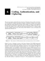
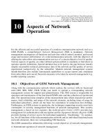
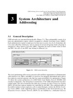
ISDN Reference Model between user plane and control plane. Figure 7.1 shows a
simpli®ed reference model for the GSM User±Network Interface (UNI) Um, where
the layer-transcending management plane is not elaborated in the following. In the
user plane, protocols of the seven OSIlayers are de®ned for the transport of data
from a subscriber or a data terminal. User data is transmitted in GSM across the air
7
Figure 7.1: Logical channels at the air interface in the ISDN reference model
GSM Switching, Services and Protocols: Second Edition. Jo
È
rg Eberspa
È
cher,
Hans-Jo
È
rg Vo
È
gel and Christian Bettstetter
Copyright q 2001 John Wiley & Sons Ltd
Print ISBN 0-471-49903-X Online ISBN 0-470-84174-5
interface over traf®c channels TCH, which therefore belong to Layer 1 of the user plane
(Figure 7.1).
Protocols in the signaling plane are used to handle subscriber access to the network and
for the control of the user plane (reservation, activation, routing, switching of channels
and connections). In addition, signaling protocols between network nodes are needed
(network internal signaling). The Dm channels of the air interface in GSM are signaling
channels and are therefore realized in the signaling plane (Figure 7.1).
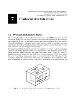
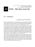
Since signaling channels are physically present but mostly unused during an active user
connection, it is obvious to use them also for the transmission of certain user data. In
ISDN, packet-switched data communication is therefore permitted on the D channel, i.e.
the physical D channel carries multiplexed traf®c of signaling data (s-data) and user
(payload) data (p-data). The same possibility also exists in GSM. Data transmission
without allocation of a dedicated traf®c channel is used for the Short Message Service
(SMS) by using free capacities on signaling channels. For this purpose, a separate
SDCCH is allocated, or, if a traf®c connection exists, the SMS protocol data units are
multiplexed onto the signaling data stream of the SACCH (Figure 7.2).
The control (signaling) and user plane can be de®ned and implemented separately of each
other, ignoring for the moment that control and user data have to be transmitted across the
same physical medium at the air interface and that signaling procedures initiate and control
activities in the user plane. Therefore, for each plane there exists a corresponding separate
protocol architecture within the GSM system: the user data protocol architecture (see
Section 7.2) and the signaling protocol architecture (see Section 7.3), with an additional
separate protocol architecture for the transmission of p-data on the control (signaling) plane
(see Section 7.3.2). A protocol architecture comprises not only the protocol entities at the
radio interface Um but all protocol entities of the GSM network components.
7 Protocol Architecture
126
Figure 7.2: User data and control at the air interface
7.2 Protocol Architecture of the User Plane
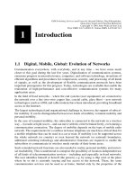
A GSM PLMN can be de®ned by a set of access interfaces (see Section 9.1) and a set
of connection types used to realize the various communication services. A connection
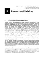
in GSM is de®ned between reference points. Connections are constructed from
connection elements (Figure 7.3), and the signaling and transmission systems may
change from element to element. Two elements therefore exist within a GSM connec-
tion: the radio interface connection element and the A interface connection element.
The radio interface and the pertinent connection element are de®ned between the MS
and the BSS, whereas the A interface connection element exists between BSS and
MSC across the A interface. A GSM-speci®c signaling system is used at the radio
interface, whereas ISDN-compatible signaling and payload transport are used across
the A interface. The BSS is subdivided into BTS and BSC. Between them they de®ne
the Abis interface, which has no connection element de®ned; this is because it is
usually transparent for user data.
A GSM connection type provides a way to describe GSM connections. Connection types
represent the capabilities of the lower layers of the GSM PLMN. In the following section,
the protocol models are presented as the basis for some of the connection types de®ned in
the GSM standards. These are speech connections and transparent as well as nontran-
sparent data connections. A detailed discussion of the individual connection types can be
found in Chapter 9 with a description of how various data services have been realized in
GSM.
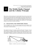
7.2.1 Speech Transmission
The digital, source-coded speech signal of the mobile station is transmitted across the air
interface in error-protected and encrypted form. The signal is then deciphered in the BTS,
and the error protection is removed before the signal is passed on. This specially
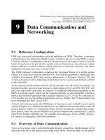
protected speech transmission occurs transparently between mobile station and a Trans-
coding and Rate Adaptation Unit (TRAU) which serves to transform the GSM speech-
coded signals to the ISDN standard format (ITU-T A-law). A possible transport path for
speech signals is shown in Figure 7.4, where the bit transport plane (encryption and
TDMA/FDMA) has been omitted.
A simple GSM speech terminal (MT0, see also Figure 9.1) contains a GSM Speech
Codec (GSC) for speech coding. Its speech signals are transmitted to the BTS after
channel coding (FEC) and encryption, where they are again deciphered, decoded, and
7.2 Protocol Architecture of the User Plane
127
Figure 7.3: Connection elements
if necessary, error-corrected. More than one GSM speech signal can be multiplexed onto
an ISDN channel, with up to four GSM speech signals (at 13 kbit/s each) per ISDN B
channel (64 kbit/s). Before they are passed to the MSC, speech signals are transcoded in
the BSS from GSM format to ISDN format (ITU-T A-law).
The BTSs are connected to the BSC over digital ®xed lines, usually leased lines or
microwave links, with typical transmission rates of 2048 kbit/s (in Europe), 1544 kbit/
s (in the USA) or 64 kbit/s (ITU-T G. 703, G. 705, G. 732). For speech transmission, the
BSS implements channels of 64 or 16 kbit/s. The physical placement of the Transcoding
and Rate Adaptation Unit (TRAU) largely determines which kind of speech channel is
used in the ®xed network. The TRAU performs the conversion of speech data between
GSM format (13 kbit/s) and ISDN A-law format (64 kbit/s). In addition, it is responsible
for the adaptation of data rates, if necessary, for data services. There are two alternatives
for the positioning of the TRAU: the TRAU can be placed into the BTS or outside of the
BTS into the BSC. An advantage of placing the TRAU outside of the BTS is that up to
four speech signals can be submultiplexed (MPX in Figure 7.4) onto an ISDN B channel,
so that less bandwidth is required on the BTS-to-BSC connection. Beyond this consid-
eration, placing the TRAU outside of the BTS allows the TRAU functions to be
combined for all BTSs of a BSS in one separate hardware unit, perhaps produced by a
separate manufacturer. The TRAU is, however, always considered as part of the BSS and
not as an independent network element.
Figure 7.5 shows some variants of TRAU placement. A BTS consists of a Base Control
Function (BCF) for general control functions like frequency hopping, and several (at
least one) Transceiver Function (TRX) modules which realize the eight physical TDMA
channels on each frequency carrier. The TRX modules are also responsible for channel
coding and decoding as well as encryption of speech and data signals. If the TRAU is
integrated into the BTS, speech transcoding between GSM and ISDN formats is also
done within the BTS.
In the ®rst case, TRAU within the BTS (BTS 1,2,3 in Figure 7.5), the speech signal in the
BTS is transcoded into a 64 kbit/s A-law signal, and a single speech signal per B channel
(64 kbit/s) is transmitted to the BSC/MSC. For data signals, the bit rates are adapted to
64 kbit/s, or several data channels are submultiplexed over one ISDN channel. The
resulting user plane protocol architecture for speech transport is shown in Figure 7.6.
7 Protocol Architecture
128
Figure 7.4: Speech transmission in GSM
GSM-coded speech (13 kbit/s) is transmitted over the radio interface (Um) in a format
that is coded for error protection and encryption. At the BTS site, the GSM signal is
transcoded into an ISDN speech signal and transmitted transparently through the ISDN
access network of the MSC.
In the second case, the TRAU resides outside of the BTS (BTS 4 in Figure 7.5) and is
considered a part of the BSC. However, physically it could also be located at the MSC
site, i.e. at the MSC side of the BSC-to-MSC links (Figure 7.7). Channel coding/decod-
ing and encryption are still performed in the TRX module of the BTS, whereas speech
transcoding takes place in the BSC. For control purposes, the TRAU needs to receive
synchronization and decoding information from the BTS, e.g. Bad Frame Indication
(BFI) for error concealment (see Section 6.1). If the TRAU does not reside in the
BTS, it must be remotely controlled from the BTS by inband signaling. For this purpose,
a subchannel of 16 kbit/s is reserved for the GSM speech signal on the BTS-to-BSC link,
7.2 Protocol Architecture of the User Plane
129
Figure 7.5: BTS architecture variations and TRAU placement
Figure 7.6: GSM protocol architecture for speech (TRAU at BTS site) Um
so an additional 3 kbit/s is made available for inband signaling. Alternatively, the GSM
speech signal with added inband signaling could also be transmitted in a full ISDN B
channel.
7.2.2 Transparent Data Transmission
The digital mobile radio channel is subject to severe quality variations and generates
burst errors, which one tries to correct through interleaving and convolutional codes
(see Section 6.2). However, if the signal quality is too low due to fading breaks or
interference, the resulting errors cannot be corrected. For data transmission across the
air interface Um, a residual bit error ratio varying between 10
22
and 10
25
according
to channel conditions can be observed [58]. This kind of variable quality of data
transmission at the air interface determines the service quality of transparent data
transmission. Transparent data transmission de®nes a GSM connection type used for
the realization of some basic bearer services (transparent asynchronous and synchro-
nous data, Table 4.2). The pertinent protocol architecture is illustrated in Figure 7.8.
The main aspect of the transparent connection type is that user data is protected
against transmission errors by forward error correction only across the air interface.
Further transmission within the GSM network to the next MSC with an interworking
function (IWF) to an ISDN or a PSTN occurs unprotected on digital line segments,
which have anyway a very low bit error ratio in comparison to the radio channel. The
transparent GSM data service offers a constant throughput rate and constant trans-
7 Protocol Architecture
130
Figure 7.7: GSM protocol architecture for speech
mission delay; however, the residual error ratio varies with channel quality due to the
limited correction capabilities of the FEC.
For example, take a data terminal communicating over a serial interface of type V.24. A
transparent bearer service provides access to the GSM network directly at a mobile
station or through a terminal adapter (reference point R in Figure 9.1). A data rate of
up to 9600 bit/s can be offered based on the transmission capacity of the air interface and
using an appropriate bit rate adaptation. The bit rate adaptation also performs the
required asynchronous-to-synchronous conversion at the same time. This involves
supplementing the tokens arriving asynchronously from the serial interface with ®ll
data, since the channel coder requires a ®xed block rate. This way there is a digital
synchronous circuit-switched connection between the terminal accessing the service and
the IWF in the MSC, which extends across the air interface and the digital ISDN B
channel inside the GSM network; this synchronous connection is completely transparent
for the asynchronous user data of the terminal equipment (TE).
7.2.3 Nontransparent Data Transmission
Compared to the bit error ratio of the ®xed network, which is on the order of 10
26
to
10
29
, the quality of transparent data service is often insuf®cient for many applications,
especially under adverse conditions. To provide more protection against transmission
errors, more redundancy has to be added to the data stream. Since this redundancy is not
always required, but only when there are residual errors in the data stream, forward error
correction is inappropriate. Rather, an error detection scheme with automatic retransmis-
sion of faulty blocks is used, Automatic Repeat Request (ARQ). Such an ARQ scheme
which was speci®cally adapted to the GSM channel, is the Radio Link Protocol (RLP).
The assumption for RLP is that the underlying forward error correction of the convolu-
tional code realizes a channel with an average block error ratio of less than 10%, with a
block corresponding to an RLP protocol frame of length 240 bits. Now the nontranspar-
ent channel experiences a constantly lower bit error ratio than the transparent channel,
independent of the varying transmission quality of the radio channel; however, due to the
7.2 Protocol Architecture of the User Plane
131
Figure 7.8: GSM protocol architecture for transparent data
RLP-ARQ procedure both throughput and transmission delay vary with the radio channel
quality.
The data transmission between mobile station and interworking function of the next MSC
is protected with the data link layer protocol RLP, i.e. the endpoints of RLP terminate in
MS and IWF entities, respectively (Figure 7.9). At the interface to the data terminal TE, a
Nontransparent Protocol (NTP) and an Interface Protocol (IFP) are de®ned, depending
on the nature of the data terminal interface. Typically, a V.24 interface is used to carry
character-oriented user data. These characters of the NTP are buffered and combined into
blocks in the Layer 2 Relay (L2R) protocol, which transmits them as RLP frames. The
data transport to and from the data terminal is ¯ow-controlled. Therefore, transmission
within the PLMN is no longer transparent for the data terminal. At the air interface, a
new RLP frame is transmitted every 20 ms; thus L2R may have to insert ®ll tokens, if a
frame cannot be completely ®lled at transmission time.
The RLP protocol is very similar to the HDLC of ISDN with regard to frame structure
and protocol procedures, the main difference being the ®xed frame length of 240 bits, in
contrast to the variable length of HDLC. The frame consists of a 16-bit protocol header,
200-bit information ®eld, and a 24-bit Frame Check Sequence (FCS); see Figure 7.10.
Because of the ®xed frame length, the RLP has no reserved ¯ag pattern, and a special
procedure to realize code transparency like bit stuf®ng in HDLC is not needed. The very
short ± and hence less error prone ± frames are exactly aligned with channel coding
blocks. (The probability of frame errors increases with the length of the frame.)
RLP makes use of the services of the lower layers to transport its protocol data units
(PDUs). The channel offered to RLP therefore has the main characteristic of a 200 ms
transmission delay, besides the possibly occurring residual bit errors. The delay is mostly
caused by interleaving and channel coding, since the transmission itself takes only about
25 ms for a data rate of 9600 bit/s. This means it will take at least 400 ms until a positive
7 Protocol Architecture
132
Figure 7.9: GSM protocol architecture for nontransparent data
acknowledgement is received for an RLP frame, and protocol parameters like transmis-
sion window and repeat timers need to be adjusted accordingly.
The RLP header is similar to the one used in HDLC [31], with the difference that the
RLP header contains no address information but only control information for which 16
bits are available. One distinguishes between supervisory frames and information frames.
Whereas information frames carry user data, supervisory frames serve to control the
connection (initialize, disconnect, reset) as well as the retransmission of information
frames during data transfer. The information frames are labeled with a sequence number
N(S) for identi®cation, for which 6 bits are available in the RLP header (Figure 7.10). To
conserve space, this ®eld is also used to code the frame type. Sequence number values
smaller than 62 indicate that the frame carries user data in the information ®eld (infor-
mation frame). Otherwise the information ®eld is discarded, and only the control infor-
mation in the header is of interest (supervisory frame). These frames are marked with the
reserved values 62 and 63 (Figure 7.10).
Due to this header format, information frames can also carry (implicit) control informa-
tion, a process known as piggybacking. The header information of the second variant can
be carried completely within the header of an information frame. This illustrates further
how RLP has been adapted to the radio channel, since it makes the transmission of
additional control frames unnecessary during information transfer, which reduces the
protocol overhead and increases the throughput.
Thus the send sequence number is calculated modulo 62, which amounts to a window of
61 frames, allowing 61 outstanding frames without acknowledgement before the sender
has to receive the acknowledgement of the ®rst frame. Positive acknowledgement is
used; i.e. the receiver sends an explicit supervisory frame as a receipt or an implicit
receipt within an information frame. Such an acknowledgement frame contains a receive
frame number N(R) which designates correct reception of all frames, including send
sequence number N(S) N(R) 2 1.
Each time the last information frame is sent, a timer T1 is started at the sender. If an
acknowledgement for some or all sent frames is not received in time, perhaps because the
acknowledging RLP frame had errors and was therefore discarded, the timer expires and
causes the sender to request an explicit acknowledgement. Such a request may be
7.2 Protocol Architecture of the User Plane
133
Figure 7.10: Frame structure of the RLP protocol
repeated N2 times; if this still leads to no acknowledgement, the connection is termi-
nated. If an acknowledgement N(R) is obtained after expiration of timer T1, all sent
frames starting from and including N(R) are retransmitted. In the case of an explicitly
requested acknowledgement, this corresponds to a modi®ed Go-back-N procedure. Such
a retransmission is also allowed only up to N2 times. If no receipt can be obtained even
after N2 trials, the RLP connection is reset or terminated.
Two procedures are provided in RLP for dealing with faulty frames: selective reject, which
selects a single information frame without acknowledgement; and reject, which causes
retransmission with implicit acknowledgement. With selective reject, the receiving RLP
entity requests retransmission of a faulty frame with sequence number N(R), but this does
not acknowledge receipt of other frames. Each RLP implementation must at least include
the reject method for requesting retransmission of faulty frames. With a reject, the receiver
asks for retransmission of all frames starting with the ®rst defective received frame with
number N(R) (Go-back-N). Simultaneously, this implicitly acknowledges correct recep-
tion of all frames up to and including N(R) 2 1. Realization of selective reject is not
mandatory in RLP implementations, but it is recommended. The reason is that Go-back-N
causes retransmission of frames that may have been transmitted correctly and thus dete-
riorates the throughput that could be achieved with selective reject.
7.3 Protocol Architecture of the Signaling Plane
7.3.1 Overview of the Signaling Architecture
Figure 7.11 shows the essential protocol entities of the GSM signaling architecture
(control plane or signaling plane). Three connection elements are distinguished: the
radio-interface connection element, the BSS-interface connection element, and the A-
interface connection element. This control plane protocol architecture consists of a GSM-
speci®c part with the interfaces Um and Abis and a part based on Signaling System
Number 7 (SS#7) with the interfaces A, B, C, E (Figure 7.11). This change of signaling
system corresponds to the change from radio interface connection element to A-interface
connection element as discussed above for the user data plane (Figure 7.3).
The radio interface Um is de®ned between MS and BSS, more exactly between MS and
BTS. Within the BSS, the BTS and the BSC cooperate over the Abis interface, whereas the
A interface is located between BSC and MSC. The MSC has also signaling interfaces to
VLR (B), HLR (C), to other MSCs (E), and to the EIR (F). Further signaling interfaces are
de®ned between VLRs (G) and between VLR and HLR (D). Figure 3.9 gives an overview
of the interfaces in a GSM PLMN.
Physical Layer ± In the control plane, the lowest layer of the protocol model at the air
interface, the Physical Layer, implements the logical signaling channels (TDMA/
FDMA, multiframes, channel coding, etc.; see Chapter 5, Sections 6.1, 6.2, and 6.3).
Like user data, signaling messages are transported over the Abis interface (BTS-BSC)
and the A interface (BSC-MSC) on digital lines with data rates of 2048 kbit/s
(1544 kbit/s in the USA), or 64 kbit/s (ITU-T G.703, G.705, G.732).
Layer 2: LAPDm ± On Layer 2 of the logical signaling channels across the air interface,
7 Protocol Architecture
134
7.3 Protocol Architecture of the Signaling Plane
135
Figure 7.11: GSM protocol architecture for signaling
a data link protocol entity is implemented, the Link Access Procedure on Dm channels
(LAPDm). LAPDm is a derivative of LAPD which is speci®cally adapted to the air
interface. This data link protocol is responsible for the protected transfer of signaling
messages between MS and BTS over the air interface, i.e. LAPDm is terminated in
mobile station and base station.
In essence, LAPDm is a protocol similar to HDLC which offers a number of services on
the various logical Dm channels of Layer 3: connection setup and teardown, protected
signaling data transfer. It is based on various link protocols used in ®xed networks, such
as LAPD in ISDN [7]. The main task of LAPDm is the transparent transport of messages
between protocol entities of Layer 3 with special support for:
² Multiple entities in Layer 3 and Layer 2
² Signaling for broadcasting (BCCH)
² Signaling for paging (PCH)
² Signaling for channel assignment (AGCH)
² Signaling on dedicated channels (SDCCH)
A detailed discussion of LAPDm is presented in Section 7.4.2.
Layer 3 ± In the mobile station, the LAPDm services are used at Layer 3 of the signaling
7 Protocol Architecture
136
Figure 7.12: Layer 3 protocol architecture at the MS side
protocol architecture. There, Layer 3 is divided into three sublayers: Radio Resource
Management (RR), Mobility Management (MM), and Connection Management (CM).
The protocol architecture formed by these three sublayers is shown in Figure 7.12.
Connection management is further subdivided into three protocol entities: Call Control
(CC), Supplementary Services (SS), and Short Message Service (SMS). Additional multi-
plexing functions within Layer 3 are required between these sublayers.
The call-independent supplementary services and the short message service are offered to
higher layers at two Service Access Points (SAPs), MNSS and MNSMS. A more detailed
look at the services offered by the RR, MM, and CC protocol entities is given in the
following.
Radio Resource Management ± Radio Resource Management (RR) essentially handles
the administration of the frequencies and channels. This involves the RR module of the
MS communicating with the RR module of the BSC (Figure 7.11). The general objective
of the RR is to set up, maintain, and take down RR connections which enable point-to-
point communication between MS and network. This also includes cell selection in idle
mode and handover procedures. Furthermore, the RR is responsible for monitoring
BCCH and CCCH on the downlink when no RR connections are active.
The following functions are realized in the RR module:
² Monitoring of BCCH and PCH (readout of system information and paging messages)
² RACH administration: mobile stations send their requests for connections and replies to
paging announcements to the BSS
² Requests for and assignments of data and signaling channels
² Periodic measurement of channel quality (quality monitoring)
² Transmitter power control and synchronization of the MS
² Handover (part of which is sometimes erroneously attributed to roaming functions and
mobility management), always initiated by the network
² Synchronization of encryption and decryption on the data channel
The RR sublayer provides several services at the RR-SAP to the MM sublayer. These
services are needed to set up and take down signaling connections and to transmit
signaling messages.
Mobility Management ± Mobility Management (MM) encompasses all the tasks result-
ing from mobility. The MM activities are exclusively performed in cooperation between
MS and MSC, and they include
² TMSIassignment
² Localization of the MS
² Location updating of the MS; parts of this are sometimes known as roaming functions
² Identi®cation of the MS (IMSI, IMEI)
² Authentication of the MS
² IMSI attach and detach procedures (e.g. at insertion or removal of SIM)
² Ensuring con®dentiality of subscriber identity
Registration services for higher layers are provided by Layer 3 at the MMREG-SAP
(Figure 7.12). Registration involves the IMSI attach and detach procedures which are
7.3 Protocol Architecture of the Signaling Plane
137
used by the mobile to report state changes such as power-up or power-down, or SIM card
removal or insertion.
The MM sublayer offers its services at the MMCC-SAP, MMSS-SAP, and MMSMS-
SAP to the CC, SS, and SMS entities. This is essentially a connection to the network side
over which these units can communicate.
Connection Management ± Connection Management consists of three entities: Call
Control (CC), Supplementary Services (SS), and Short Message Service (SMS). Call
control handles all tasks related to setting up, maintaining and taking down calls. The
services of call control are provided at the MNCC-SAP, and they encompass:
² Establishment of normal calls (MS-originating and MS-terminating)
² Establishment of emergency calls (only MS-originating)
² Termination of calls
² Dual-Tone Multifrequency (DTMF) signaling
² Call-related supplementary services
² Incall modi®cation: the service may be changed during a connection (e.g. speech and
transparent/nontransparent data are alternating; or speech and fax alternate)
The service primitives at this SAP of the interface to higher layers report reception of
incoming messages and effect the sending of messages, essentially ISDN user-network
signaling according to Q.931.
RR messages are mainly exchanged between MS and BSS. In contrast, CM and MM
functions are handled exclusively between MS and MSC; the exact division of labor
between BTS, BSC, and MSC is summarized in Table 7.1. As can be seen, RR messages
have to be transported over the Um and Abis interfaces, whereas CM and MM messages
need additional transport mechanisms across the A interface.
Message Transfer Part ± From a conceptual viewpoint, the A interface in GSM
networks is the interface between the MSCs, the ISDN exchanges with mobile network
speci®c extensions, and the BSC, the dedicated mobile network speci®c control units.
Here too is the reference point, where the signaling system changes from GSM-speci®c
to the general ISDN-compatible SS#7. Message transport in the SS#7 network is realized
through the Message Transfer Part (MTP). In essence, MTP comprises the lower three
layers of the OSIReference Model, i.e. the MTP provides routing and transport of
signaling messages.
A slightly modi®ed (reduced) version of the MTP, called MTP
0
, has been de®ned for the
protected transport of signaling messages across the A interface between BSC and MSC. At
the ISDN side of the MSCs, the complete MTP is available. For signaling transactions
between MSC and MS (CM, MM), it is necessary to establish and identify distinct logical
connections. The Signaling Connection Control Part (SCCP) is used for this purpose to
facilitate implementation with a slightly reduced range of functions de®ned in SS#7.
BSS Application Part ± For GSM-speci®c signaling between MSC and BSC, the Base
Station System Application Part (BSSAP) has been de®ned. The BSSAP consists of the
Direct Transfer Application Part (DTAP) and the Base Station System Management
Application Part (BSSMAP). The DTAP is used to transport messages between MSC
and MS. These are the Call Control (CC) and Mobility Management (MM) messages. At
7 Protocol Architecture
138
the A interface, they are transmitted with DTAP and then passed transparently through
the BSS across the Abis interface to the MS without interpretation by the BTS.
7.3 Protocol Architecture of the Signaling Plane
139
Table 7.1: Distribution of functions between BTS, BSC, and MSC (according to GSM Rec. 08.02, 08.52)
BTS BSC MSC
Terrestrial channel management
MSC-BSC-channels
Channel allocation X
Blocking indication X
BSC-BTS-Channels
Channel allocation X
Blocking indication X
Mobility management
Authentication X
Location updating X
Call control X
Radio channel management
Channel coding/decoding X
Transcoding/rate adaptation X
Interworking function X
Measurements
Uplink measuring X X
Processing of reports from MS/TRX X X X
Traf®c measurements X
Handover
BSC internal, intracell X
BSC internal, intercell X
BSC external X
Recognition, decision, execution X
HO access detection X
Paging
Initiation X
Execution X
Channel con®guration management X
Frequency hopping
Management X
The BSSMAP is the protocol de®nition part which is responsible for all of the
administration and control of the radio resources of the BSS. RR is one of the
main functions of a BSS. Therefore, the RR entities terminate in the mobile station
and the BTS or BSC respectively. Some functions of RR however, require involve-
ment of the MSC (e.g. some handover situations, or release of connections or chan-
nels). Such actions should be initiated and controlled by the MSC (e.g. handover and
channel assignment). This control is the responsibility of BSSMAP. RR messages are
mapped and converted within the BSC into procedures and messages of BSSMAP and
7 Protocol Architecture
140
Table 7.1 (continued)
BTS BSC MSC
Execution X
TCH management
Channel allocation X
Link supervision X
Channel release X X
Idle channel observation X
Power control determination X X
SDCCH management
SDCCH allocation X
Link supervision X
Channel release X X
Power control determination X X
BCCH/CCCH management
Message scheduling management X
Message scheduling execution X
Random access detection X
Immediate assign X
Timing Advance
Calculation X
Signaling to MS at random access X
Signaling to MS at handover/during call X
Radio resource indication
Report status of idle channels X
LAPDm functions X
Encryption
Management X
Execution X
vice versa. BSSMAP offers the functions which are required at the A interface
between BSS and MSC for RR of the BSS. Accordingly, RR messages initiate
BSSMAP functions, and BSSMAP functions control RR protocol functions.
BTS Management ± A similar situation exists at the Abis interface. Most of the RR
messages are passed transparently by the BTS between MS and BSC. Certain RR infor-
mation, however, must be interpreted by the BTS, e.g. in situations like random access of
the MS, the start of the ciphering process, or paging to localize an MS for connection
setup. The Base Transceiver Station Management (BTSM) contains functions for the
treatment of these messages and other procedures for BTS management. Besides, a
mapping occurs in the BTS from BTSM onto the RR messages relevant at the air inter-
face (RR
0
, Figure 7.11).
Mobile Application Part ± The MSC is equipped with the Mobile Application Part
(MAP), a mobile network speci®c extension of SS#7, for communication with the other
components of the GSM network (the HLR and VLR registers, other MSCs) and other
PLMNs. Among the MAP functions are all signaling functions among MSCs as well as
between MSC and the registers (Figure 7.13). These functions include
² Updating of residence information in the VLR
² Cancellation of residence information in the VLR
² Storage of routing information in the HLR
² Updating and supplementing of user pro®les in HLR and VLR
² Inquiry of routing information from the HLR
² Handover of connections between MSC
The exchange of MAP messages, e.g. with other MSCs, HLR, or VLR, occurs over the
transport and transaction protocol of the SS#7. The SS#7 transaction protocol is the
7.3 Protocol Architecture of the Signaling Plane
141
Figure 7.13: Protocol interfaces in the mobile network
Transaction Capabilities Application Part (TCAP). A connectionless transport service is
offered by the Signaling Connection Control Part (SCCP).
The MAP functions require channels for signaling between different PLMNs which are
provided by the international SS#7. Access to SS#7 occurs through the ®xed ISDN.
Connection to the ®xed network is typically done through leased lines; in the case of the
German GSM network operators, it is through lines with a rate of 2 Mbit/s from Deutsche
Telekom [25]. Often the majority of the MSC in a PLMN has such an access to the ®xed
network. On these lines, both user data and signaling data is transported. From the
viewpoint of a ®xed network, an MSC is integrated into the network like a normal
ISDN exchange node. Outside of a PLMN, starting with the GMSC, calls for mobile
stations are treated like calls for subscribers of the ®xed network, i.e. the mobility of a
subscriber with an MSISDN becomes ``visible'' only beyond the GMSC. For CC, the
MSC has the same interface as an ISDN switching node. Connection-oriented signaling
of GSM networks is mapped at the ®xed network side (interface to ISDN) into the ISDN
User Part (ISUP) used to connect ISDN channels through the network (Figure 7.14). The
mobile-speci®c signaling of the MAP is routed over a gateway of the PLMN (GMSC)
and the International Switching Center (ISC) of the national ISDN network into the
international SS#7 network [25]. In this way, transport of signaling data between differ-
ent GSM networks is also guaranteed without problems.
7.3.2 Transport of User Data in the Signaling Plane
In the signaling plane (control plane) of the GSM architecture, one can also transport
packet-oriented user data from or to mobile stations. This occurs for the point-to-point
7 Protocol Architecture
142
Figure 7.14: International signaling relations via ISDN [25]
SMS (see Section 4.2). Short messages are always transmitted in store-and-forward mode
through a Short Message Service Center (SMS-SC). The service center accepts these
messages, which can be up to 160 characters long, and forwards them to the recipients
(other mobile stations or fax, email, etc.). In principle, GSM de®nes a separate protocol
architecture for the realization of this service.
Between mobile station and service center, short messages are transmitted using a
connectionless transport protocol: Short Message Transport Protocol (SM-TP) which
uses the services of the signaling protocols within the GSM network. Transport of
these messages outside of the GSM network is not de®ned. For example, the SMS-SC
could be directly connected to the gateway switching center (SMS-GMSC), or it could be
connected to a Short Message Service Interworking MSC (SMS-IWMSC) through an
X.25 connection (Figure 7.15). Within the GSM network between MSCs, a short
message is transferred with the MAP and the lower layers of SS#7. Finally, between a
mobile station and its local MSC, two protocol layers are responsible for the transfer of
transport protocol units of SMS. First, there is the SMS entity in the CM sublayer of
Layer 3 at the user-network interface (see Figure 7.12) which realizes the Short Message
Control Protocol (SM-CP) and its connection-oriented service. Second, there is the relay
layer, in which the Short Message Relay Protocol (SM-RP) is de®ned, which offers a
connectionless service for transfer of SMS transport PDUs between MS and MSC. This,
however, uses services at the service access point MMSMS-SAP (see Figure 7.12) and
thus a connection of the MM sublayer.
In addition to the SM-CP, the relay protocol SM-RP was introduced above the CM
sublayer (Figures 7.12 and 7.15) to realize an acknowledged transmission of short
messages, but with minimal overhead for the radio channel. A short message sent by
a mobile station is passed over the signaling network until it reaches the service center
SMS-SC. If the service center determines the error-free reception of a message, an
acknowledgement message is returned on the reverse path, which ®nally causes sending
of an acknowledgement message from the SM-RP entity in the MSC to the mobile
station. Until this acknowledgement message arrives, the connection in the MM sublayer
7.3 Protocol Architecture of the Signaling Plane
143
Figure 7.15: Protocol architecture for SMS transfer
can be taken down, and thus also the reserved radio channel. In this way, radio resources
across the air interface are only occupied during the actual transmission of SM-RP
messages. And each successful transmission of an SM-CP PDU across the MM connec-
tion, which includes the error-prone air interface, is immediately acknowledged, or else
errors are immediately reported to the sending SM-CP entity. So if a message is damaged
at the radio interface, this avoids it being transmitted to the service center.
7.4 Signaling at the Air Interface (Um)
Signaling at the user±network interface in GSM is essentially concentrated in Layer 3.
Layers 1 and 2 provide the mechanisms for the protected transmission of signaling
messages across the air interface. Besides the local interface, they contain functionality
and procedures for the interface to the BTS.
The signaling of Layer 3 at the user±network interface is very complex and comprises
protocol entities in the mobile station and in all functional entities of the GSM network
(BTS, BSC, and MSC).
7.4.1 Layer 1 of the MS-BTS Interface
Layer 1 of the OSIReference Model (physical layer) contains all the functions necessary
for the transmission of bit streams over the physical medium, in this case the radio
channel. GSM Layer 1 de®nes a series of logical channels based on the channel access
7 Protocol Architecture
144
Figure 7.16: Layer 1 service interfaces
procedures with their physical channels. The higher layer protocols access these services
at the Layer 1 service interface. The three interfaces of Layer 1 are schematically
illustrated in Figure 7.16.
LAPDm protocol frames are transmitted across the service mechanisms of the data link
layer interface, and the establishment of logical channels is reported to Layer 2. The
communication across this interface is de®ned by abstract physical layer service primi-
tives. A separate Service Access Point (SAP) is de®ned for each logical control channel
(BCCH, PCH 1 AGCH, RACH, SDCCH, SACCH, FACCH).
Between Layer 1 and the RR sublayer of Layer 3 there is a direct interface. The abstract
service primitives exchanged at this interface mostly concern channel assignment and
Layer 1 system information, including measurement results of channel monitoring. At the
third Layer 1 interface, the traf®c channels for user (payload) data are provided.
The service access points (SAP) of Layer 1 as de®ned in GSM are not genuine service
access points in the spirit of OSI. They differ from the PHY-SAPs of the OSI Reference
Model insofar as these SAPs are controlled by Layer 3 RR sublayer (layer management,
establishment and release of channels) rather than by control procedures in the link layer.
Control of Layer 1 SAPs by RR comprises activation and deactivation, con®guration,
routing and disconnection of physical and logical channels. Furthermore, exchange of
measurement and control information for channel monitoring occurs through service
primitives.
7.4.1.1 Layer 1 Services
Layer 1 services of the GSM user±network interface are divided into three groups:
² Access capabilities
² Error detection
² Encryption
Layer 1 provides a bit transport service for the logical channels. These are transmitted in
multiplexed format over physical channels which consist of elements de®ned for the
transmission on the radio channel (frequency, time slot, hopping sequence, etc.; see
Section 7.1). Some physical channels are provided for common (shared) use (BCCH
and CCCH), whereas others are assigned to dedicated connections with single mobile
stations (dedicated physical channels). The combination of logical channels used on a
physical channel can vary over time, e.g. TCH 1 SACCH/FACCH replaced by
SDCCH 1 SACCH (see Table 5.4).
The GSM standard distinguishes explicitly between access capabilities for dedicated
physical channels and for common physical channels BCCH/CCCHs. Dedicated physical
channels are established and controlled by Layer 3 RR management. During the opera-
tion of a dedicated physical channel, Layer 1 continuously measures the signal quality of
the used channel and the quality of the BCCH channels of the neighboring base stations.
This measurement information is passed to Layer 3 in measurement service primitives
MPH. In idle mode, Layer 1 selects the cell with the best signal quality in cooperation
with the RR sublayer based on the quality of the BCCH/CCCH (cell selection).
7.4 Signaling at the Air Interface (Um)
145
GSM Layer 1 offers an error-protected bit transport service and therefore also error
detection and correction mechanisms. To do this, error-correcting and error-detecting
coding mechanisms are provided (see Section 6.2). Frames recognized as faulty are not
passed up to Layer 2. Furthermore, security-relevant functions like encryption of user
data is implemented in Layer 1 (see Section 6.3).
7.4.1.2 Layer 1: Procedures and Peer-to-Peer Signaling
GSM de®nes and distinguishes between two operational modes of a mobile station: idle
mode and dedicated mode (Figure 7.17). In idle mode, the mobile station is either
powered off (state NULL) or it searches for or measures the BCCH with the best signal
quality (state SEARCHING BCH), or is synchronized to a speci®c base station's BCCH
and ready to perform a random access procedure on the RACH for requesting a dedicated
channel in state BCH (see Section 5.5.4).
In state TUNING DCH of the dedicated mode, the mobile station occupies a physical
channel and tries to synchronize with it, which will eventually result in transition to state
7 Protocol Architecture
146
Figure 7.17: State diagram of a mobile station's physical layer
Figure 7.18: Format of an SACCH block
DCH. In this state, the MS is ®nally ready to establish logical channels and switch them
through. The state transitions of Layer 1 are controlled by MPH service primitives of the
RR interface, i.e. directly from the Layer 3 RR sublayer of the signaling protocol stack.
Layer 1 de®nes its own frame structure for the transport of signaling messages, which
occur as LAPDm frames at the SAP of the respective logical channel. Figure 7.18 shows
the format of an SACCH block as an example, which essentially contains 21 octets of
LAPDm data.
Furthermore, the SACCH frame contains a kind of protocol header which carries the
current power level and the value of the timing advance. This header is omitted in the
other logical channels (FACCH, SDCCH, CCCH, BCCH) which contain only LAPDm
PDUs.
7.4.2 Layer 2 Signaling
The LAPDm protocol is the data link protocol for signaling channels at the air interface.
It is similar to HDLC. It provides two operational modes:
² Unacknowledged operation
² Acknowledged operation
In the unacknowledged operation mode, data is transmitted in UIframes (unnumbered
information) without acknowledgement; there is no ¯ow control or L2 error correction.
This operational mode is allowed for all signaling channels, except for the RACH which
is accessed in multiple access mode without reservation or protection.
The acknowledged operation mode provides protected data service. Data is transmitted in
Iframes (information) with positive acknowledgement. Error protection through retrans-
mission (ARQ) and ¯ow control are speci®ed and activated in this mode. This mode is
only used on DCCH channels.
In LAPDm, the Connection End Points (CEPs) of L2 connections are labeled with Data
Link Connection Identi®ers (DLCIs), which consist of two elements:
² The Layer 2 Service Access Point Identi®er (SAPI) is transmitted in the header of the L2
protocol frame.
² The physical channel identi®er on which the L2 connection is or will be established, is
the real Layer 2 Connection End Point Identi®er (CEPI). The CEPI is locally adminis-
tered and not communicated to the L2 peer entity. (The terminology of the GSM
standard is somewhat inconsistent in this case ± what is really meant is the respective
logical channel. The physical channels from the viewpoint of LAPDm are the logical
channels of GSM, rather than the physical channels de®ned by frequency/time slot/
hopping sequence.)
When a Layer 3 message is transmitted, the sending entity chooses the appropriate SAP
and CEP. When the service data unit SDU is handed over at the SAP, the chosen CEP is
given to the L2 entity. Conversely, when receiving an L2 frame, the appropriate L2-CEPI
can be determined from the physical/logical channel identity and the SAPIin the frame
header.
7.4 Signaling at the Air Interface (Um)
147
Speci®c SAPIvalues are reserved for the certain functions:
² SAPI 0 for signaling (CM, MM, RR)
² SAPI 3 for SMS
In the control plane, these two SAPI values serve to separate signaling messages from
packet-oriented user data (short messages). Further functions needing a new SAPIvalue
can be de®ned in future versions of the GSM standard.
An LAPDm entity is established for each of the pertinent physical/logical channels. For
some of the channel/SAPIcombinations only a subset of the LAPDm protocol is needed
(e.g. unacknowledged operation), and some channel/SAPIcombinations are not
supported (Table 7.2). These LAPDm entities perform the Data Link procedure, i.e.
the functions of the L2 peer-to-peer communication as well as the service primitives
between adjacent layers. Segmentation and reassembly of Layer 3 messages is also
included.
7 Protocol Architecture
148
Table 7.2: Logical channels, operational modes and Layer 2 SAPIs
Logical channel SAPI 0 SAPI 3
BCCH Unacknowledged ±
CCCH Unacknowledged ±
SDCCH Unacknowledged
and acknowledged
Unacknowledged
and acknowledged
SACCH assoc. with SDCCH Unacknowledged ±
SACCH assoc. with TCH Unacknowledged Unacknowledged
and acknowledged
FACCH Unacknowledged
and acknowledged
±
Figure 7.19: Sample con®guration of the MS data link layer
Further Layer 2 procedures are the Distribution Procedure and the Random Access (RA)
procedure. The distribution procedure is needed if multiple SAPs are associated with one
physical/logical channel. It performs the distribution of the L2 frames received on one
channel to the respective data link procedure, or the priority-controlled multiplexing of
L2 frames from multiple SAPs onto one channel. The random access procedure is used
on the random access channel (RACH); it deals with the random controlled retransmis-
sion of random access bursts, but it does not perform any error protection on the unidir-
ectional RACH.
For certain aspects of RR, the protocol logic of Layer 3 has to have direct access to the
services of Layer 1. Especially, this is needed for functions of Radio Subsystem Link
Control, i.e. for channel measurement, transmitter power control, and timing advance.
A possible link layer con®guration of an MS is shown in Figure 7.19. The base station
has a similar con®guration with one PCH 1 AGCH, SDCCH and SACCH/FACCH for
each active mobile station.
Figure 7.20 shows the different types of protocol data frames used for communication
between L2 peer entities in MS and BTS. Frame formats A and B are used on the
7.4 Signaling at the Air Interface (Um)
149
Figure 7.20: LAPDm frame formats