Xử lý hình ảnh thông minh P3
Bạn đang xem bản rút gọn của tài liệu. Xem và tải ngay bản đầy đủ của tài liệu tại đây (462.16 KB, 39 trang )
Intelligent Image Processing.SteveMann
Copyright 2002 John Wiley & Sons, Inc.
ISBNs: 0-471-40637-6 (Hardback); 0-471-22163-5 (Electronic)
3
THE EYETAP PRINCIPLE:
EFFECTIVELY LOCATING THE
CAMERA INSIDE THE EYE
AS AN ALTERNATIVE TO
WEARABLE CAMERA SYSTEMS
This chapter discloses the operational principles of the EyeTap reality mediator,
both in its idealized form and as practical embodiments of the invention. The inner
workings of the reality mediator, in particular, its optical arrangement, are described.
3.1 A PERSONAL IMAGING SYSTEM FOR
LIFELONG VIDEO CAPTURE
A device that measures and resynthesizes light that would otherwise pass through
the lens of an eye of a user is described. The device diverts at least a portion of
eyeward-bound light into a measurement system that measures how much light
would have entered the eye in the absence of the device. In one embodiment, the
device uses a focus control to reconstruct light in a depth plane that moves to
follow subject matter of interest. In another embodiment, the device reconstructs
light in a wide range of depth planes, in some cases having infinite or near-
infinite depth of field. The device has at least one mode of operation in which
it reconstructs these rays of light, under the control of a portable computational
system. Additionally the device has other modes of operation in which it can,
by program control, cause the user to experience an altered visual perception of
reality. The device is useful as a visual communications system, for electronic
newsgathering, or to assist the visually challenged.
3.2 THE EYETAP PRINCIPLE
The EyeTap reality mediator is characterized by three components:a lightspace anal-
ysis system; a lightspace modification system; and a lightspace synthesis system.
64
THE EYETAP PRINCIPLE
65
To understand how the reality mediator works, consider the first of these
three components, namely the device called a “lightspace analyzer” (Fig. 3.1).
The lightspace analyzer absorbs and quantifies incoming light. Typically (but not
necessarily) it is completely opaque. It provides a numerical description (e.g., it
turns light into numbers). It is not necessarily flat (e.g., it is drawn as curved to
emphasize this point).
The second component, the lightspace modifier, is typically a processor
(WearComp, etc.) and will be described later, in relation to the first and third
components.
The third component is the “lightspace synthesizer” (Fig. 3.2). The lightspace
synthesizer turns an input (stream of numbers) into the corresponding rays of
light.
Now suppose that we connect the output of the lightspace analyzer to the
input of the lightspace synthesizer (Fig. 3.3). What we now have is an illusory
transparency.
Numerical
description
Incoming
rays of
light
10011000...
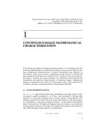
Figure 3.1 Lightspace analyzer absorbs and quantifies every ray of incoming light. It converts
every incoming ray of light into a numerical description. Here the lightspace analyzer is depicted
as a piece of glass. Typically (although not necessarily) it is completely opaque.
Outgoing
synthetic
(virtual)
light
Numerical
description
10011000...
Figure 3.2 The lightspace synthesizer produces rays of light in response to a numerical input.
An incoming numerical description provides information pertaining to each ray of outgoing light
that the device produces. Here the lightspace synthesizer is also depicted as a special piece
of glass.
66
THE EYETAP PRINCIPLE: EFFECTIVELY LOCATING THE CAMERA
Lightspace
analysis
Lightspace
synthesis
Incoming
real light
Outgoing
synthetic
(virtual)
light
10011000...10011000...
Figure 3.3 Illusory transparency formed by connecting the output of the lightspace analysis
glass to the input of the lightspace synthesis glass.
Incoming
(analysis)
Outgoing
(synthesis)
10011000... 10011000...
Figure 3.4 Collinear illusory transparency formed by bringing together the analysis glass and
the synthesis glass to which it is connected.
Moreover suppose that we could bring the lightspace analyzer glass into direct
contact with the lightspace synthesizer glass. Placing the two back-to-back would
create a collinear illusory transparency in which any emergent ray of virtual
light would be collinear with the incoming ray of real light that gave rise to it
(Fig. 3.4).
Now a natural question to ask is: Why make all this effort in a simple illusion
of transparency, when we can just as easily purchase a small piece of clear
glass?
The answer is the second component, the lightspace modifier, which gives us
the ability to modify our perception of visual reality. This ability is typically
achieved by inserting a WearComp between the lightspace analyzer and the
lightspace synthesizer (Fig. 3.5). The result is a computational means of altering
the visual perception of reality.
PRACTICAL EMBODIMENTS OF EYETAP
67
Incoming
(analysis)
Outgoing
(synthesis)
WearComp
Figure 3.5 Reality mediator satisfying the collinearity (EyeTap) condition.
In summary:
1. A lightspace analyzer converts incoming light into numbers.
2. A lightspace modifier (i.e., a processor that is typically body-worn) alters
the lightspace by processing these numbers.
3. A lightspace synthesizer converts these numbers back into light.
3.2.1 ‘‘Lightspace Glasses’’
A visor made from the lightspace analysis glass and lightspace synthesis glass
could clearly be used as a virtual reality (VR) display because of the synthesis
capability. It could absorb and quantify all the incoming rays of light and then
simply ignore this information, while the synthesis portion of the glass could
create a virtual environment for the user. (See Fig. 3.6, top panel.)
Now, in addition to creating the illusion of allowing light to pass right through,
the visor also can create new rays of light, having nothing to do with the rays
of light coming into it. The combined illusion of transparency and the new light
provides the wearer with an AR experience (Fig. 3.6, middle panel). Finally,
the glasses could be used to alter the perception of visual reality, as described
previously in this chapter and the previous chapter (Fig. 3.6, bottom panel). Thus
VR is a special case of AR which is a special case of MR.
3.3 PRACTICAL EMBODIMENTS OF EYETAP
In practice, there are other embodiments of this invention than the one described
above. One of these practical embodiments will now be described.
68
THE EYETAP PRINCIPLE: EFFECTIVELY LOCATING THE CAMERA
User
Mediated reality (MR)
Real
(actual)
objects
User
Virtual reality (VR)
Visor made of ideal
‘lightspace’
glass
User
Augmented reality (AR)
Figure 3.6 Eyeglasses made from lightspace analysis and lightspace synthesis systems can
be used for virtual reality, augmented reality, or mediated reality. Such a glass, made into a visor,
could produce a virtual reality (VR) experience by ignoring all rays of light from the real world,
and generating rays of light that simulate a virtual world. Rays of light from real (actual) objects
indicated by solid shaded lines; rays of light from the display device itself indicated by dashed
lines. The device could also produce a typical augmented reality (AR) experience by creating
the ‘‘illusion of transparency’’ and also generating rays of light to make computer-generated
‘‘overlays.’’ Furthermore it could ‘‘mediate’’ the visual experience, allowing the perception of
reality itself to be altered. In this figure a less useful (except in the domain of psychophysical
experiments) but illustrative example is shown: objects are left-right reversed before being
presented to the viewer.
A display system is said to be orthoscopic when the recording and viewing
arrangement is such that rays of light enter the eye at the same angle as they
would have if the person viewing the display were at the camera’s location. The
concept of being orthoscopic is generalized to the lightspace passing through
the reality-mediator; the ideal reality-mediator is capable of being (and thus
facilitates):
PRACTICAL EMBODIMENTS OF EYETAP
69
1. orthospatial (collinear)
a. orthoscopic
b. orthofocal
2. orthotonal
a. orthoquantigraphic (quantigraphic overlays)
b. orthospectral (nonmetameric overlays)
3. orthotemporal (nonlagging overlays)
An ideal reality mediator is such that it is capable of producing an illusion of
transparency over some or all of the visual field of view, and thus meets all of
the criteria above.
Although, in practice, there are often slight, (and sometimes even deliberate
large) deviations from these criteria (e.g., violations of the orthotemporal char-
acteristic are useful for embodiments implementing a photographic/videographic
memory recall, or “WearCam flashbacks” [61]), it is preferable that the criteria
be achievable in at least some modes of operation. Thus these criteria must be
met in the system design, so that they can be deliberately violated at certain
specific instants. This is better than not being able to meet them at all, which
takes away an important capability.
Extended time periods of use without being able to meet these criteria have
a more detrimental effect on performing other tasks through the camera. Of
course, there are more detrimental flashbacks upon removal of the camera after
it has been worn for many hours while doing tasks that require good hand-to-eye
coordination.
3.3.1 Practical Embodiments of the Invention
The criteria listed above are typically only implemented in a discrete sense (e.g.,
discrete sampling of a discrete frame rate, which itself imposes limitations on
sense of transparency, just as in virtual reality [62]). Typically the apparatus
turns the lightspace into a numerical description of finite word length, and
finite sampling for processing, after which the processed numerical description
is converted back to the lightspace, within the limitations of this numerical
representation.
3.3.2 Importance of the Collinearity Criterion
The most important criterion is the orthospatial criterion for mitigation of any
resulting mismatch between viewfinder image and the real world that would
otherwise create an unnatural mapping. Indeed, anyone who has walked around
holding a small camcorder up to his or her eye for several hours a day will
obtain an understanding of the ill psychophysical effects that result. Eventually
such adverse effects as nausea, and flashbacks, may persist even after the camera
is removed. There is also the question as to whether or not such a so-called
70
THE EYETAP PRINCIPLE: EFFECTIVELY LOCATING THE CAMERA
mediated reality might, over a long period of time, cause brain damage, such as
damage to the visual cortex, in the sense that learning (including the learning of
new spatial mappings) permanently alters the brain.
This consideration is particularly important if one wishes to photograph, film,
or make video recordings of the experience of eating or playing volleyball, and
the like, by doing the task while concentrating primarily on the eye that is
looking through the camera viewfinder. Indeed, since known cameras were never
intended to be used this way (to record events from a first-person perspective
while looking through the viewfinder), it is not surprising that performance of
any of the apparatus known in the prior art is poor in this usage.
The embodiments of the wearable camera system sometimes give rise to a
small displacement between the actual location of the camera, and the location
of the virtual image of the viewfinder. Therefore either the parallax must be
corrected by a vision system, followed by 3D coordinate transformation, followed
by rerendering, or if the video is fed through directly, the wearer must learn to
make this compensation mentally. When this mental task is imposed upon the
wearer, when performing tasks at close range, such as looking into a microscope
while wearing the glasses, there is a discrepancy that is difficult to learn, and it
may give rise to unpleasant psychophysical effects such as nausea or “flashbacks.”
If an eyetap is not properly designed, initially one wearing the eyetap will
tend to put the microscope eyepiece up to an eye rather than to the camera, if
the camera is not the eye. As a result the apparatus will fail to record exactly
the wearer’s experience, unless the camera is the wearer’s own eye. Effectively
locating the cameras elsewhere (other than in at least one eye of the wearer)
does not give rise to a proper eyetap, as there will always be some error. It
is preferred that the apparatus record exactly the wearer’s experience. Thus, if
the wearer looks into a microscope, the eyetap should record that experience for
others to observe vicariously through at least one eye of the wearer. Although the
wearer can learn the difference between the camera position and the eye position,
it is preferable that this not be required, for otherwise, as previously described,
long-term usage may lead to undesirable flashback effects.
3.3.3 Exact Identity Mapping: The Orthoscopic Reality Mediator
It is easy to imagine a camera connected to a television screen, and carefully
arranged in such a way that the television screen displays exactly what is blocked
by the screen so that an illusory transparency results. Moreover it is easy to
imagine a portable miniature device that accomplishes this situation, especially
given the proliferation of consumer camcorder systems (e.g., portable cameras
with built in displays), see Figure 3.7.
We may try to achieve the condition shown in Figure 3.7 with a handheld
camcorder, perhaps miniaturized to fit into a helmet-mounted apparatus, but it is
impossible to line up the images exactly with what would appear in the absence of
the apparatus. We can better understand this problem by referring to Figure 3.8.
In Figure 3.8 we imagine that the objective lens of the camera is much larger than
PRACTICAL EMBODIMENTS OF EYETAP
71
Hitachi
video camera
White
B
R
39
OA
23
23N
23F
d
c
d
e
1E
1C
2C
2E
10
10VF
1D
2D
22i
22
Figure 3.7 A modern camcorder (denoted by the reference numeral 10 in the figure) could, in
principle, have its zoom setting set for unity magnification. Distant objects 23 appear to the eye
to be identical in size and position while one looks through the camcorder as they would in the
absence of the camcorder. However, nearby subject matter 23 N will be distance d
e
,whichis
closer to the effective center of projection of the camcorder than distance d
e
to the effective
center of projection of the eye. The eye is denoted by reference numeral 39, while the camera
iris denoted 22i defines the center of projection of the camera lens 22. For distant subject
matter the difference in location between iris 22i and eye 39 is negligible, but for nearby subject
matter it is not. Therefore nearby subject matter will be magnified as denoted by the dotted
line figure having reference numeral 23 F. Alternatively, setting the camcorder zoom for unity
magnification for nearby subject matter will result in significantly less than unity magnification
for distant subject matter. Thus there is no zoom setting that will make both near and far subject
matter simultaneously appear as it would in the absence of the camcorder.
it really is. It captures all eyeward bound rays of light, for which we can imagine
that it processes these rays in a collinear fashion. However, this reasoning is pure
fiction, and breaks down as soon as we consider the scene that has some depth
of field, such as is shown in Figure 3.9.
Thus we may regard the apparatus consisting of a camera and display as being
modeled by a fictionally large camera opening, but only over subject matter
confined to a plane.
Even if the lens of the camera has sufficient depth of focus to form an image
of subject matter at various depths, this collinearity criterion will only hold at
one such depth, as shown in Figure 3.10. This same argument may be made
for the camera being off-axis. Thus, when the subject matter is confined to a
single plane, the illusory transparency can be sustained even when the camera is
off-axis, as shown in Figure 3.11.
Some real-world examples are shown in Figure 3.12. An important limitation
is that the system obviously only works for a particular viewpoint and for
72
THE EYETAP PRINCIPLE: EFFECTIVELY LOCATING THE CAMERA
39
Eye
22
OA
23
40 = Trivially
inverted
22F
24B
24C
24A
32A
32C
32B
32A
32C
32B
24A
24C
24B
1E
1C
2E
2C
1F
2D
1D
24
10C
10D
Figure 3.8 Suppose that the camera portion of the camcorder, denoted by reference numeral
10C, were fitted with a very large objective lens 22F. This lens would collect eyeward bound
rays of light 1E and 2E. It would also collect rays of light coming toward the center of projection
of lens 22. Rays of light coming toward this camera center of projection are denoted 1C and
2C. Lens 22 converges rays 1E and 1C to point 24A on the camera sensor element. Likewise
rays of light 2C and 2E are focused to point 24B. Ordinarily the image (denoted by reference
numeral 24) is upside down in a camera, but cameras and displays are designed so that when
the signal from a camera is fed to a display (e.g., a TV set) it shows rightside up. Thus the
image appears with point 32A of the display creating rays of light such as denoted 1D. Ray 1D
is collinear with eyeward bound ray 1E. Ray 1D is response to, and collinear with ray 1E that
would have entered the eye in the absence of the apparatus. Likewise, by similar reasoning,
ray 2D is responsive to, and collinear with, eyeward bound ray 2E. It should be noted, however,
that the large lens 22F is just an element of fiction. Thus lens 22F is a fictional lens because
a true lens should be represented by its center of projection; that is, its behavior should not
change other than by depth of focus, diffraction, and amount of light passed when its iris is
opened or closed. Therefore we could replace lens 22F with a pinhole lens and simply imagine
lens 22 to have captured rays 1E and 2E, when it actually only captures rays 1C and 2C.
subject matter in a particular depth plane. This same setup could obviously be
miniaturized and concealed in ordinary looking sunglasses, in which case the
limitation to a particular viewpoint is not a problem (since the sunglasses could
be anchored to a fixed viewpoint with respect to at least one eye of a user).
However, the other important limitation, that the system only works for subject
matter in the same depth plane, remains.
PRACTICAL EMBODIMENTS OF EYETAP
73
39
OA
23
22
23N
23F
d
c
d
e
1E
1C
2C
2E
1F
2F
32B
24A
24C
24B
32C
32AA
2D
1D
23FA
22F
23NA
23A
23B
23C
32B
32C
32A
Figure 3.9 The small lens 22 shown in solid lines collects rays of light 1C and 2C. Consider,
for example, eyeward bound ray of light 1E, which may be imagined to be collected by a
large fictional lens 22F (when in fact ray 1C is captured by the actual lens 22), and focused to
point 24A. The sensor element collecting light at point 24A is displayed as point 32A on the
camcorder viewfinder, which is then viewed by magnifying lens and emerges as ray 1D into
eye 39. It should be noted that the top of nearby subject matter 23N also images to point 24A
and is displayed at point 32A, emerging as ray 1D as well. Thus nearby subject matter 23N
will appear as shown in the dotted line denoted 23F, with the top point appearing as 23FA
even though the actual point should appear as 23NA (e.g., would appear as point 23NA in the
absence of the apparatus).
39
Eye
OA
23
22
22F
24A
24B
24C
32A
32C
32B
1C
2C
1E
2E
1F
2F
10B
10C
10D
23B
23A
23C
23T
23M
2D
1D
3E
3C
23N
Figure 3.10 Camera 10C may therefore be regarded as having a large fictional lens 22F,
despite the actual much smaller lens 22, so long as we limit our consideration to a single depth
plane and exclude from consideration subject matter 23N not in that same depth plane.
74
THE EYETAP PRINCIPLE: EFFECTIVELY LOCATING THE CAMERA
39
OA
23
22
40T
40R
22F
32C
32B
32A
24A
24C
24B
1C
2C
1E
2E
3C
3E
1F
2F
1D
2D
10C
23B
23C
23A
10D
Figure 3.11 Subject matter confined to a single plane 23 may be collinearly imaged and
displayed by using the same large fictional lens model. Imagine therefore that fictional lens 22F
captures eyeward bound rays such as 1E and 2E when in fact rays 1C and 2C are captured.
These rays are then samplings of fictional rays 1F and 2F that are resynthesized by the display
(shown here as a television receiver) that produces rays 1D and 2D. Consider, for example, ray
1C, which forms an image at point 24A in the camera denoted as 10C. The image, transmitted
by transmitter 40T, is received as 40R and displayed as pixel 32A on the television. Therefore,
although this point is responsive to light along ray 1C, we can pretend that it was responsive
to light along ray 1E. So the collinearity criterion is modeled by a fictionally large lens 22F.
Obviously subject matter moved closer to the apparatus will show as being
not properly lined up. Clearly, a person standing right in front of the camera will
not be behind the television yet will appear on the television. Likewise a person
standing directly behind the television will not be seen by the camera which is
located to the left of the television. Thus subject matter that exists at a variety
of different depths, and not confined to a plane, may be impossible to line up in
all areas, with its image on the screen. See, for example, Figure 3.13.
3.3.4 Exact Identity Mapping Over a Variety of Depth Planes
In order to better facilitate rapid switching back and forth between the mediated
and unmediated worlds, particularly in the context of a partially mediated reality,
it was desired to mediate part of the visual field without alteration in the identity
configuration (e.g., when the computer was issued the identity map, equivalent to
PRACTICAL EMBODIMENTS OF EYETAP
75
(
a
)(
b
)
Figure 3.12 Illusory transparency. Examples of a camera supplying a television with an image
of subject matter blocked by the television. (a) A television camera on a tripod at left supplies an
Apple ‘‘Studio’’ television display with an image of the lower portion of Niagara Falls blocked
by the television display (resting on an easel to the right of the camera tripod). The camera
and display were carefully arranged by the author, along with a second camera to capture this
picture of the apparatus. Only when viewed from the special location of the second camera,
does the illusion of transparency exist. (b) Various still cameras set up on a hill capture pictures
of trees on a more distant hillside on Christian Island. One of the still cameras having an NTSC
output displays an image on the television display.
a direct connection from camera to viewfinder), over a variety of different depth
planes.
This was accomplished with a two-sided mirror. In many embodiments a
pellicle was used, while sometimes a glass silvered on one or both sides was
used, as illustrated in Figure 3.14.
In this way a portion of the wearer’s visual field of view may be replaced by
the exact same subject matter, in perfect spatial register with the real world. The
image could, in principle, also be registered in tonal range. This is done using
the quantigraphic imaging framework for estimating the unknown nonlinear
response of the camera, and also estimating the response of the display, and
compensating for both [64]. So far focus has been ignored, and infinite depth-of-
field has been assumed. In practice, a viewfinder with a focus adjustment is used
for the computer screen, and the focus adjustment is driven by a servomechanism
controlled by an autofocus camera. Thus the camera automatically focuses on the
subject matter of interest, and controls the focus of the viewfinder so that the
apparent distance to the object is the same when seen through the apparatus as
with the apparatus removed.
76
THE EYETAP PRINCIPLE: EFFECTIVELY LOCATING THE CAMERA
Figure 3.13 Various cameras with television outputs are set up on the walkway, but none of
them can recreate the subject matter behind the television display in a manner that conveys
a perfect illusion of transparency, because the subject matter does not exist in a single depth
plane. There exists no choice of camera orientation, zoom setting, and viewer location that
creates an exact illusion of transparency for the portion of the Brooklyn Bridge blocked by the
television screen. Notice how the railings don’t quite line up correctly as they vary in depth with
respect to the first support tower of the bridge.
It is desirable that embodiments of the personal imaging system with manual
focus cameras also have the focus of the camera linked to the focus of the
viewfinder. Through this linkage both may be adjusted together with a single
knob. Moreover a camera with zoom lens may be used together with a viewfinder
having zoom lens. The zoom mechanisms are linked in such a way that
the viewfinder image magnification is reduced as the camera magnification is
increased. This appropriate linkage allows any increase in magnification by the
camera to be negated exactly by decreasing the apparent size of the viewfinder
image. As mentioned previously, this procedure may seem counterintuitive, given
traditional cameras, but it was found to assist greatly in elimination of undesirable
long-term effects caused by wearing a camera not implementing the virtual light
collinearity principle.
The calibration of the autofocus zoom camera and the zoom viewfinder was
done by temporarily removing the double-sided mirror and adjusting the focus
and zoom of the viewfinder to maximize video feedback. This must be done for
each zoom and focus setting so that the zoom and focus of the viewfinder will
properly track the zoom and focus of the camera. In using video feedback as a
calibration tool, a computer system can be made to monitor the video output of
the camera, adjust the viewfinder, and generate a lookup table for the viewfinder
settings corresponding to each camera setting. In this way calibration can be
automated during the manufacture of the personal imaging system. Some similar
PRACTICAL EMBODIMENTS OF EYETAP
77
Rightmost
ray of light
Leftmost
ray of light
Eye
Leftmost
ray of
virtual light
Rightmost
ray of
virtual light
Diverter
Aremac
d
d
Camera
Figure 3.14 The orthoscopic reality mediator. A double-sided mirror diverts incoming rays
of light to a camera while providing the eye with a view of a display screen connected to
the wearable computer system. The display screen appears backward to the eye. But, since
the computer captures a backward stream of images (the camera’s view of the world is also
through a mirror), display of that video stream will create an illusion of transparency. Thus the
leftmost ray of light diverted by the mirror, into the camera, may be quantified, and that quantity
becomes processed and resynthesized by virtue of the computer’s display output. This way it
appears to emerge from the same direction as if the apparatus were absent. Likewise for the
rightmost ray of light, as well as any in between. This principle of ‘‘virtual light’’ generalizes
to three dimensions, though the drawing has simplified it to two dimensions. Typically such
an apparatus may operate with orthoquantigraphic capability through the use of quantigraphic
image processing [63].
embodiments of the personal imaging system have used two cameras and two
viewfinders. In some embodiments the vergence of the viewfinders was linked
to the focus mechanism of the viewfinders and the focus setting of cameras. The
result was a single automatic or manual focus adjustment for viewfinder vergence,
camera vergence, viewfinder focus, and camera focus. However, a number of
these embodiments became too cumbersome for unobtrusive implementation,
rendering them unacceptable for ordinary day-to-day usage. Therefore most of
what follows will describe other variations of single-eyed (partially mediated)
systems.
Partial Mediation within the Mediation Zone
Partially mediated reality typically involves a mediation zone (field of view of the
viewfinder) over which visual reality can be completely reconfigured. However,
a more moderate form of mediated reality is now described. In what follows, the
mediation is partial in the sense that not only it affects only part of the field of
view (e.g., one eye or part of one eye) but the mediation is partial within the
mediation zone. The original reason for introducing this concept was to make the
78
THE EYETAP PRINCIPLE: EFFECTIVELY LOCATING THE CAMERA
apparatus less obtrusive and allow others to see the wearer’s eye(s) unobstructed
by the mediation zone.
The apparatus of Figure 3.14 does not permit others to make full eye contact
with the wearer. Therefore a similar apparatus was built using a beamsplitter
instead of the double-sided mirror. In this case a partial reflection of the display
is visible to the eye of the wearer by way of the beamsplitter. The leftmost ray
of light of the partial view of the display is aligned with the direct view of the
leftmost ray of light from the original scene, and likewise for the rightmost ray,
or any ray within the field of view of the viewfinder. Thus the wearer sees a
superposition of whatever real object is located in front of the apparatus and a
displayed picture of the same real object at the same location. The degree of
transparency of the beamsplitter affects the degree of mediation. For example,
a half-silvered beamsplitter gives rise to a 50% mediation within the mediation
zone.
In order to prevent video feedback, in which light from the display screen
would shine into the camera, a polarizer was positioned in front of the camera.
The polarization axis of the polarizer was aligned at right angles to the
polarization axis of the polarizer inside the display screen, in situations where
the display screen already had a built-in polarizer as is typical of small battery-
powered LCD televisions, LCD camcorder viewfinders, and LCD computer
displays. In embodiments of this form of partially mediated reality where the
display screen did not have a built in polarizer, a polarizer was added in front
of the display screen. Thus video feedback was prevented by virtue of the two
crossed polarizers in the path between the display and the camera. If the display
screen displays the exact same rays of light that come from the real world, the
view presented to the eye is essentially the same as it might otherwise be.
In order that the viewfinder provide a distinct view of the world, it was found
to be desirable that the virtual light from the display screen be made different in
color from the real light from the scene. For example, simply using a black-and-
white display, or a black-and-green display, gave rise to a unique appearance
of the region of the visual field of the viewfinder by virtue of a difference in
color between the displayed image and the real world upon which it is exactly
superimposed. Even with such chromatic mediation of the displayed view of the
world, it was still found to be far more difficult to discern whether or not video
was correctly exposed, than when the double-sided mirror was used instead of the
beamsplitter. Therefore, when using these partially see-through implementations
of the apparatus, it was found to be necessary to use a pseudocolor image or
unique patterns to indicate areas of overexposure or underexposure. Correct
exposure and good composition are important, even if the video is only used
for object recognition (e.g., if there is no desire to generate a picture as the final
result). Thus even in tasks such as object recognition, a good viewfinder system
is of great benefit.
In this see-through embodiment, calibration was done by temporarily removing
the polarizer and adjusting for maximum video feedback. The apparatus may be
concealed in eyeglass frames in which the beamsplitter is embedded in one or