Máy đào HuynDai R170W-9 (Phần 7) - P6.3
Bạn đang xem bản rút gọn của tài liệu. Xem và tải ngay bản đầy đủ của tài liệu tại đây (746.31 KB, 16 trang )
GROUP 3 ELECTRICAL SYSTEM
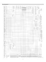
1. WHEN STARTING SWITCH IS TURNED ON, MONITOR PANEL DISPLAY DOES NOT APPEAR
·Before disconnecting the connector, always turn the starting switch OFF.
·Before carrying out below procedure, check all the related connectors are properly inserted and
short of fuse No.7, 11.
·After checking, insert the disconnected connectors again immediately unless otherwise specified.
Cause
YES
Defective cluster Replace
YES
Check voltage
between CN-56
(3) and (5)
Disconnection in Repair or replace
wiring harness or (after clean)
poor contact
between
CN-5-CN-56
Check voltage
between
NO CN- 5 (3) and (5)
Starting switch : ON
Voltage : 20~32V
Remedy
Starting switch : ON
Voltage : 20~32V
Disconnection in Repair or replace
wiring harness or (after clean)
poor contact
between CN-5 (3)
-GND or fuse
No.7, 11
NO
Check voltage
YES
20~32V
NO
0V
CLUSTER
FUSE
POWER(24V)
1
6
GND
3
3
POWER IG(24V)
5
5
NO.7
FUSE
NO.11
CN-56
CN-5
14W96ES01
6-25
2.
COMMUNICATION ERROR FLASHES ON THE CLUSTER (HCESPN 840, FMI 2)
·Before disconnecting the connector, always turn the starting switch OFF.
·Before carrying out below procedure, check all the related connectors are properly inserted.
·After checking, insert the disconnected connectors again immediately unless otherwise specified.
Cause
YES
Remedy
Defective cluster
Replace
YES Check voltage
between CN-56
(4, 8) and (3)
Check voltage
between
CN-5 (1) and (2)
Starting switch : ON
Voltage : 2V
Starting switch : ON
Voltage : 2V
Disconnection in Repair or replace
wiring harness or (after clean)
poor contact
between CN-56
(4, 8)-CN-5 (1, 2)
NO
Defective MCU
Replace
Disconnection in Repair or replace
wiring harness or (after clean)
poor contact
between CN-5 (1,
2)- CN-51(23, 33)
NO
Check voltage
YES
2V
NO
0V
CLUSTER
GND
3
3
MCU
RS485 RX
8
2
23
RS485 TX
RS485 TX
4
1
33
RS485 RX
CN-51
CN-56
CN-5
14W96ES02
6-26
3.
BATTERY CHARGING WARNING LAMP LIGHTS UP
UP(Starting switch : ON)
·Before disconnecting the connector, always turn the starting switch OFF.
·Before carrying out below procedure, check all the related connectors are properly inserted.
·After checking, insert the disconnected connectors again immediately unless otherwise specified.
Cause
YES
YES Check voltage
between CN-51
(39) and chassis
Check voltage
YES
between CN-2
(9) and chassis
NO
Voltage : 20~32V
Voltage : 20~32V
Check voltage
between alternator
terminal "2" and
chassis
Remedy
Defective MCU
Replace
Disconnection in
wiring harness or
poor contact
between CN-51
(39)-CN-2 (9)
Repair or replace
(after clean)
Disconnection in Repair or replace
wiring harness or (after clean)
poor contact
between CN-2 (9)
alternator terminal
"2"
NO
Engine : Running
Voltage : 20~32V
Defective alternator Replace
NO
Check voltage
YES
20~32V
NO
0V
ALTERNATOR
MCU
B+
1
39
9
2
3
4
P
L
FI
NC
G
3~
U
CN-74
CN-51
CN-2
17W96ES03
6-27
4.
WHEN COOLANT OVERHEAT WARNING LAMP LIGHTS UP (engine is started)
·Before disconnecting the connector, always turn the starting switch OFF.
·Before carrying out below procedure, check all the related connectors are properly inserted.
·After checking, insert the disconnected connectors again immediately unless otherwise specified.
Cause
YES
Remedy
Check use HRDT Check or replace
Check resistance
YES between engine
harness connector
(15)-(38)
Spec : 180Ω~160 kΩ
Disconnection in Repair or replace
wiring harness or (after clean)
poor contact
between temp
sensor-engine
harness connector
NO
Check resistance
between temp
sensor (A)-(B)
Starting switch : OFF
Spec : 180Ω~160 kΩ
See table
Defective coolant
temp sensor
NO
Replace
Check Table
Temperature (˚C )
0
25
50
80
95
Resistance (kΩ)
30~37
9.3~10.7
3.2~3.8
1.0~1.3
0.7~0.8
Engine ECM
SERVICE TOOL
CAN Lo
F
21
31
CAN Hi
E
20
21
RS232 TX
C
16
24
RS232 RX
B
15
34
P DUMP
A
9
12
CN-5
ENGINE COOLANT
TEMPERATURE SENSOR
CN-93
8
46
CAN_Hi
15
A
9
47
CAN_Lo
38
B
CN-3
OEM
connector
C
Engine harness
connector
CN-51
21096ES04
6-28
5.
WHEN AIR CLEANER WARNING LAMP LIGHTS UP (engine is started)
·Before disconnecting the connector, always turn the starting switch OFF.
·Before carrying out below procedure, check all the related connectors are properly inserted.
·After checking, insert the disconnected connectors again immediately unless otherwise specified.
Cause
YES
Clogged air filter or Check filter or
defective switch
replace switch
Does display go
off when
disconnect
CD-10?
Starting switch : ON
Engine : Start
Remedy
YES
Check resistance
between CN-53
NO
(23) and chassis
Starting switch : OFF
Disconnect CN-53
NO
Short circuit in
wiring harness
between CD-10CN-53 (23)
Repair or replace
(After clean)
Defective MCU
Replace
Check resistance
YES
MAX 1Ω
NO
MIN 1MΩ
AIR CLEANER SWITCH
MCU
Pa
23
CD-10
CN-53
21096ES05
6-29
6.
WHEN ENGINE OIL PRESSURE WARNING LAMP LIGHTS UP (engine is started)
·Before disconnecting the connector, always turn the starting switch OFF.
·Before carrying out below procedure, check all the related connectors are properly inserted.
·After checking, insert the disconnected connectors again immediately unless otherwise specified.
Cause
NO
Defective circuit,
sensor or ECM.
Remedy
Contact Cummins.
NO Fault code 135
active?
Starting switch : ON
Fault code 386
active?
Voltage above
Refer to engine
normal or shorted fault code 135
to high source
YES
Starting switch : ON
Voltage above
Refer to engine
normal or shorted fault code 386
to high source
YES
Signal
ENGINE OIL
PRESSURE SENSOR
CN-93
8
46
Engine
ECM
47
9
SERVICE TOOL
CAN_Lo
F
21
31
CAN_Hi
E
20
21
RS232_TX
C
16
24
RS232_RX
B
15
34
P_DUMP
A
9
12
CN-5
CN-3
OEM
connector
Return
13
38
3
2
33
1
Engine harness
connector
+5V supply
CN-51
21096ES06
6-30
7.
WHEN HYDRAULIC OIL TEMPERATURE WARNING LAMP LIGHTS UP (engine is started)
·Before disconnecting the connector, always turn the starting switch OFF.
·Before carrying out below procedure, check all the related connectors are properly inserted.
·After checking, insert the disconnected connectors again immediately unless otherwise specified.
Cause
YES
Remedy
High temperature
Check hydraulic
oil temperature
(105˚C±2˚C),
Defective temp
sensor
Replace
Short circuit
between temp
sensor and MCU
Repair or replace
Resistance
YES between CD-1
(1, 2) is in range
of 164~151Ω?
Does display go
off when
disconnect
CD-1?
Starting switch : ON
Engine : Start
Starting switch : ON
Disconnect CD-1
NO
YES
Resistance
between CN-51
NO (36, 5) is 0~1Ω?
Starting switch : OFF
Disconnect CN-51
Defective controller Replace
NO
Check Table
Temperature (˚C )
Resistance (kΩ)
~ -30
~ -10
22.22 8.16
~31.78 ~10.74
~0
~ 40
5.18
~ 6.6
~ 70
~ 80
~ 90
~ 100
1.06
0.39 0.322 0.243 0.185 0.164
~1.28 ~0.476 ~0.298 ~0.219 ~0.167 0.151
MCU
HYDRAULIC OIL
TEMPERATURE SENDER
36
2
5
1
C
CD-1
CN-51
21096ES07
6-31
105~
8. WHEN COOLANT TEMPERATURE GAUGE DOES NOT OPERATE (HCESPN 304,
FMI 3 or 4)
·Before disconnecting the connector, always turn the starting switch OFF.
·Before carrying out below procedure, check all the related connectors are properly inserted.
·After checking, insert the disconnected connectors again immediately unless otherwise specified.
Cause
YES
Remedy
Check use HRDT Check or replace
Check resistance
YES between engine
harness connector
(15)-(38)
Spec : 180Ω~160 kΩ
Disconnection in Repair or replace
wiring harness or (after clean)
poor contact
between temp
sensor-engine
harness connector
NO
Check resistance
between temp
sensor (A)-(B)
Starting switch : OFF
Spec : 180Ω~160 kΩ
See table
Defective coolant
temp sensor
NO
Replace
Check Table
Temperature (˚C )
0
25
50
80
95
Resistance (kΩ)
30~37
9.3~10.7
3.2~3.8
1.0~1.3
0.7~0.8
Engine ECM
SERVICE TOOL
CAN Lo
F
CAN Hi
21
31
E
20
21
RS232 TX
C
16
24
RS232 RX
B
15
34
P DUMP
A
9
12
CN-5
ENGINE COOLANT
TEMPERATURE SENSOR
CN-93
8
46
CAN_Hi
15
A
9
47
CAN_Lo
38
B
CN-3
OEM
connector
C
Engine harness
connector
CN-51
21096ES04
6-32
9. WHEN FUEL GAUGE DOES NOT OPERATE
OPERATE(HCESPN 301, FMI 3 or 4)
·Before disconnecting the connector, always turn the starting switch OFF.
·Before carrying out below procedure, check all the related connectors are properly inserted.
·After checking, insert the disconnected connectors again immediately unless otherwise specified.
Cause
YES
YES
Check resistance
between fuel
sender (1) and
(2)
Remedy
Defective MCU or Replace
cluster
Check resistance
between CN-51
(5) and (38)
Starting switch : OFF
Disconnect CN-51
Spec : 50~600Ω
NO
Starting switch : OFF
Spec : 50~600Ω
See table
NO
Disconnection in
wiring harness or
poor contact
between fuel
sender-MCU
Repair or replace
Defective fuel
sender
Replace
Check Table
Range
Resistance (Ω)
Range
Resistance (Ω)
Full
50
5/12
400
11/12
100
4/12
450
10/12
150
3/12
500
9/12
200
2/12
550
8/12
250
1/12
600
7/12
300
Empty warning
700
6/12
350
-
-
MCU
FUEL LEVEL SENDER
38
2
5
1
CD-2
CN-51
21096ES09
6-33
10. WHEN SAFETY SOLENOID DOES NOT OPERATE
·Before disconnecting the connector, always turn the starting switch OFF.
·Before carrying out below procedure, check all the related connectors are properly inserted and
short of fuse No.23.
·After checking, insert the disconnected connectors again immediately unless otherwise specified.
Cause
YES
Hydraulic system
malfunction
YES Check operation
of solenoid
NO
YES
Check resistance
YES between CN-4
(16) and chassis
Starting switch : ON
Voltage : 20~30V
Safety state
Check voltage
between CN-68
NO
(2) and chassis
Check hydraulic
system
Defective solenoid Replace
Safety lever : ON-OFF
Check voltage
between CN-68
(1) - (2)
Remedy
Starting switch : OFF
Safety state
Spec : 0Ω
Disconnect CN-4
YES
Check resistance
between CS-4
NO
(A)-(C)
Starting switch : OFF
Safety switch : ON-0Ω
OFF-∞
Safety lever : OFF
Starting switch : ON
Voltage : 20~30V
NO
NO
Disconnect in
wiring harness or
poor contact
between
CN-4-CN-68
Repair or replace
(after clean)
Disconnect in
wiring harness or
poor contact
between
CN-4-CS-4
Repair or replace
(after clean)
Defective safety
switch
Replace
Disconnection in
wiring harness
between
CN-68 (2)-fuse
Repair or replace
FUSE
NO.23
SAFETY SWITCH
C
B
A
A
14
B
15
2
C
16
1
SAFETY SOLENOID
CN-68
CS-4
CN-4
21096ES10
6-34
11. WHEN TRAVEL SPEED 1, 2 DOES NOT OPERATE (HCESPN 167, FMI 5 or 6)
·Before disconnecting the connector, always turn the starting switch OFF.
·Before carrying out below procedure, check all the related connectors are properly inserted and
short of fuse No.25 .
·After checking, insert the disconnected connectors again immediately unless otherwise specified.
Cause
YES
Disconnection in Repair or replace
wiring harness or
poor contact
between CN-70CN-52 or CN-181CN-52
Check resistance
YES between CN-70
(1)-(2) or
CN-181(1)-(2)
Starting switch : OFF
Spec : 30Ω
Disconnect CN-70
YES Check fault code
Remedy
Defective solenoid Replace
NO
167 active?
YES
Defective hydraulic Check hydraulic
system
system
Starting switch : ON
Check voltage
between CN-70
NO (1)-(2) or
CN-181(1)-(2)
Check if travel
speed lamps(
,
) change when
turning the RH
multifunction switch
on the cluster
Starting switch : ON
Spec : 20~30 V
Disconnect CN-70
Disconnection in Repair or replace
wiring harness or
poor contact
between CN-70fuse No. 25 or CN181-fuse No.25
NO
Starting switch : ON
YES
Defective cluster
Replace
Defective MCU
Replace
Check MCU
Y
NO
R
G
Starting switch : ON
NO
TRAVEL HIGH SPEED SOLENOID
FUSE
2
NO.25
1
MCU
CN-70
TRAVEL LOW SPEED SOLENOID
2
8
1
CN-181
CN-52
14W96ES11
6-35
lights up condition)
chassis
Check voltage
CN-3 (13) and
chassis
YES
Starting switch : ON
Spec : 20~30V
Disconnection in
NO wiring harness or
Key switch : ON
Spec : 20~30V
BATT (+)
BATT (+)
BATT (-)
BATT (-)
Check voltage
magnet coil and
chassis
Starting switch : START
1
2
NO.9
Check operation
of start relay
NO
CR-23
YES
YES Check voltage
between CN-2
(7) and chassis
Starting switch : START
Starting switch : ON
NO
Starting switch : START
Spec : 20~30V
Check operation
of anti-restart
NO relay CR-5
YES
Check voltage
between CR-5
NO
(1, 2)
5
5
6
6
3 2
ECM POWER RY
CR-35
NO.4
ⓐ
NO.20
POWER RY
CS-74
Disconnection in Repair or replace
wiring harness or
poor contact
between CN-2 (7)
-CR-5 (5)
1
2
CN-95
2
1
NO
Defective antirestart relay
Replace
Check voltage
between CR-23
and chassis
MASTER SW
FUSIBLE LINK
2
1
CN-60
CR-1
BATTERY
ⓑ
Starting switch : START
Spec : 20~30V
BATT RY
DO-1
YES
2
1
Defective start relay Replace
DIODE
NO
Starting switch : START
Spec : 20~30V
Disconnection in Repair or replace
wiring harness or
poor contact
between CN-2CR-5
CN-52
ANTI-RESTART RY
YES
Check voltage
between CR-5
(2) and chassis
Starting switch : START NO
Spec : 20~30V
15
MCU
CR-5
1 5 4
ⓑ
2
3
3
4
CIRCUIT BREAKER
MANUAL RESET
ⓐ
4 5 1
Defective start relay Replace
NO
Starting switch : START
Spec : 20~30V
5
CR-45
Defective magnet Replace
of start motor
YES between starter
4
35
59
60
36
Replace
Defective ECM
power relay CR-45
YES
1
CN-5
Repair or replace
NO.1
Check operation
start motor
3
B
ENGINE ECM
poor contact
between CN-3
(13) -CN-93 (39)
NO
0, I
ST C
BR ACC
4
4
3
2
1
2
Defective ECM or Replace
battery
CN-94
CS-2
Check voltage
YES CN-93 (39) and
Remedy
H
H0 I
2
YES
13
14
15
START KEY SW
KEY IG
39
4
Cause
CN-93
CN-3
1
·Before disconnecting the connector, always turn the starting switch OFF.
·Before carrying out below procedure, check all the related connectors are properly inserted and
short of fuse No. 1, 4, 9, 20.
·After checking, insert the disconnected connectors again immediately unless otherwise specified.
CN-125
12. WHEN ENGINE DOES NOT START (
1
2
3
4
Disconnection in Repair or replace
wiring harness or
poor contact
between CN-52
(15)-CR-5 (1)
2 3
5
ANTI-RESTART RY
START MOTOR
CN-2
7
8
CR-23
2
1
START RY
Disconnection in Repair or replace
wiring harness or
poor contact
between CS-2 (6)CR-5 (2)
CN-45
17W96ES12
6-36
13. WHEN STARTING SWITCH ON DOES NOT OPERATE
CN-93
CN-94
BATT (+)
BATT (+)
BATT (-)
BATT (-)
Cause
YES Check voltage
between DO-1
(1) and chassis
Defective start
switch
NO
YES Check voltage
between CS-2
(1) and chassis
YES
Check voltage
between CN-5
NO
(36) and chassis
Check voltage
and specific
gravity of battery
YES
Voltage : 20~30V
Check voltage
between CS-74
NO
(1) and chassis
Specific gravity : MIN 1.28
Voltage : MIN 24V
Voltage : 20~30V
NO
1
2
NO.9
5
5
6
2
3
6
5
3 2
ECM POWER RY
CR-35
NO.4
Replace
4 5 1
3
4
NO.1
NO.20
POWER RY
CS-74
1
2
CN-95
2
1
CIRCUIT BREAKER
MANUAL RESET
Disconnection in Charge or replace
wiring harness or (after clean)
poor contact
between CS-74 (1)
-CN-5 (36)
MASTER SW
FUSIBLE LINK
2
1
CN-60
CR-1
ⓐ
Battery capacity
too low
NO
3
CR-45
Disconnection in Replace
wiring harness or
poor contact
between CS-2 (1)CN-5 (36)
Voltage : 20~30V
4
35
59
60
36
Disconnection in Repair or replace
wiring harness or (after clean)
poor contact
between DO-1 (1)CR-1 or defective
battery relay
Disconnection in Repair or replace
NO wiring harness or (after clean)
poor contact
between CS-2 (2)CN-5(60)- DO-1 (1)
Voltage : 20~30V
Starting switch : ON
2
CN-5
Remedy
Voltage : 20~30V
YES Check voltage
between CS-2
(2) and chassis
CS-2
B
ENGINE ECM
YES
ST C
BR ACC
1
0, I
2
4
3
2
1
4
H
H0 I
4
13
14
15
START KEY SW
KEY IG
CN-125
CN-3
39
1
·Before disconnecting the connector, always turn the starting switch OFF.
·Before carrying out below procedure, check all the related connectors are properly inserted, master
switch ON and check open circuit of fusible link (CN-60).
·After checking, insert the disconnected connectors again immediately unless otherwise specified.
BATTERY
BATT RY
DO-1
2
1
Charge or replace
(after clean)
DIODE
CN-52
YES
ⓐ
Check voltage
between CS-74
(2)- chassis
Defective master
switch
Replace
15
MCU
CR-5
1 5 4
NO
Voltage : 20~30V
ANTI-RESTART RY
Disconnection in Charge or replace
wiring harness or (after clean)
poor contact
between CS-74 (2)
-CR-1
1
2
3
4
2 3
5
ANTI-RESTART RY
START MOTOR
CN-2
7
8
CR-23
2
1
START RY
CN-45
17W96ES13
6-37
14. WHEN STARTING SWITCH IS TURNED ON, WIPER MOTOR DOES NOT OPERATE
·Before disconnecting the connector, always turn the starting switch OFF.
·Before carrying out below procedure, check all the related connectors are properly inserted and the fuse
No. 6, 17 and 18 is not blown out.
·After checking, insert the disconnected connectors again immediately unless otherwise specified.
CN-21
3
Cause
NO
Defective wiper
cut switch
Remedy
2
Replace
Front sliding door
open-close
YES
NO Check voltage
between CN-97
(7) and chassis
Front sliding door-close
Voltage : 4~5V
Check operation
YES of multifunction
SW
Starting switch : ON
Turn wiper switch
Check voltage between
CN-5 (23) and chassis
YES
ⓐ
NO
Check voltage CN-98
(5) and chassis
Sarting switch : ON
Voltage : 0~1V
Check operation
of wiper motor
and controller
check voltage
YES CN-141 (7) and
chassis, CN-21
(4) and chassis
Starting switch : OFF
Voltage : 20~30V
Check continuity
NO
between
CN-141 (2)-CN-98 (3),
CN-141 (9)-CN-97 (10),
CN-141 (10)-CN-98 (5),
CN-141 (5)-Chassis ,
Check wiper
CN-141 (1)-CN-21 (5),
motor resistance
CN-141 (3)-CN-21 (6),
YES between CN-21
CN-141 (4)-CN-21 (2),
(2)-CN-21 (6)
CN-141 (13)-CN-21 (3)
Resistance : 3~4Ω
NO
Check voltage
CN-141 (6) and
YES chassis
Starting switch : ON
Voltage : 20~30V
Defective
multifunction
switch
YES
YES
4
4
CN-5
M
2
6
FUSE
18
NO.6
CN-141
Replace
Replace
FEED BACK
1
MOTOR DRIVE SIG
2
MOTOR DRIVE-
3
1
MOTOR DRIVE+
4
2
GND
5
3
VCC
6
4
CONTINUE 24V
7
5
WASHER P/P
8
6
WASHER SIG.
9
7
INT. SIG
10
8
WIPER CUT SW
11
N.C
12
FEED BACK
13
WIPER MOTOR CONTROLLER
CN-17
FUSE
24
NO.18
CN-22
M
2
1
19
WASHER PUMP
CN-98
43
(2) INT
1
2
3
4
5
Replace
(1) COM
(4) HO
7 WA
CS-53
1
Repair or replace
(after clean)
Hi
8 COM
23
4
3
WIPER CUT SW
CN-97
1) Recheck fuse Replace
No.18
2) Disconnection Repair or replace
CN-141(6)-Fuse (after clean)
37
10
7
1
2
3
4
5
6
7
8
9
10
11
12
6
WI
2
Lo
4 COM
5
Lo
3
Hi
12 B+
9
L
10 COM
ⓑ
11
Disconnection in Repair or replace
wiring harness or (after clean)
poor contact
NO
3
WIPER MOTOR
1)Recheck fuse Replace
No.17
2)Disconnection in Repair or replace
wiring harness or (after clean)
poor contact
between
CN-97(7)-Fuse
Defective
multifunction
switch
1) Recheck fuse
No.6
2) Disconnection
in wiring harness
or poor contact
between
CN-141(7)-Fuse,
CN-21(4)-Fuse
Check voltage CN-97
(10) and chassis
Washing
ⓑ
Starting switch : ON
Vottage : 20~30V
NO
NO
Intermittent
ⓐ
6
Repair or replace
Short circuit in
wiring harness or (after clean)
poor contact
between CN-141
(11)- CS-53
Check valtage
between CN-141
YES (11) and chassis
5
5
NO
Check operation
wiper cut switch
1
Defective wiper
motor
Replace
Defective wiper
motor controller
Replace
R
MULTIFUNCTION SWITCH-LH
FUSE
NO.17
14W96ES14
6-38
15. WHEN STARTING SWITCH IS TURNED ON, HEAD LAMP DOES NOT LIGHTS UP
·Before disconnecting the connector, always turn the starting switch OFF.
·Before carrying out below procedure, check all the related connectors are properly inserted and
short of fuse No.17.
·After checking, insert the disconnected connectors again immediately unless otherwise specified.
FUSE
CN-151
NO.17
Cause
YES
Check voltage
YES between CL-4(2)
and chassis,CL3(2) and chassis
Voltage : 20~30V
NO
YES
Check voltage
between CN-98
NO
(2) and chassis
Starting switch : ON
NO
Head lamp switch : ON
Voltage : 20~30V
Check voltage
between CN-152
(14) and chassis,
CN-152 (15) and
chassis
INT (2)
COM (1)
Replace
HO (4)
1
2
3
4
CN-97
Check voltage
YES
between CN-151
(8) and chassis
Starting switch : ON
Head lamp switch : ON
Voltage : 20~30V
Defective bulb
Remedy
Disconnection in Repair or replace
wiring harness or (after clean)
poor contact
between CN-151
(8)-CL-4 (1) or
CN-151(8)-CL-3(2)
WA
7
Hi
1
Disconnection in
wiring harness or
poor contact
between CN-98
(2)-CN-151 (9)
YES
Lo
Replace
Lo
Repair or replace
(after clean)
6
2
5
Hi
3
B+
12
L
9
1
2
3
4
5
6
7
8
9
10
11
12
CN-98
1
2
COM 10
R
Check voltage
between CN-5
NO (49) and chassis
Disconnection in
wiring harness or
poor contact
between CN-152
(14) and chassis or
CN-152 (15)chassis
Recheck fuse
No. 17
Replace
Defective switch
panel
Replace
CABIN LAMP RY
WORK LAMP RY(COIL)
WORK LAMP RY
WORK LAMP RY
RELAY EARTH
HEAD LMP RY HI
HEAD LMP RY HI(COIL)
HEAD LMP RY LO
NC
OUTRINGER RY
HARNESS RY
1
2
3
4
5
6
7
8
9
10
11
12
13
14
15
FUEL HEAT RY(COIL)
FUEL HEAT RY
HEAD LMP RY LO(COIL)
HEAD LMP RY(COIL)
REAR LH RY
REAR RH RY
FRONT LH RY
FUEL HEAT RY
FRONT RH RY
REAR LH RY(COIL)
REAR RH RY(COIL)
FRONT LH RY(COIL)
FRONT RH RY(COIL)
HEAD LMP RY
HEAD LMP POWER RY
HARNESS RY
11
MULTIFUNCTION SW-LH
Repair or replace
(after clean)
CABIN LAMP RY
CN-152
WI
CN-5
ILL
HEAD LAMP
WORK LAMP
CABIN LAMP
PRE-HEAT
Front/ Left
Front/ Right
Rear/ Left
Rear/ Right
POWER
GND
DOZER PS
1
2
3
4
5
6
7
8
9
10
11
12
CL-4
1 Lo
2 Hi
CN-116
Starting switch : ON
Voltage : 20~30V
Head lamp switch : ON
CABIN LAMP RY(COIL)
12
COM 8
COM 4
Defective
multifunction
switch
7
1
2
3
4
5
6
7
8
9
10
11
12
3
49
E
HEAD LAMP-RH
CL-3
1 Lo
2 Hi
3
E
HEAD LAMP-LH
SWITCH PANEL
Starting switch : ON
Voltage : 20~30V
Head lamp switch : ON
YES
Check voltage
between CN-116
NO
(2) and chassis
Starting switch : ON
Head lamp switch :
ON-OFF
NO
14W96ES15
Disconnection in Repair or replace
wiring harness or (after clean)
poor contact
between CN-5(49)
and CN-116(2)
6-39
16. WHEN STARTING SWITCH IS TURNED ON, WORK LAMP DOES NOT LIGHTS UP
·Before disconnecting the connector, always turn the starting switch OFF.
·Before carrying out below procedure, check all the related connectors are properly inserted and
short of fuse No.15.
·After checking, insert the disconnected connectors again immediately unless otherwise specified.
Cause
YES
YES
Defective bulb
Remedy
Replace
Check voltage
between CL-5 (2)
and chassis
FUSE
NO.15
NO
YES Check voltage
between CN-151
(5) and chassis
Starting switch : ON
Work lamp switch : ON
Voltage : 20~30V
Check voltage
between CN-151
(6) and chassis,
CN-151(4) chassis
YES
Check voltage
between CN-116
NO
(3) and chassis
Starting switch : ON
Work lamp switch : ON NO
Voltage : 20~30V
Starting switch : ON
Voltage : 20~30V
NO
Disconnection in Repair or replace
wiring harness or (after clean)
poor contact
between CN-151
(5)-CL-5 (2)
Defective switch
panel
CN-5
CN-151
CN-116
Replace
Disconnection in Repair or replace
wiring harness or (after clean)
poor contact
between CN-151
(5)-CN-116 (3)
ILL
1
HEAD LAMP
2
WORK LAMP
3
CABIN LAMP
4
PRE-HEAT
5
Front/ Left
6
Front/ Right
7
Rear/ Left
8
50
CABIN LAMP RY(COIL)
CABIN LAMP RY
CABIN LAMP RY
WORK LAMP RY(COIL)
WORK LAMP RY
WORK LAMP RY
RELAY EARTH
HEAD LMP RY HI
HEAD LMP RY HI(COIL)
HEAD LMP RY LO
NC
OUTRINGER RY
HARNESS RY
CN-12
CL-5
9
2
1
POWER
10
1
2
GND
11
DOZER PS
12
Rear/ Right
WORK LAMP
SWITCH PANEL
Disconnection in Repair or replace
wiring harness or (after clean)
poor contact
between CN-151
(6) and chassis or
CN-151 (4) and
chassis
Recheck fuse
No.15
1
2
3
4
5
6
7
8
9
10
11
12
1
2
CL-6
Replace
14W96ES16
6-40