TÀI LIỆU HỆ THỐNG PHANH (THẮNG) wabco
Bạn đang xem bản rút gọn của tài liệu. Xem và tải ngay bản đầy đủ của tài liệu tại đây (1.69 MB, 61 trang )
Systems And
Components In
Commercial Vehicles
2. Edition
Copyright WABCO 2005
Vehicle Control Systems
An American Standard Company
8150100033
The right of amendment is reserved
Version 002/09.01(en)
815 010 003 3
Table of Contents
Page
Operation of Air Braking Systems ..................................................... 4
1.
Motor Vehicles
Braking System
............................................................................. 6
Components of the Motor Vehicle’s Braking System........................... 7
2.
Trailers
Braking System
........................................................................... 64
Equipment For Trailer Braking Systems ............................................ 66
3.
Anti-Lock Braking System (ABS) .................................................... 83
4.
Sustained-Action Braking Systems On Motor Vehicles ................ 95
5.
EBS - Elektronisch geregeltes Bremssystem ............................... 101
6.
Air Suspension Systems and ECAS
(Electronically Controlled Air Suspension)................................... 111
7.
Clutch Servo..................................................................................... 123
8.
Air Braking Systems In
Agricultural Vehicles ....................................................................... 127
9.
ETS and MTS - Elektronic Door Control Systems
For Motor Coaches .......................................................................... 137
10. Installation Of Pipes And Screw Unions ....................................... 151
11. Index ................................................................................................. 163
1
3
Operation of Air Braking Systems
1. Compressed Air Supply
The compressed air supplied by the compressor (1) flows to the air dryer (3) via
the unloader (2) which automatically controls the pressure within the system within a range of between 7.2 and 8.1 bar, for
instance. In the air dryer, the water vapour in the air is extracted and expelled
through the air dryer’s vent. The dried air
then flows to the quadruple-circuit protection valve (4) which, if one or several
circuits are defective, secures the intact
circuits against any loss in pressure.
Within the service braking circuits I and
II, the air supply from the reservoirs (6
and 7) flows to the brake valve (15). In
Circuit III the air supply from the reservoir
(5) flows through the 2/2-way valve which
is integrated in the trailer control valve
(17) to the automatic hose coupling (11)
and on to the check valve (13), the hand
brake valve (16) and the relay valve (20)
into the spring-loaded portion of the Tristop spring brake actuators (19). Circuit IV
supplies air to any ancillary consumers,
in this case an exhaust brake.
The trailer’s braking system receives
compressed air through the hose coupling (11) with its supply hose connected.
This air then passes the line filter (25)
4
and the relay emergency valve (27) before reaching the reservoir (28) and also
flows to the supply ports of the ABS relay
valves (38).
2. Operation:
2.1 Service Braking System
When the brake valve (15) is actuated,
compressed air flows via the ABS solenoid control valve (39) into the brake
chambers (14) of the front axle and to the
load-sensing valve (18). This valve reverses and the air flows via the ABS solenoid control valve (40) into the service
brake portion (brake chambers) of the
Tristop spring brake actuators (19). The
pressure in the brake cylinders generating the force required for the wheel brake
depends on the amount of force applied
to the brake valve, and on the load carried on the vehicle. This brake pressure
is controlled by the load-sensing valve
(18) which is connected to the rear axle
by means of a linkage. Any change in the
distance between the vehicle’s chassis
and its axle caused by loading or unloading the vehicle causes the brake pressure to be continuously adjusted. At the
same time, via a pilot line, the load-empty
valve integrated in the brake valve is affected by the load-sensing valve. Thus
the brake pressure on the front axle is
also adjusted to the load carried on the
vehicle (mostly on lorries).
The trailer control valve (17) actuated by
the two service braking circuits pressurizes the pilot connection of the relay emergency valve (27) after passing the hose
coupling (12) and the connecting “control“ hose. The air supply from the air reservoir (28) is thus allowed to pass
through the relay-emergency valve, the
trailer release valve (32), the adapter
valve (33) and on to the load-sensing
valve (34) and the ABS relay valve (37).
The relay valve (37) is actuated by the
load-sensing valve (34) and the compressed air flows to the brake chambers
(29) on the front axle. The ABS relay
valves (38) are actuated by the loadsensing valve (35), and the compressed
air is allowed to pass to the brake chambers (30 and 31). The service pressure
on the trailer, which is similar to the output pressure from the towing vehicle, is
automatically adjusted by the load-sensing valves (34 and 35) for the load carried
on the trailer. In order to prevent overbraking of the wheel brake on the front
axle in the partial-braking range, the
service pressure is reduced by the adapter valve (33). The ABS relay valves (on
Operation of Air Braking Systems
the trailer) and the ABS solenoid control
valves (on the towing vehicle) are used to
control (pressure increase, pressure
hold, pressure release) the brake cylinders. If these valves are activated by the
ABS ECU (36 or 41), this control process
is achieved regardless of the pressure allowed to pass by the brake valve or the
relay emergency valve.
When they are not needed (solenoids are
dead), the valves operate as relay valves
and achieve a faster increase or decrease of the pressure for the brake cylinders.
2.2 Parking Braking System
When the hand brake valve (16) is actuated and locked, the spring-loaded portions of the Tristop spring brake
actuators (19) are exhausted fully. The
force needed for the wheel brake is now
provided by the heavily preloaded
springs of the Tristop spring brake actuators. At the same time, the pressure in
the line leading from the hand brake
valve (16) to the trailer control valve (17)
is reduced. Braking of the trailer commences by the pressure increasing in the
connecting ‘supply’ hose. Since the
guideline of the Council of the European
Communities (RREG) that a tractor-trail-
er combination must be held by the motor
vehicle alone, the pressure in the trailer’s
braking system can be released by moving the hand brake lever into its ‘control’
position. This permits the parking braking
system to be examined as to whether it
fulfills the provisions of the RREG.
2.3 Auxiliary Braking System
Due to sensitive graduation of the hand
brake valve (16) the lorry can be braked
by means of the spring-loaded portions
even if the service braking systems I and
II have failed. The brake force for the
wheel brake is produced by the force of
the preloaded springs of the Tristop
spring brake actuators (19) as described
under ‘Parking Braking System’ although
the spring-loaded portions are not exhausted fully but only to the extent required for the braking performance.
3. Automatic Braking of the
Trailer
In the event of the connecting ‘supply’
line breaking, the pressure will drop rapidly and the relay emergency valve (27)
will cause full application of the trailer’s
brakes. In the event of the connecting
‘control’ line breaking, the 2/2-way valve
integrated in the trailer control valve (17)
will, when the service braking system is
actuated, throttle the passage of the supply line leading to the hose coupling (11)
to such an extent that the rupture of the
supply line causes a rapid drop in pressure in the supply line and the relay
emergency valve (27) causes the trailer
to be braked automatically within the legally stipulated time of no more than 2
seconds. The check valve (13) secures
the parking braking system against any
inadvertent actuation if the pressure
drops in the supply line leading to the
trailer.
4. ABS Components
The motor vehicle usually has three telltale lamps (ASR having one additional
lamp) fitted for indicating functions and
for continuously monitoring the system. It
also has a relay, an information module
and an ABS socket (24).
After actuating the driving switch, the yellow telltale lamp will come on if the trailer
has no ABS or if the connection has not
been established. The red lamp will go off
when the vehicle exceeds a speed of approx. 7 k.p.h. and the safety circuit of the
ABS electronics has not detected an error.
5
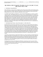
Air braking system with ABS/ASR (4S/4M)
4,5
36
38
2
3
12
21
7
8
20
22
1
10
14
13
37
11
9
16
17
33
6
23
28
18
27
29,30
31,32
24
15
19
25
34
26
35
Legend:
Pos.
1
2
3
4
5
6
7
8
9
10
11
12
13
14
6
Compressor
Air dryer with combined
unloader
Four circuit protection valve
Air reservoir
Clamps
Test coupling
Drain valve
Check valve
Brake valve with integral
auto load proportioning valve
Hand control valve with
trailer control
Relay valve
Piston cylinder
Brake chamber
ASR-Control cylinder
15
16
17
18
19
20
21
22
23
24
25
26
27
28
29
30
3/2 Solenoid valve
Tristop-Brake actuator
Quick release valve
Load sensing valve
Knuckle joint
Trailer control valve
Hose coupling, supply
Hose coupling, control
Two-Way valve
ABS Warning lamp
ABS Info lamp
ABS-socket
Sensor extension cable
Solenoid cable
Socket
Sensor braket
31
32
33
34
35
36
37
38
Sensor with cable
Pole wheel
ABS-Solenoid valve
Electronic control unit
Info module
Pressure switch
Proportional valve
3/2 Directional control valve
1.
Components Of The
Motor Vehicle’s Braking System
7
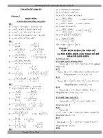
1.
Air Intake Filters
Moist Air Filter
432 600 . . . 0 to 432 607 . . . 0
Oil Bath Air Cleaner
432 693 . . . 0 to 432 699 . . . 0
Moist Air Filter
Oil Bath Air Cleaner
Purpose:
Operation:
To prevent impurities from the air getting
into the compressor (by using suction filters) or into the vents of compressed air
equipment (by using vent filters); they
also serve to muffle the noise caused by
the intake of air or by blowing it off.
Operation:
Moist air filters (for normal operating conditions). The air is taken in through an
opening in the cap, flows through the filter medium where it is cleaned and then
flows on to the air intake of the compressor.
8
Oil bath air cleaner (for air containing a
large mount of dust)
The air is taken in through the sieve plate
below the cap and the central pipe, and
then passed across the surface of the oil
where any dust particles can settle. From
the surface of the oil, the air is pushed
upward, flows through a filter package
which retains any impurities which may
still be contained in the air and any oil
particles carried over before reaching
the air intake of the compressor.
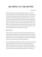
Compressor
1.
Single Cylinder
Air Compressor
411 1 . . . . . 0 and
911 . . . . . . 0
Twin Cylinder
Air Compressor
411 5 . . . . . 0 and
911 5 . . . . . 0
Purpose:
Production of compressed air for road
vehicles and static systems.
Operation:
The pulley on the end of the crankshaft is
rotated by a vee-belt driven off the vehicle’s engine. This rotation causes the
connecting rods to to move the pistons.
As the piston travels downwards clean
air from either the engine air cleaner or
the moist air filter (or alternatively an oil
bath air cleaner) is drawn in trough the
inlet valve. As the piston moves upwards, the inlet valve closes, and air is
pumped through the delivery valve into
the the reservoir.
The type of lubrication depends on the
construction of the compressor, and can
be splash or pressure fed.
9
1.
Air Cleaner
Air Cleaner
432 511 . . . 0
Purpose:
To clean the air delivered by the compressor and to precipitate the humidity it
contains.
Operation:
The air entering at port 1 flows through
annular gap A into Chamber B. As it
passes through the gap A, the air cools
and some of the water vapour it contains
will condensate. The air then flows
through the filter (a) to Port 2.
At the same time, the pressure in Chamber B opens the inlet (3) of the valve
body (d) and the condensate runs
through the filter (f) into Chamber C. As
10
the pressure in Chamber B falls, the inlet
(3) closes and the outlet (b) opens. The
condensate is now blown outside by the
pressure in Chamber C. When the pressures in Chambers B and C are balanced, outlet (b) closes.
Pin (C) can be used to check whether the
automatic drain valve is working properly.
Air Dryer
432 420
Air Dryer
432 410 . . . 0 and
432 420 . . . 0
Purpose:
Drying of the compressed air supplied by
the compressor by extracting the moisture present in the air. This is effected by
a progress of cold regenerated adsorption drying where the air compressed by
the compressor is led through granulates
(adsorbens) capable of adsorbing the
moisture contained in the air.
Operation:
Variant 1 (Control Via Separate Unloader Valve 432 420 ... 0)
In the feed phase, the compressed air
supplied by the compressor flows via
Port 1 into Chamber A. Here the condensate caused by the reduction in temperature will collect, reaching Outlet (e) via
Duct C.
Via Fine Filter (g) integrated in the cartridge, and via Annulus (h), the air will
reach the upper side of Desiccant Cartrige (b), being cooled in the process,
and further condensate will precipitate.
Moisture is extracted from the air as it
passes through Granulate (a) this moisture is absorbed by the surface and the
fine ducts [diameter: 4 x 10⁶ m = 4Å
(Angström)] of the extremely porous
granulate.
Since the oil molecules are more than 4Å
in size they cannot enter the fine ducts of
the granulates. This makes the granulate
robust. The steam portion of the oil is not
adsorbed. The dried air reaches the air
reservoirs via Check Valve (c) and Port
21. At the same time, the dried air also
reaches the re-generation reservoir via
throttling port and Port 22.
When cut-out pressure in the system is
reached, Chamber B is pressurized from
the unloader valve via Port 4. Piston (d)
moves downwards, opening Outlet (e).
The air, the condensate plus any impurities and oil carbon from Chamber A will
be emitted via Duct C and Outlet (e).
When cut-in pressure at the unloader
valve is reached, Chamber B is vented
once again. Outlet (e) closes and the drying process will commence as described
above.
1.
432 410
Variant 2 (Control Via Integral Unloader Valve 432 410 ... 0)
The process of drying the air is as described under Variant 1 In this version,
however, the cut-out pressure will reach
Chamber D via Bore (l), acting on Diaphragm (m). After overcoming the spring
resistance, Inlet (n) will open, and Piston
(d), now pressurized, will open Outlet (e).
The air supplied by the compressor will
now be emitted via Chamber A, Duct C
and Vent 3. Piston (d) also acts as a
pressure relief valve. In the event of any
excess pressure, Piston (d) will automatically open Outlet (e). If, due to air
consumption, the supply pressure in the
system falls to a value below cut-in pressure, Inlet (n) will close and the pressure
from Chamber B will be reduced via the
unloader valve's vent. Outlet (e) will
close and the drying process will commence once again.
Any malfunction due to icing in extreme
conditions in the area of Piston (d) can
be prevented by fitting a Heating Cartridge (g) which will switch on at temperatures below 6°C and switch off again
when the temperature reaches approx.
30°C.
11
1.
Air Dryer
432 413
Air Dryer With Return-Flow
Limiting Valve
432 413 . . . 0 and
432 415 . . . 0
The single-chamber air dryers from this
series have an integrated return-flow limiting valve which permits the required
amount of air to be taken from the main
reservoir provided the multiple-circuit
protection valve permits a return flow.
Thus no separate regenerating reservoir
is required.
Operation:
Variant 1 (Control Via Separate Unloader Valve 432 413 ... 0)
In the delivery phase the compressed air
supplied by the compressor flows
through Port 1, opens the check valve (i)
and flows into Chamber A. Due to the
drop in temperature, condensation water
collects there which reaches the outlet
(e) through Duct C.
The air is dried as described under 432
420. At the same time, dried air also
flows into Chamber E, pressurizing diaphragm (o). This arches towards the
right, releasing the passage between
Chambers E and G via Throttling Port (s).
The air supply also reaches Chamber H
via Filter (l), pressurizing Valve (q). Once
12
the force of the pressure spring, preset
by means of Screw (r), has been overcome, Valve (q) is lifted. The air supply
will now reach Chamber F, acting on the
other side of the diaphragm (o) with a
slightly lower pressure in keeping with
the retention of Valve (q).
When the cut-off pressure within the system has been reached, Chamber B is
pressurized by the unloader via Port 4.
The piston (d) moves downwards and
opens the outlet (e). The check valve (i)
closes the passage to Port 1 and the air
from Chamber A flows through Duct C
and is emitted to atmosphere at the outlet
(e).
Due to the drop in pressure in Chamber
G, the check valve (c) closes. The air to
be regenerated is now taken from the air
reservoirs, which is why a multiple-circuit
protection valve must permit its return
flow. The air supply at Port 21 flows
through Chamber E, the throttling port (s)
where it expands, on into Chamber G
and thus to the underside of the granulate cartridge (b).
As it passes through the granulate cartridge (b) in an upward direction, the humidity on the surface of the granulate (a)
is taken up by the air and emitted to atmosphere at Vent 3 after passing Duct C
and the opened outlet (e). The return flow
is completed when the pressure on the
432 415
left of the diaphragm (q) has been reduced to a point where it reaches its closing position.
When the cut-in pressure at the unloader
is reached, the pressure in Chamber B is
reduced once again. The outlet (e) closes and the drying process starts again as
described above. Outlet 31 also has a
safety valve for the pressure side.
Variant 2 (Control Via Integral Unloader Valve 432 415 ... 0)
In this variant, the cut-off pressure reaches Chamber J via the connecting hole
into Chamber J and acts on the diaphragm (m). After the spring force has
been overcome, the inlet (n) opens and
the piston (d) which is now pressurized
opens the outlet (e).
The air delivered by the compressor now
flows through Chamber A, Duct C and is
emitted to atmosphere at Vent 3. The piston (d) at the same time acts as a pop
valve. When the pressure is excessive,
the piston (d) automatically opens the
outlet (e).
If air consumption causes the supply
pressure within the system to fall below
the cut-in pressure, the inlet (n) closes
and the pressure from Chamber B is reduced through the vent of the unloader
valve. The outlet (e) closes and the drying process begins again.
Air Dryer
1.
432 431
Twin Chamber Air Dryer
432 431 . . . 0 and
432 432 . . . 0
Operation:
a) Control without Integral Unloader Valve
The compressed air supplied by the
compressor flows to Bore E via Port 1.
Due to a reduction in temperature, condensate may form at Bore E, reaching
Idling Control Valve (m) via Bore L. From
Bore E, the compressed air will pass
Valve (k), enter Chamber B, and reach
the upper side of Desiccant Cartridge (c)
via Fine Filter (e) integrated into the cartridge, and via Annulus A.
Through Sieve Plate (a), the pre-cleaned
compressed air will pass upwards
through Granulate (b) sewn into a filter
bag in Cartridge (c), reaching Bore G via
Sieve Plate (d) and Check Valve (f).
As the air passes through Granulate (b),
the inherent moisture is retained by the
extremely porous granulate. From Bore
G, the compressed air reaches the air
reservoirs through Check Valve (g) and
via Port 2.
Through the throttling port of Valves (f
and p) designed according to the swept
volume of the compressor used, part of
the dried compressed air from Bore G
will reach the underside of Cartridge (s),
passing Granulate (r) in an upward direction (backflush). In this process, the
moisture adhering to the fine ducts of the
extremely porous Granulate (r) is taken
up by the dried air and reaches Vent 3
via Annulus K, Chamber H and past the
open rear side of Valve (o).
The additional Charging Valve (h) ensures that Control Valves (k and o) do
not switch over when the system is filled
initially. Valve (h) will not open until a
supply pressure of > 5 bar has been
reached at Port 2, permitting compressed air to reach Chamber C. If the
timeswitch element integrated in the solenoid valve then opens the current supply to Trip Coil (j), Armature (i) will be
attracted. Compressed air from Chamber C will now flow into Chamber D and,
via Bore F, into Chamber M, moving the
control valves against the spring force
into their end positions on the left.
The passage from Bore E to Chamber B
is closed. The compressed air present in
Chamber B will now be emitted at Port 3
after passing by the open rear side of
Control Valve (k) and going through Bore
N. Check Valve (g) will close and the
pressure in the system continues to be
ensured. As a consequence of the pressure reduction in Chamber B, Check
Valve (f) will also close.
The compressed air supplied by the
compressor will now flow from Bore E
through Chamber H, Annulus K and
through Granulate (r) of Cartridge (s).
The drying process of the compressed
air is as described before. After Valve (p)
and Check Valve (g) have opened, the
dried air reaches the reservoirs via Port
2. Through the throttling port of Valve (f),
dried air reaches the underside of Granulate (b), causing a back-flushing process to take place here, too.
After approx. 1 minute, the time-switch
element will break the current supply to
the trip coil. Armature (i) will close the
passage from Chanber C, opening the
vent, thus reducing the pressure in
Chambers D and M. Through the spring
force and the pressure in Bore G, the
control valves are returned to their end
positions on the right. Control Valve (o)
will close the passage to Chamber H,
and Control Valve (k) will open the pas-
13
1.
Air Dryer
432 432
sage to Chamber B. The compressed air
supplied by the compressor is now again
fed into Granulate (b), and the drying
process will commence as described before, with alternating cartridges continuing to be used at one-minute intervals.
When the unloader valve switches to
idling once the input cut-out pressure has
been reached, pressure is being fed in at
Port 4, pressurizing, and moving downwards, Piston (m), opening the idling
control valve. Any condensate and impurities will be emitted together with the air
supplied in the idling phase via Vent 3.
When the unloader valve switches to
load, Port 4 is vented and the idling control valve closes the passage to Vent 3.
Any malfunction due to icing in extreme
conditions in the area of Piston (e) can
be prevented by fitting a Heating Cartridge (g) which will switch on at temperatures below 6°C and switch off again
when the temperature reaches approx.
30°C.
b)
Control Via Integral Unloader
Valve
The air is dried as described under a).
The pressure building up at Port 2 when
the system is being filled is also present
14
in Chamber P, pressurizing the underside of Diaphragm (t). As soon as the
force resulting therefrom is larger than
the force of Pressure Spring (n), Diaphragm (t) will arch, taking with it Piston
(q). This opens Inlet (u), and Piston (m),
now pressurized, is moved downward,
opening the idling control valve. Any condensate and impurities will be emitted together with the air supplied in the idling
phase via Vent 3. The compressor will
continue to run idle until the pressure
within the system has fallen to a value
below the unloader valve's cut-in pressure. The pressure in Chamber P below
Diaphragm (t) will fall simultaneously.
Pressure Spring (n) will move Piston (q)
and Diaphragm (t) back to their original
positions. Outlet (u) will close, and the
pressure from Chamber O will be reduced via the vent of the unloader valve.
The idling control valve with Piston (m)
will close once again. The compressed
air will now again flow into Bore E and
reach the air reservoirs via Port 2 after
being dried in Desiccant Containers (b or
r). The system is subsequently filled
once again up to the cut-out pressure of
the unloader valve.
Application:
Depending on the respective application,
WABCO provides Single and Twin
Chamber Air Dryers.
The decision of whether to use a Single
or a Twin Chamber Air Dryer will depend
on the compressor's swept volume and
on its duty cycle.
Single Chamber Air Dryers
can normally be used for applications up
to a swept volume of » 500 litres/minute
and a duty cycle of up to » 50%. Any deviations of these standard values should
be tested in road-test runs.
Twin Chamber Air Driers
cover the area > 500 litres/minute and >
50% up to 100% duty cycle. Swept volumes in excess of 1000 litres/ minute
should be tested in road-test runs
1.
Unloader
Combined Unloader
975 303 . . . 0
Purpose:
To automatically control the operating
pressure in an air braking system and to
protect its pipes and valves from contamination. Depending on the variant used, it
also serves to control a downstream antifreeze pump or single chamber air dryer.
Operation:
a) Unloader
The compressed air supplied by the
compressor flows via Port 1 and Filter (g)
to Chamber B. When Check Valve (e)
has opened, it flows through the line
leading from Port 21 to the air reservoirs
and to Chamber E. Port 22 is intended
for controlling a downstream anti-freeze
pump.
Pressure builds up in Chamber E, acting
the underside of Diaphragm (c). As soon
as that pressure is greater than the force
of Compression Spring (b), preset by
means of Screw (a), diaphragm (c) will
arch upward, taking with it Piston (m).
Outlet (l) closes and Inlet (d) opens, permitting the compressed air to pass from
Chamber E to Chamber C, forcing Piston
(k) downwards against the force of Compression Spring (h). Outlet (i) opens and
the compressed air supplied by the compressor is released to atmosphere via
Exhaust 3. The fall in pressure in Cham-
ber B closes Check Valve (e), thus securing the pressure in the system.
The compressor will now continue to idle
until the pressure within the system falls
below the Unloader's cut-in pressure.
The pressure in Chamber E below Diaphragm (c) continues to fall. This causes
the force of Compression Spring (b) to
push the diaphragm, together with Piston
(m), downwards. Inlet (d) closes, Outlet
(l) opens and the air from Chamber C is
released to atmosphere at Exhaust 3 after passing Chamber F and a connecting
hole. Compression Spring (h) forces up
Piston (k) and outlet (i) is closed. The air
supplied by the compressor now flows
into Chamber B, passing Filter (g), and
opens Check Valve (e). The system is
once again being filled until the Unloader's cut-off pressure has been reached.
b)
Unloader with Pilot Connection 4 and Port 23
This type of Unloader differs from the
type described under a) merely in the
way the cut-off pressure is controlled.
The cut-off pressure is not taken from inside the unloader but from the supply line
downstream from the air dryer. The passage from Chamber B to Chamber E is
closed, and there is no Check Valve (e).
Via Port 4 and Chamber A, the air from
the reservoir flows to Chamber E, acting
on Diaphragm (c). After that it continues
to operate as described under a). The
passage between Chambers C and D is
open, permitting pilot pressure from
Chamber C to be taken at Port 23 to actuate the single chamber air dryer.
c)
Tyre inflation connection
After removing the protective cap, the
tyre inflation hose is fastened by means
of a union nut moving Pin (f). The passage between Chamber B and Port 21 is
closed. The air supplied by the compressor now flows from Chamber B to the tyre
inflation hose, passing Pin (f). In the
event of the pressure in the system exceeding 12+2 bar or 20 –12 bar respectively during this process, Piston (k) which is
designed to act as a safety valve will
open Outlet (i) and the pressure is released to atmosphere via Exhaust 3.
Before using the tyre inflation facility, the
reservoir pressure must be reduced to a
value below the Unloader's cut-in pressure since no air can be extracted whilst
the compressor is running idle
15
1.
Safety Valves
Safety Valves
434 6 . . . . . 0 and
934 6 . . . . . 0
434 612 ... 0
434 608 ... 0
Purpose:
To limit the pressure within a pneumatic
system to the permissible maximum.
Operation:
The compressed air flows through Port 1
and beneath the disk valve (c). When the
force resulting from pressure x surface
exceeds the preset force of the pressure
spring (a), the disk valve (c) is forced upwards with the piston (b). The excess
pressure escapes to atmosphere
16
934 601 ... 0
through Vent 3 until the force of the
spring is greater once again and the disk
valve (c) closes.
The function of the safety valve can be
checked by raising the piston (b).
1.
Anti-Freeze Pump
Anti-Freeze Pump
932 002 . . . 0
Fig. 1
Fig. 2
Purpose:
To automatically inject anti-freeze fluid
into the braking system to prevent any
moisture present in pipes and its downstream components to freeze.
Operation:
Depending on the type of anti-freeze
pump used, it can be fitted downstream
or upstream of the unloader.
Whilst in the anti-freeze pump which is
fitted upstream of the unloader the pilot
pulse is taken directly from the feed line
via an internal hole as the unloader
changes from the idle to the load cycle,
this pilot pulse has to be taken from a
separate line if the anti-freeze pump is fitted downstream of the unloader.
In either case, however, anti-freeze fluid
is only injected into the system once the
unloader has switched the compressor
over to its load cycle, i.e. to supplying
compressed air into the system.
1.
Without a separate pilot connection (Fig. 1)
The compressed air supplied by the
compressor flows through the anti-freeze
pump from Port 1 to Port 2 (Hole J). The
pressure thus building up via Hole (H) in
Chamber (F) forces Piston (E) to the left.
No anti-freeze fluid can reach Chambers
(C) or (R) as Hole (K) is closed. The fluid
present in Chamber (R) is displaced by
the further movement of Piston (E). It
passes Valve Seat (N), reaching Hole (J)
and is dispersed in the braking system by
the passing stream of air.
Once the operating pressure has been
reached in the reservoir, the unloader
switches the compressor to idle. The
pressure drops in Hole (J) and thus Hole
(H) and Chamber (F). Compression
Spring (G) returns Piston (E) to its original position. Through the re-opened Hole
(K), more anti-freeze fluid flows from its
reservoir to Chamber (R).
2.
With a separate pilot connection (Fig. 2)
This operates similarly to the processes
described under 1. above. With this variant, the actuating pressure is supplied
via Port 4 from a separate component,
e.g. from the unloader.
Operation and Maintenance:
At temperatures below +5°C, the pump
needs to be activated by turning Lever
(B) to Position I. The level of anti-freeze
fluid must be checked daily.
As temperatures rise above +5°C, the
pump can be deactivated by turning Lever (B) to Position 0.
During the warm season, the fluid reservoir does not need to be filled. The position of Lever (B) is immaterial.
The anti-freeze pump does not require
any special maintenance.
These processes are repeated every
time the unloader actuates the compressor.
17
1.
Multi-Circuit Protection Valves
Three-Circuit Protection
Valve
934 701 . . . 0
Type I
Type II
Purpose:
To retain a safe working pressure in the
intact circuits of a triple circuit brake system when one circuit has failed.
Design:
Type I
With all brake circuits intact valves (c and
j) are always kept closed, except during
the charging operation, by compression
spring acting in the closing direction.
Type II
By means of the springs acting under the
valves (c and j) these valves remain open
above a preset opening pressure. In the
event of a slight pressure drop in circuits
1 or 2 crossflow from the circuit with the
highest pressure, into the other circuits
takes place. This reduces the frequency
of operation of the unloader.
Operation:
Compressed air, passing from the unloader valve through port 1 into the triple
protection valve, opens the valves (c and
18
j) after the preset opening pressure (protection pressure) has been reached, raising the diaphragms (b and k) against the
action of the pressure springs (a and l).
The compressed air then flows through
ports 21 and 22 into the air reservoirs of
circuits 1 and 2. It also passes into chamber (A) after the non-return valves (d and
h) have opened, opens valve (e) and
flows through port 23 into circuit 3. From
circuit 3 the auxiliary and parking brake
equipment of both the motor vehicle and
the trailer are supplied with air.
If for example circuit 1 fails because of a
leak, the compressed air still being supplied from the unloader, first passes into
the leaking circuit. But as soon as a pressure drop occurs in circuits 2 or 3 after
application of the brakes, valve (j) closes
because of the pressure spring (l) and
the intact circuit under load, is refilled until the opening pressure of the valve (j) is
reached. This refilling can occur because
the pressure remaining in the intact circuits after any application of the brakes
exerts a counter-force on pressure spring
(a or g) through diaphragm (b or f). Thus
valve (c or e as the case may be) can still
open even though the opening pressure
for valve (j) has not yet been reached.
Pressure protection for circuits I and III
works in exactly the same way in the
event of failure of circuit II.
In the event of failure of the auxiliary
brake circuit, a crossflow of air from the
reservoirs of circuits 1 and 2 into circuit 3
occurs until valve (e) can no longer be
kept open by the falling crossflow pressure, and it closes when the preset opening pressure is reached. The pressures
in the two main brake circuits remain
safeguarded to the level of the opening
pressure for the defective circuit 3.
In the event of failure of circuit 1 or 2 below the opening pressure of the valves (c
or j respectively), the non-return valves
(d and h) protect the intact circuit from the
faiIed circuit.
Multi-Circuit Protection Valves
1.
934 702
934 713
Four-Circuit Protection
Valves
934 702 . . . 0
934 713 . . . 0 / 934 714 . . . 0
Purpose:
Retention of pressure in the intact braking circuits in case of failure of one or
more circuits in a four-circuit air-braking
system.
Operation:
Depending on the variant used, the four
circuits are connected in parallel and all
four circuits are filled equally, or Circuits
3 and 4 are secondary to Circuits 1 and
2. The quadruple-circuit protection valve
may, depending on the variant, have bypass holes in all circuits which ensure
that the braking system is filled from 0
bar should one circuit fail.
Compressed air flows from the unloader
valve through port 1 into the protection
valve and through by-pass bores (a, b, c,
and d). It continues through check valves
(h, j, q and r) into the four circuits of the
system. Simultaneously, pressure builds
up below valves (g, k, p and s), opening
the valves after reaching the set opening
pressure (protection pressure). Also, diaphragms (f, l, o and t) are raised against
the force of compression springs (e, m, n
and u). Compressed air then flows
through ports 21 and 22, to circuit 1 and
2 air reservoirs of the service brake system, and through ports 23 and 24 into circuits 3 and 4. Circuit 3 supplies
compressed air to the emergency and
parking brake system of the truck and to
the trailer supply line; circuit 4 supplies
the auxiliary systems.
If one circuit (e.g. circuit 1) fails, and in
addition, for any reason the pressure
drops to zero bar within the intact circuits, then, when the brake system refills,
compressed air flows initially through bypass bores (a, b, c and d) into all four circuits. The resulting pressure build-up below the diaphragms ( f, l and o) of the
intact circuits decreases the opening
pressure of valves (g, k and p). Further
pressure increase in port 1 causes
valves (g, k and p) to open. Intact circuits
2, 3 and 4 are refilled to the level of the
set opening pressure of failed circuit 1
and are protected at that level.
If one of the service brake circuits (e.g.
circuit 1) fails, air flows from the other
three circuits into the failed circuit until
the dynamic valve closing pressure is
reached. The force of compression
springs (e, m, n and u) causes valves (g,
k, p and s) to close. If air is consumed in
circuits 2, 3, or 4, refilling will occur to the
level of the set opening pressure of the
failed circuit. Pressure protection of the
intact circuits takes place in the same
way if another circuit fails.
19
1.
APU - Air Processing Unit
932 500 . . . 0
Description:
The APU (Air Processing Unit) is multifunctional, i. e. it is a combination of several types of equipment. It includes an air
dryer with an unloader valve, with or without heating, depending on the variant, a
safety valve and a tyre inflation connector. A multiple-circuit protection valve
with one or two integrated pressure limited valves and two integrated check
valves is flanged to the air dryer.
Some versions also have a double pressure sensor mounted on the multiple-circuit protection valve for measuring the
supply pressures in the service braking
circuits.
Purpose:
The air dryer is used to dry and cleanse
the compressed air delivered by the compressor, and to control the supply pressure. The flanged multiple-circuit
protection valve is used to limit and guard
the pressure in multiple-circuit braking
systems.
Operation:
The compressed air delivered by the
compressor enters at Port 11 and passes
20
APU - Air Processing Unit
a filter before reaching the granulate cartridge. As it flows through the granulate,
the air is filtered and dried (please refer to
Air Dryer 432 410 ... 0 on Page 11). The
dried air then flows through Port 21 to
Supply Port 1 of the flanged multiple-circuit protection valve. When the level of
supply pressure has been reached, the
integrated unloader valve actuates the
idle valve and the compressor now delivers to atmosphere. In the idle phase, the
granulate is regenerated in the return
flow via Port 22 with dried and non-compressed air.
The air dryer includes a safety valve
which opens if the pressure becomes excessive. To prevent functional defects of
the idle valve in winter, a heating system
has been integrated. The tyre inflation
connector or Port 12 can be used to fill
the system externally (workshop). The air
reservoirs for air suspension are connected to Port 24.
In a first step, the pressure at Supply Port
1 (10 ± 0.2 bar) of the multiple-circuit protection valve is reduced to the level required for the service braking systems,
and in a second step (8.5 –00, 4 bar) to the
level required for the trailer’s braking system.
In the event of one circuit failing, the
pressure in the other circuits will initially
fall to the dynamic closing pressure (due
to the trailer) but will then rise again until
it reaches the opening pressure (9.0 –00, 3
bar Circuits 1 + 2 and 7.5 –00, 3 bar Circuits 3 + 4) of the defective circuit (= secured pressure). This requires the
compressor to be running and to deliver
more compressed air. If this pressure is
exceeded, the air delivered will escape
into the defective circuit and thus be
evacuated to atmosphere.
An electronic pressure sensor unit permits the continuous display of the pressures in the service braking circuits. In
addition, Circuits 3 and 4 have outputs
(25 and 26) secured by one check valve
each.
When pressurizing the braking system
starting at 0 bar, the service braking circuits (1 and 2) are filled first in keeping
with EC guideline 71/320/EEC.
1.
Air Reservoir
Air Reservoir
950 . . . . . . 0
Purpose:
Storage of the compressed air delivered
from the compressor.
Construction:
The reservoir consists of the cylindrical
portion in the centre with welded-in
arched bases and screw necks for connecting pipes. The use of high-tensile
steels of even material thickness for all
air reservoir sizes permits operating
pressures in excess of 10 bar in air reservoirs of volumes below 60 litres.
The reference plate is glued on and
must, in keeping with EN 286: 2, contain
the following data: number and date of
the standard, manufacturer's name, serial number, modifications, the manufacturing date, the licence number, the
volume in litres, permissible operating
pressure, minimum and maximum operating temperatures, the CE symbol if in
accordance with 87/404/EC. The name
plate is covered with a sticker showing
the WABCO part number. In the event of
the air reservoir having been painted by
the vehicle manufacturer, that sticker
must be removed to make the actual reference plate become visible.
The air reservoir should be drained regularly to remove any condensate. It is advisable to use drain valves which are
available for both manual and automatic
actuation. Regularly check the mounting
on the frame and the clamp clips.
Draining the reservoir with a drain valve
21
1.
Drain Valves
Automatic Drain Valve
434 300 . . . 0
Purpose:
It prevents the accumulation of water in
pipe lines and brake chambers through
automatically draining the reservoirs.
Operation:
Air from the auxiliary port on the unloader enters the control port 4 and pushes
the piston (a) to its lowest position. Water
from the reservoir enters port 1 and
passes into chamber (A) via the undercut
diameter on piston (a).
Water in the control line passes into
chamber (A) via the small hole in the piston (a).
As the unloader cuts-out, the pressure in
the control line falls to zero, and the pressure in the reservoir pushes the piston
(a) to its uppermost position, and the water is ejected via the undercut diameter
(b).
The O-ring check valve covering the
small hole in piston (a) prevents water
and reservoir air in chamber (A) from entering the control line - (which might occur during that last few revolutions of the
compressor when the vehicle engine is
switched off, if it were not for the O-ring).
Drain Valve
934 300 . . . 0
Purpose:
To drain condensation water from the air
reservoir and, if necessary, to exhaust
the compressed air lines and reservoirs.
Operation:
Valve (b) is held closed by spring (a) and
22
by pressure in the reservoir. Pulling or
pushing actuating pin (c) in a lateral direction opens tilting valve (b). This permits both compressed air and
condensation water to escape from the
reservoir. On releasing actuating pin (c),
valve (b) closes
1.
Drain Valve And Air Pressure Gauges
Automatic Drain Valve
934 301 . . . 0
Purpose:
Protection of the compressed-air equipment from ingress of condensate by
means of automatic draining of the air
reservoir.
Operation:
When the air reservoir is filled, compressed air passes through filter (a ) in
chamber (B) on to the valve diaphragm
(c). This lifts off the inlet (b) on its outer
periphery. Compressed air flows together with accumulated condensate, if any,
out of the air reservoir into chamber (A),
where the condensate accumulates
above the outlet (d). After pressure equilibrium is established between the two
chambers the valve diaphragm (c) closes the inlet (b).
If, because of a braking action, for example, the pressure in the air reservoir falls,
the pressure in the chamber (B) is reduced, while in chamber (A) the full pressure is at first maintained. The higher
pressure in chamber (A) acts from below
on the insert (c) and lifts it off the outlet
(d). The condensate is forced out by the
air cushion in chamber (A). When the
pressure in chamber (A) has fallen far
enough to establish a pressure equilibrium between chamber (B) and (A) again,
the insert (c) closes the outlet (d).
To check the function of the drain valve
the outlet can be opened manually by
pressing inwards the pin (e) seated in the
outlet.
Air Pressure Gauges
453 . . . . . . 0
453 002
Purpose:
Air pressure gauges are used to monitor
the pressure in air reservoirs and brake
lines.
Operation:
In the single air pressure gauge 453 002,
the pressure from the reservoir stretches
the tube spring which, via a lever and
rack, moves the pointer which is mounted on a pivot shaft.
In the case of a drop in pressure the
pointer is returned to the reading of re-
453 197
maining pressure by means of a torsion
spring.
In the double air pressure gauge 453
197, a further red pointer indicates the
pressure of air entering the brake chambers when brakes are applied. When
brakes are released, a torsion spring returns this red pointer to the zero position.
Reservoir and service pressure readings
are divided into 0 to 10 and 0 to 25 bars
respectively.
23
1.
Check Valves
Check Valve
434 01. . . . 0
434 014
434 019
Purpose:
To protect the pressurized lines against
unintentional venting.
Operation:
Air can only pass in the direction indicated by the arrow. Return flow of the air is
prevented by the check valve closing the
direction of air flow
inlet in the event of a drop in pressure in
the supply line.
When the pressure rises in the supply
line, the springloaded check valve again
opens the passage which results in an
equalization of pressure.
Check-Choke Valve
434 015 . . . 0
unrestricted in direction of air flow
Purpose:
To restrict the air flow, optionally when
the connected line is pressurized or depressurized.
Operation:
As the air enters in the direction indicated by the arrow, the check valve (a) fitted in the housing is raised off its seat
and the connected pipe is pressurized
with no restriction. When the feed pipe is
pressurized, the check valve closes and
Port 2 is vented through the throttling
port (b). The cross-section of the throttle
can be adjusted using the adjuster
screw (c). Turning it clockwise will reduce the cross-section, thus retarding
the venting process, and turning it anticlockwise will increase the cross-section.
By connecting the air-supply against the
direction indicated by the arrow, pressurizing can be throttled, and venting can
be unrestricted.
Check Valve
434 021 . . . 0
Purpose:
To make sure that the pressure in air
reservoirs is not unintentionally decreased.
Operation:
The compressed air from the feed pipe
opens Valve (a) and reaches the air reservoir provided its pressure is higher
than that within the reservoir. Valve (a)
will remain open until the pressures in
24
the feed pipe and the reservoir are
equal.
Valve (a) prevents the air from returning
from the reservoir as, when the pressure
in the feed pipe is reduced, the valve it is
closed by Compression Spring (b) and
the higher reservoir pressure.
Air can pass through the check valve
only in the direction from the feed pipe
towards the reservoir.
1.
Charging Valve
Charging Valve
434 100 . . . 0
with return flow
without return flow
Purpose:
Charging Valve with return flow
The passing of compressed air to second
air brake reservoir only when the rated
pressure for the system in the first reservoir has been reached. If the pressure in
the first reservoir falls below that of the
second reservoir there is a feedback
supply of air from the second reservoir.
cle in the event of the trailer's supply line
failing.
If the pressure in the air reservoirs of the
service braking system drops, part of the
compressed air will return until the closing pressure (which is dependent on the
opening pressure) is reached
with limited return flow
second reservoir after the opening of
check valve (f) if the pressure in the first
reservoir has dropped by more than 0.1
bar.
In the case of charging valves without return flow, return flow is not possible since
non-return valve (h) is kept closed by the
higher pressure in the second reservoir.
Operation:
Charging Valve without return flow
The passing of compressed air to auxiliary equipment (e. g. door actuation, auxiliary and parking braking systems, servo
clutch, etc.) only when the rated pressure
for the braking system has been reached
in every air reservoir.
Charging Valve with limited return
flow
The passing of compressed air to other
consumers (e. g. auxiliary and parking
braking systems) only when the rated
pressure for the braking system has
been reached in all reservoirs. Also the
protection of pressure for the motor vehi-
With all charging valves, the compressed
air passes in the direction of the arrow
into the housing and through port (g) under diaphragm (d) which is pressed into
its seat by adjusting spring (b) and piston
(c). When the charging pressure has
been reached, the force of the adjusting
spring (b) is overcome so that the diaphragm (d) is lifted from its seat, opening
port (e). The air flows directly or after
opening of non-return valve (h) to the
reservoirs or consumers in the direction
of the arrow.
Charging valves with limited return flow
allow the air to flow back until the closing
pressure of diaphragm (d) is reached.
When this is reached, adjusting spring
(b) presses diaphragm (d) into its seat
via piston (c), thus preventing any further
pressure compensation in the direction
opposite to the direction of the arrow.
The charging pressure can be adjusted
on all types by turning adjusting screw
(a). Turning clockwise increases charging pressure, turning anti-clockwise has
the opposite effect.
Charging valves with return flow allow
the compressed air to flow back from the
25
1.
Pressure Limiting Valves
Pressure Limiting Valve
475 009 . . . 0
Purpose:
To limit the output pressure.
Operation:
The compressed air from the high-pressure side, Port 1, flows through the inlet
(e) and Chamber B to the low-pressure
Port 2. This also causes the diaphragm
piston (c) to be pressurized through Hole
A although this is initially being held in its
lower position by the pressure spring (b).
When the pressure in Chamber B reaches the level set for the low-pressure side,
the diaphragm piston (c) overcomes the
force of the pressure spring (b) and
moves upwards, together with the
spring-loaded valve (d), closing the inlet
(e).
When the pressure in Chamber B has
risen above the preset value, the diaphragm piston (c) continues to move upwards and is raised off the valve (d). The
excess pressure escapes to atmosphere
through the drill hole in the piston rod of
the diaphragm piston (c) and the vent
valve (a).
In the event of any leakage in the lowpressure line, Port 2, causing a loss in
pressure, the force acting on the dia-
phragm piston (c) falls and causes it to
move downwards, opening the valve (d).
An amount of compressed air equalling
the amount of pressure lost is now fed in
through the inlet (e). When the pressure
in the high-pressure line is reduced, the
pressure in Chamber B which is now
higher will initially open the inlet (e) of the
valve (d). Due to the drop in pressure beneath the diaphragm piston (c), this piston will move downwards, keeping the
valve (d) open. The pressure in the lowpressure line is reduced by the valve
connected with the high-pressure side.
ber D exceeds the force of Compression
Spring (a), Pistons (c and d) are forced
downwards. Valve (g) closes Inlet (b)
and an end position has been reached.
safety valve will open Outlet (e). The excess pressure will be released to atmosphere via Exhaust 3.
Pressure Limiting Valve
475 015 . . . 0
Purpose:
To limit the output pressure to a preset
value.
Operation:
The Pressure Limiting Valve is set in
such a way that its output pressure on
the low-pressure side (Port 2) is limited.
Spring (a) constantly acts on Pistons (c
and d), holding Piston (c) in its upper end
position where it is in contact with Housing (h). Inlet (b) is open. The supply air
flows from Port 1 to Chamber C and on
to Chamber D, reaching the downstream
components via Port 2.
When the pressure building up in Cham-
26
As air is consumed at the low-pressure
side, the pressures at Piston (c) are no
longer balanced. Spring (a) will force Pistons (c and d) upwards once again. Inlet
(b) opens and more air is supplied until
the pressure has reached the preset value and the pressures are once again balanced.
In the event of the pressure on the lowpressure side exceeding the present value, Piston (c) which is designed as a
If the pressure in Chamber C falls below
that in Chamber D, Valve (f) will be
opened. The compressed air from
Chamber D will now return through Hole
B to Port 1 until the force of Spring (a) is
greater once more, opening Inlet (b). The
pressures between Ports 2 and 1 are balanced.
Please note:
The 475 010 ... 0 range of pressure limiting valves (see Page 71) is also used on
the motor vehicle.